Note: Descriptions are shown in the official language in which they were submitted.
CA 02602723 2011-02-16
SEALING CONNECTOR AND ASSEMBLY CONSISTING OF A
TRANSMISSION MEMBER, A GAS CARTRIDGE AND AN ADAPTER
COMPRISING THE CONNECTOR
The invention arises from a problem encountered with sealing connectors in gas
fastening devices. mounted between the gas cartridge and the solenoid valve
for
filling the combustion chambers of these devices in order to ensure sealing of
the duct
extending through the outlet and tilling fittings of the cartridge and the
solenoid valve.
The term "solenoid valve" is used here for the sake of simplicity, although it
could
also be a simple mechanical valve and, more generally, any other member for
transmitting the gas from the cartridge towards the combustion chamber.
Possible fastening devices are. e.g. nail drivers for applications with wood.
The connectors in question that are described in U.S. Patent 6,217,085 include
a double internal sealing sleeve for receiving the two fittings made of
flexible
material with a generally central transverse annular partition for dimensional
adjustment and an external slide in which the double sleeve is mounted.
The slide ensures that the shape or morphology of the flexible double sleeve
is
maintained and allows the connector to slide in the adapter of the cartridge,
by virtue
of which. when the cartridge is removed from the device, the sleeve made of
flexible
material does not remain `'stuck'' against the adapter and does not hold the
fitting of
the cartridge in the gas exhaust position.
The problem encountered by the Applicant is linked to the risk, on the one
hand, that
the fitting of the cartridge will pierce the central partition for dimensional
adjustment
made of flexible -material and. on the other hand, that this central partition
will be
deformed to such an extent that it will obstruct the duct for the passage of
gas.
In the end. the ideal solution would be to. propose a sealing connector made
of one
single material sufficiently flexible to ensure sealing between the two
fittings, but
sufficiently rigid to prevent the central partition from being damaged or
deformed and
blocking one of the fittings for the passage of gas:
Because no material of this kind is available today, at least at an acceptable
cost, the
Applicant proposes his invention.
CA 02602723 2011-02-16
In a broad aspect, the invention provides a sealing connector for ensuring
sealing
between a gas cartridge having an outlet fitting and a transmission member for
filling
a combustion chamber of a gas fastening device having an inlet fitting with
gas. There
are internal sealing sleeves for receiving the outlet fitting and the inlet
fitting,
one of the sleeves being of flexible material, and having at a bottom of the
one sleeve
a flexible transverse annular partition for dimensional adjustment. The
connector has
an external slide, wherein the connector further has adjacent a bottom of the
other of
the two sleeves a rigid transverse annular partition to serve as a support for
one of the
fittings.
When the outlet fitting of the cartridge is engaged in the sleeve on the side
of the rigid
partition, there is no risk that it will pierce the flexible partition for
dimensional
adjustment. by virtue of the rigid partition inserted between it and the
flexible
partition and against which it bears.
In the preferred embodiment of the connector of the invention, the rigid
partition is
integral with the slide.
The two flexible and rigid partitions are-advantageously contiguous.
In a first embodiment, the two sleeves for receiving the two fittings are
joined
together to form a double internal sealing sleeve formed in one piece from
flexible
material.
In this case. it is advantageous that the double sleeve made of flexible
material is an
injection-moulded part and the rigid supporting partition is provided with
orifices for
the passage of the injection-moulded material of the double sleeve.
In a variant embodiment, the sleeve at the bottom of which the rigid
transverse
annular partition is situated forms one single piece made of rigid material
with the
external slide. the internal sleeve extending inside the external slide with
play.
The invention also relates to an assembly consisting of a transmission member
for
filling the combustion chamber of a gas fastening device with gas, a gas
cartridge, an
adapter and, mounted in the adapter, a connector for providing sealing between
the
transmission' member and the cartridge, the sealing connector being the
connector of
the invention.
2
CA 02602723 2010-05-26
The invention will be more readily understood with the aid of the following
description of the preferred embodiment of the connector of the invention and
a
variant. with reference to the accompanying drawings, in which:
Figure 1 is a perspective view of an assembly consisting of the solenoid valve
of a
fastening device. a gas cartridge and the connector of the invention;
Figure 2 is an axial section of the connector of the assembly of Figure 1;
Figure 3 is a transverse section of the connector of Figure 2 along the line
III-111;
Figure 4 is a diagrammatic axial section of a first variant embodiment of the
connector of the invention, and
Figure _i is. a diagrammatic axial section of a second variant embodiment of
the
connector of the invention.
The connector which will now be described with reference to Figures 1 to 3 is
intended to ensure sealing between a propellant cartridge 20 and a
transmission
member which is a solenoid valve 30 for filling the combustion chamber of a
gas
fastening device. The reference numeral 30 does not in fact designate the
solenoid
valve itself in the drawings, but hooking legs for the adapter, which will be
described
hereinafter. for connecting the solenoid valve and the cartridge.
A fastening device for fastening fastening elements by means of a piston
driven by
compressed gas comprises an internal combustion engine comprising a combustion
chamber intended to be supplied with compressed gas 'from a gas cartridge 20
in order
to drive the piston itself intended-to drive the fastening elements.
In this particular example. a connecting adapter I intended to connect the
solenoid
valve 30 for the admission of the compressed gas into the combustion chamber
of the
fastening device and the compressed gas cartridge 20 is provided.
The cartridge 20 of generally cylindrical shape is provided in an internal
casing with
the compressed gas in the liquid state and between the internal casing and an
external
casing with a propellant. A circular edge 21 forms a continution of the
external
cylindrical wall of the cartridge 20. at one of the ends of the latter. A male
outlet
3
CA 02602723 2010-05-26
fitting 23 connected to the internal casing projects from the cartridge by
means of a
base 24 situated in the centre of the dish formed in the interior of the edge
21.
The solenoid valve 30 of generally cylindrical shape is provided at one of its
ends
with an inlet fitting 32 connected in the interior of the solenoid valve to an
outlet
fitting (not shown). This is in reality not exactly the inlet fitting of the
solenoid valve.
but an intermediate inlet fitting. The inlet fitting 32 is in this case a male
fitting.
The adapter I serves as a support for the sealing connector 11 intended to
receive the
male outlet fitting 23 of the cartridge 20 and the male inlet fitting 32 of
the solenoid
valve 30.
The adapter 1. in this case formed in one piece from plastic, includes a flat,
in this
case. circular supporting base 2 supporting the chamber 3 for housing the
sealing
connector I I open at both ends and extending along an axis 15 perpendicular
to the
supporting base 2 on one side of the latter.
A cylindrical skirt 5 having an axis 15 is connected to the supporting base 2
perpendicularly to the supporting base 2 on the side opposite that of the
chamber 3.
The external diameter of the skirt 5 is substantially equal to the internal
diameter of
the edge 21 of the fuel cartridge 20. The skirt 5 is moreover provided with a
circumferential rib forming a boss 6 intended to engage with the internal wall
of the
edge 21.
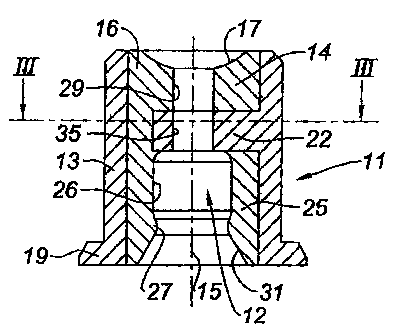
The sealing connector 11 includes an internal sealing component 12 and an
external
slide component 13. The internal sealing component 12 is in this case a double
sleeve
formed in one piece intended to receive two sides of the two male fittings 23,
namely
the outlet fitting 23 of the cartridge and the inlet fitting 32 of the
solenoid valve. The
double sleeve 12 includes a transverse annular partition 14 for dimensional
adjustment
in fact disposed at the bottom of one of the two sleeves of the double sleeve,
the latter
16 being intended to receive the inlet fitting 32 of the solenoid valve. The
partition 14
is designed as a dish 17 on the side of the opening of the sleeve 16 in order
to receive
a spherical hooking portion 18 for the inlet fitting (intermediate fitting)
32.
4
CA 02602723 2010-05-26
The double sleeve 12 with its partition 14 for dimensional adjustment is made
of
flexible material. e.g. a thermoplastic material which can be vulcanised and
injected
and. more generally. an injectable flexible polymer.
The external slide component is a slide 13 in which the double sleeve 12
extends
without play. intended to hold the shape of the flexible double sleeve 12. The
slide 13
has a generally tubular shape with, at one end. an external annular rim 19 for
holding
it in the adapter 1, in cooperation with an internal annular shoulder formed
on the
adapter. The slide 13 includes a transverse annular partition 22 in fact
disposed at the
bottom of the other 25 of the two sleeves of the internal double sleeve 12
intended to
receive the outlet fitting 23 of the cartridge.
In this connection. an internal lip 27 cooperating with the external wall of
the fitting
23 of the cartridge is formed on the internal wall 26 of the sleeve 25 close
to the
opening of the sleeve and its bevelled rim 31 in order to perfect the seal.
The slide 13 with its partition 22 is made of rigid material, e.g. a
polypropylene. This
rigid transverse partition 22 thus serves as a support for one of the
fittings, in this case
the outlet fitting 23 of the cartridge 20. When the fitting 23 of the
cartridge is
engaged in the sleeve 25. there is no risk that it will pierce the flexible
partition 14 as
the rigid partition 22 is inserted between the flexible partition 14 and the
fitting 23.
The rigid transverse partition 22 is provided with orifices 28 for the passage
of the
material of the double sleeve 12, in this case injection-moulded material.
The central bore 29 extending through the flexible transverse partition 14,
the bore 35
which forms a continuation thereof and extends through the rigid transverse
partition
22 and the bore formed by the internal wall 26 of the sleeve 25 which forms a
continuation of' the bore 35 form the duct for the passage of gas of the
sealing
connector 1 1.
In the example of the connector shown in Figures 1-3, not only is the rigid
transverse
partition 22 integral with the slide 13, but the assembly formed by this
partition and
the slide is formed in one piece, in this case by injection moulding. In
addition, it will
be noted that the two transverse partitions, namely the flexible partition 14
and the
gid partition 22. are contiguous.
CA 02602723 2007-09-27
WO 2006/114693 PCT/IB2006/001012
The connection of the inlet fitting 32 of the solenoid valve 30 and the outlet
fitting 2'
of the gas cartridge 20 will now be described.
In order to mount the adapter I on the cartridge 20, the fastening skirt 5 is
inserted
inside the edge 21 of the cartridge 20. The circumferential boss 6 is hooked
and
clipped on to the internal wall of the edge 21.
When the adapter I is fastened to the cartridge 20, the outlet fitting 23 of
the cartridge
20 is guided by the bevelled rim 31 of the sleeve 25 until the edge 33 of the
fitting 2'
comes to bear against the rigid partition 22.
The adapter I is then slid on to the solenoid valve 30 and the connector 11 is
slid on to
the male inlet fitting 32 of the solenoid valve, the fitting engaging in the
sleeve 16 of
the connector 1 1 until the spherical portion 18 of the fitting is housed in
the dish 17 of
the sleeve 16 and therefore the adapter is hooked on to the fitting.
Finally. the connector 11 is mounted on the cartridge 20 and the solenoid
valve 30 by
a relative movement of translation of the three elements.
If, for some reason. it is desired to remove the cartridge 20 from its housing
before it
is empty. by virtue of the slide 13, the connector 11 will be retained in the
adapter I
and the outlet fitting 23 will return to its closing position prior to
mounting.
The first variant embodiment of the connector of Figure 4, shown in very
diagrammatic form, also includes a tubular slide 113 in which a double sleeve
112 is
housed, with its flexible transverse partition 114 for dimensional adjustment.
The
connector I 1 1 of this Figure 4 is distinguished from that of Figures 1-3 in
that the
slide includes two rigid transverse partitions, one 122 serving as a support
for the
outlet fitting of the cartridge and the other 123, adjacent to the flexible
transverse
partition 114. to reinforce it. The two rigid transverse partitions 122, 123
are disposed
at a short distance from one another.
In the second variant embodiment of Figure 5, the connector 211 includes two
sleeves
216 and 225 for receiving the fittings, but not formed in one piece. One.
namely the
connector 216. is made of flexible material in order to receive the inlet
fitting 32 of
the transmission member (solenoid valve) 30. The other, namely the connector
225,
6
CA 02602723 2007-09-27
WO 2006/114693 PCT/IB2006/001012
is made of a rigid material in order to receive the outlet fitting 23 of the
cartridge.
The second rigid sleeve 225 has the particular feature that it is formed in
one piece
with the external slide 213. It extends inside the latter with, in this case,
annular play
250. As for the rest, the flexible annular partition 214 for dimensional
adjustment is
once again situated at the bottom of the first flexible sleeve 216 and the
rigid
transverse annular partition 222 intended to serve as a support for the outlet
fitting 23
of the cartridge is situated at the bottom of the second rigid sleeve 225.
As a result of the rigidity of the sleeve 225, sealing with the outlet fitting
23 of the
cartridge is ensured essentially by an internal lip 227 cooperating with the
external
wall of the fittin`
In the embodiment of Figure 5, the connector is obtained by simple assembly;
with no
need for overmoulding=, as in the case of the connectors of the other figures.
7