Note: Descriptions are shown in the official language in which they were submitted.
CA 02602742 2007-10-10
TITLE OF THE INVENTION
TWO-STEPPED CABINET
BACKGROUND OF THE INVENTION
The present invention relates generally to bathroom cabinets and, more
particularly to a two-stepped bathroom cabinet which provides increased
storage.
In most private residences, including homes and apartments, a cabinet is
typically provided on a wall of each bathroom for the purpose of holding
various
medicines and personal items, such as shaving supplies, first aid supplies,
oral and
other personal hygiene items, and the like. Typically, the door of the cabinet
is
provided with a mirrored outer surface and the cabinet is positioned over or
along side
of a sink. In most installations, the cabinet is intended to occupy what would
otherwise
be dead space within a bathroom wall, and is typically a standard size, with a
width
intended to fit between two upright standardly spaced wall studs.
While such prior art cabinets include shelves generally as deep as the
thickness of the wall, the width of such cabinets is generally limited to the
distance
between two upright wall studs, typically about fourteen inches. While many of
the
personal items need the space provided, smaller items, such as over-the-
counter
medicine bottles and prescription drug containers, tend to be pushed to the
rear and
become hidden behind other items. It is not unusual to "lose" such smaller
items where
they cannot be seen. Although some such cabinets employ doors which are larger
then
the outside dimensions of the cabinet, the doors are hinged to one side of the
cabinet.
Another storage possibility is a cabinet which is flush mounted against
the outer surface of a wall. Such cabinets are typically higher and wider than
cabinets
mounted between the wall studs, but are seldom very deep, as any substantial
depth to
the cabinet is taken from the room space. Such cabinets provide an advantage
in more
conveniently storing and displaying smaller items without them appearing
"lost," but
-1-
CA 02602742 2007-10-10
are limited in the size of the items which can accommodate due to the limited
depth.
Larger (deeper) items must be stored elsewhere.
Others have suggested a combination of both cabinet styles. To date,
however, such combinations have been chiefly for retrofit installations where
a first,
deeper cabinet is intended for use within an existing cabinet space cut into a
wall, and a
second flush mount cabinet is intended to surround the first cabinet.
Typically, the two
cabinets of such combination cabinet design are initially completely
independent of
each other, such that the second cabinet may be positioned independently of
the first
cabinet, often compromising the additional storage space which could be
provided.
Further, as separate units, the manufacture of the two cabinets is expensive,
and
installation is difficult and time consuming, which has added to the overall
cost.
It would be advantageous to provide a modular, two-stepped cabinet
which could provide both shallow and deep storage areas, would be applicable
to both
new and retrofit installations, and would be significantly less expensive and
more
convenient both to manufacture and install.
BRIEF SUMMARY OF THE INVENTION
Briefly stated, the present invention comprises a modular, two-stepped
cabinet providing expanded storage capacity for use in a cabinet space in a
wall. The
cabinet space is defined by a first dimension generally equal to the spacing
between
two adjacent studs in the wall, and a second dimension. The two-stepped
cabinet is
formed of a unitary body comprising a first-step cabinet portion which
includes first
and second lateral sides which are spaced apart by a distance generally
corresponding
to the first dimension, each of the first and second lateral sides of the
first-step cabinet
portion having a forward edge and a rearward edge. The first-step cabinet
portion
further includes upper and lower sides which are spaced apart by a distance
generally
corresponding to the second dimension, each of the upper and lower sides of
the first-
step cabinet portion having a forward edge and a rearward edge. In addition,
the first-
-2-
CA 02602742 2007-10-10
step cabinet portion includes a rear wall joining the reanvard edges of the
first and
second lateral sides and the upper and lower sides of the first-step cabinet
portion. The
unitary body further comprises a second-step cabinet portion. The second-step
cabinet
which includes first and second lateral sides which are spaced apart by a
distance
greater than the first dimension, each of the first and second lateral sides
of the second-
step cabinet portion having a fornvard edge and a rearward edge. The second-
step
cabinet portion further includes upper and lower sides which are spaced apart
by a
distance greater than the second dimension, each of the upper and lower sides
of the
second-step cabinet portion having a forward edge and a reanvard edge. The
second-
step cabinet portion further includes a rear wall joining the rearward edges
of the first
and second lateral sides and the rearward edges of the upper and lower sides
of the
second-step cabinet portion. The rear wall of the second-step cabinet portion
has an
opening extending therethrough, the opening having a width generally
corresponding to
the first dimension, and a height generally corresponding to the second
dimension, the
rear wall of the second-step cabinet portion being integrally formed with the
forward
edges of the first and second lateral sides and the upper and lower sides of
the first-step
cabinet portion. Finally, the forward edges of the first and second lateral
sides and the
forward edges of the upper and lower sides of the second-step cabinet portion
establish
a forward opening to the modular two-stepped cabinet.
A further aspect of the present invention is a convenience cup for
holding articles within a cabinet, the cabinet being provided with an integral
support
permitting attachment of the cup. The convenience cup comprises a body portion
including a generally cylindrical wall, at least a portion of which is
generally flattened,
a closed bottom portion, and an open top portion which combine to define a
hollow
interior portion, generally circular in cross-section, and having a depth
suitable for
holding articles. The convenience cup further comprises an attachment member
for the
demountable attachment of the convenience cup to the integral support of the
cabinet.
BRIEF DESCRIPTION OF THE SEVERAL VIEWS OF THE DRAWINGS
-3-
CA 02602742 2007-10-10
The foregoing summary, as well as the following detailed description of a
preferred embodiment of the invention, will be better understood when read in
conjunction with the appended drawings. For the purpose of illustrating the
invention,
there is shown in the drawings an embodiment which is presently preferred, it
being
understood, however, that the invention is not limited to the specific methods
and
instrumentalities disclosed. In the drawings:
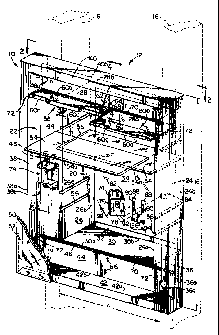
Fig. 1 is a perspective view, partially broken away and partially
exploded, of a two-stepped cabinet in accordance with a preferred embodiment
of the
present invention;
Fig. 2 is a sectional view of a portion of the two-stepped cabinet taken
along line 2-2 of Fig. 1;
Fig. 3 is a sectional view of a portion of the two-stepped cabinet taken
along line 3-3 of Fig. 1;
Fig. 4 is a sectional view of a portion of the two-stepped cabinet taken
along line 4-4 of Fig. 1; and;
Fig. 5 is a sectional view of a portion of the two-stepped cabinet taken
along line 5-5 of Fig. 1.
DETAILED DESCRIPTION OF THE INVENTION
Certain terminology is used in the following description for convenience
only and is not limiting. The words"right," "left," "lower" and "upper"
designate
directions in the drawings to which reference is made. The words "inward,"
"inwardly,"
"outward" and "outwardly" refer to directions toward and away from,
respectively, the
geometric center of the two-stepped cabinet and designated parts thereof. The
terminology includes the words above specifically mentioned, derivatives
thereof and
words of similar import.
Referring to the drawings in detail, wherein like numerals indicate like
elements throughout, there is shown in Fig.1 a perspective view of the unitary
body of
a two-stepped cabinet 10 in accordance with a preferred embodiment of the
present
-4-
CA 02602742 2007-10-10
invention. The two-stepped cabinet 10 is intended to provide expanded storage
capacity, and is intended for use in a cabinet space 12 within a wall, as
illustrated in
phantom. Such a cabinet space 12 is defined by a width or first dimension 14
generally
equal to the spacing between two adjacent studs 16 in the wall, typically
about fourteen
inches in a facility in which the studs 16 are spaced sixteen inches on
center, and a
length or second dimension 18, which is typically in the range of from
eighteen to
twenty-four inches depending upon the particular application. It should be
understood
that the first dimension or width 14 and the second dimension or height 18 of
the
cabinet space 12 and/or the cabinet 10 may vary from the illustrated
dimensions in
particular applications.
The two-stepped cabinet 10 is formed of a generally unitary body
comprising a first-step cabinet portion 20 and a second-step cabinet portion
22. The
first-step cabinet portion 20 includes a first lateral side 24 and a second,
opposite lateral
side 26, the lateral sides 24, 26 being generally parallel to each other and
spaced apart
by a distance generally corresponding to the first dimension 14. The first
lateral side 24
and the second lateral side 26 of the first-step cabinet portion 20 each have
a forward
edge 24a, 26a and a generally parallel rearward edge 24b, 26b.
The first-step cabinet portion 20 further includes an upper side 28 and a
lower side 30, which are also generally parallel to each other and are spaced
apart by a
distance generally corresponding to the second dimension 18. The upper side 28
and
the lower side 30 engage the first and second lateral sides 24, 26. The upper
side 28 and
the lower side 30 of the first-step cabinet portion 20 each have a fonvard
edge 28a, 30a
and a generally parallel rearward edge 28b, 30b.
The first-step cabinet portion 20 further includes a rear wall 32 joining
the rearward edges 24b, 26b of the first lateral side 24 and the second
lateral side 26
and the rearward edges 28b, 30b of the upper side 28 and the lower side 30 of
the first-
step cabinet portion 20 to form a unitary five sided cabinet. Preferably the
depth of the
first and second lateral sides 24 and 26 and the depth of the upper and lower
sides 28
and 30 generally correspond to each other and to the depth of the cabinet
space 12
-5-
CA 02602742 2007-10-10
typically about four inches. In this manner, the first step cabinet portion 20
is sized and
shaped to fit within the cabinet space within the wall such that when the rear
wall 32
abuts a wall at the back of the cabinet space, the fonvard edges 24a, 26a,
28a, 30a of
the lateral sides 24 and 26 and the upper and lower sides 28 and 30 are
generally
aligned with the forward portion of the wall generally surrounding the cabinet
space
and form a first-step cabinet portion opening. Preferably at least a portion
of the rear
wal132 is covered by a mirror 34.
The second-step cabinet portion 22 includes a first lateral side 36 and a
second, opposite lateral side 38, the lateral sides 36, 38 being generally
parallel to each
other and being spaced apart by a distance greater than the first dimension
14. In the
case where the first dimension 18 is about fourteen inches, the spacing
between the first
and second lateral sides 36, 38 of the second-step cabinet portion 22 is
preferably about
twenty inches but could be some other distance, if desired. The first lateral
side 36 and
the second lateral side 38 of the second-step cabinet portion 22 each have a
forward
edge 36a, 38a and a generally parallel rearward edge 36b, 38b.
The second-step cabinet portion 22 further includes an upper side 40 and
a lower side 42, which are generally parallel to each other and are spaced
apart by a
distance greater than the second dimension 18. The upper and lower sides 40,
42 also
engage the first and second lateral sides 36, 38. In the preferred embodiment,
where
the second dimension 18 of the cabinet space is about eighteen inches, the
spacing
between the upper and lower sides 40, 42 of the second-step cabinet portion 22
is about
twenty-six inches. However, the distance and thus the height of the second-
step
cabinet portion 22 may vary depending upon the particular application. The
upper side
40 and the loNver side 42 of the second-step cabinet portion 22 each have a
forward
edge 40a 42a and a generally parallel reanvard edge 40b, 42b. The distance
between
the forward edges 36a, 38a, 40a, 42a and the rearward edges 36b, 38b, 40b, 42b
of the
lateral sides 36, 38 and the upper and lower sides 40, 42 and thus the depth
of the
second-step cabinet portion 22 in the present embodiment is about 2'/~ inches.
-6-
CA 02602742 2007-10-10
However, the depth of the second-step cabinet portion 22 could vary for
particular
applications.
The second-step cabinet portion 22 further includes a rear wall 44
joining the rearward edges 36b, 38b of the first and second lateral sides 36,
38 and the
rearward edges 40b, 42b of the upper and lower sides 40, 42 of the second-step
cabinet
portion 22. The rear wall 44 of the second-step cabinet portion 22 has a
generally
rectangular opening 46 extending therethrough. The opening 46 has a'width
generally
corresponding to the first dimension 14, and a height generally corresponding
to the
second dimension 18 so that the opening 46 corresponds to the opening in the
first-step
cabinet portion 20 established by the forward edges 24a, 26a, 28a, 30a of the
sides 24,
26, 28, 30, of the first-step cabinet portion 20. In addition, the rear wall
44 of the
second-step cabinet portion 22 is integrally formed with the fonvard edges
24a, 26a, of
the first and second lateral sides 24, 26 and the forward edges 28a, 30a of
the upper
and lower sides 28, 30 of the first-step cabinet portion 20. Preferably, the
two-stepped
cabinet 10 is formed of a polymeric material such that the first-step cabinet
portion 20
and the second-step cabinet portion 22 are integrally molded or formed as a
single
unitary structure. As shown in Fig. 2, when the two-stepped cabinet 10 is
installed in a
cabinet space, the first-step cabinet portion 20 is located between the wall
studs 16 and
the second-step cabinet portion engages the wall surface outside of the
cabinet space 12
to provide a finished appearance.
Suitable fasteners, such as wood screws extending into the studs 16 are
employed to secure the two-step cabinet 10 in place. The forward edges 36a,
38b of
the first and second lateral sides 36, 38 and the forward edges 40a, 42a of
the upper
and lower sides 40, 42 of the second-step cabinet portion 22 establish a
generally
rectangular forward opening 48 to the modular two-stepped cabinet 10. The two-
stepped cabinet 10 further includes a door component 50 of a dimension to
close the
forward opening 48. The door component 50 is operatively attached along one
side to
the forward edge 38a of the second lateral side 38 of the second-step cabinet
portion 22
by at least one hinge (not shown) and preferably two or more spaced hinges
(not
-7-
CA 02602742 2007-10-10
shown) in a manner well known in the art. The door component 50 demountably
engages the forward edges 36a, 40a, 42a of the first lateral side 36 and the
upper and
lower sides 40, 42 of the second-step cabinet portion 22 by at least one
closure or catch
(not shown). The closure or catch may be a magnetic or mechanical catch of the
type
well known to those skilled in the art or may be omitted, if desired.
Preferably, the
door component 50 includes a mirrored surface 52 as at least the outer or
exposed
surface and may include a mirrored surface (not shown) as the interior
surface.
The first-step cabinet portion 20 includes at least one repositionable
shelf 54. Each of the first and second lateral sides 24, 26 of the first-step
cabinet
portion 20 includes a plurality of integral shelf supports in the form of
generally
aligned slot pairs 56 with each of the slots of each slot pair 56 having a
thickness the
same as or slightly thicker than the thickness of the shelf 54. The length of
the shelf 54
is slightly less than the total distance from side to side between the base
portion of the
slots of each slot pair 56. In this manner, the shelf 54 is slidably received
and fully
supported within any one of the slot pairs 56. Preferably, the depth of the
shelf 54
extends beyond the depth of the first-step cabinet portion 20 and preferably
generally
corresponds to the combined depth of the first and second-step cabinet
portions 20, 22
so that when the shelf 54 is installed within one of the slot pairs 56 as
illustrated, the =
front edge 54a of the shelf 54 is generally aligned with the front edges 36a,
38a of the
lateral sides 36, 38 of the second-step cabinet portion 22. In this manner,
large items
such as rolls of toilet paper, large bottles, and the like may be stored
within the cabinet
10. In the embodiment illustrated, four different slot pairs 56 at differing
heights are
provided for two shelves 54. However, it will be appreciated by those of
ordinary skill
in the art that a single shelf 54 or three or more shelves may be employed and
that a
greater or lesser number of slot pairs 56 may be employed. Further, in the
illustrated
embodiment, the shelf 54 is made of a generally transparent material, such as
glass.
However, the shelf 54 may alternatively be made of any other transparent or
non-
transparent generally rigid, lightweight material, such as a polymeric
material or a
metallic material, if desired.
-8-
CA 02602742 2007-10-10
The second-step cabinet portion 22 also includes at least one removable
shelf assembly 58. In the presently preferred embodiment, the shelf assembly
58
includes a pair of removable shelf members 60 and a separate, removable shelf
support
member 62. As best shown in Figs. 1, 3 and 4, the shelf members 60, which
preferably
are made of a polymeric material, are generally flat and rectangularly shaped,
having a
length generally corresponding to about one-half of the overall width of the
second-step
cabinet portion 22 and having a width generally corresponding to the depth of
the
second-step cabinet portion 22. The outermost edge 60a of each of the shelf
members
60 includes a generally upwardly extending ledge or lip 60c to help prevent
small
articles from rQlling or falling off of the shelf members 60.
As best shown in Figs. 1 and 4, the shelf support member 62, which also
is preferably made of a polymeric material, is generally triangularly shaped.
The rear
edge 62b of the shelf support member 62 includes a pair of lugs 64 with each
lug
extending outwardly in an opposite direction from the other lug. The rear wall
32 of
the second-step cabinet portion 22 includes a pair of generally rectangularly
shaped
keepers 66 which are sized and spaced to receive the lugs 64 of the shelf
support
member 62 for supporting the shelf support member 62 in the position as shown
in Fig.
1. The lower end of the shelf support member 62 includes a pair of slots 68 on
opposite sides thereoE Similar slots 70, 72 are located on the rear wall 44
and the
lateral sides 36, 38 respectively of the second-step cabinet portion 22. When
the shelf
support member 62 is installed as shown in Figs. 1, 3 and 4, the slots 68 on
the shelf
support member 62 align with the slots 70, 72 on the rear wall 44 and first
and second
lateral sides 36, 38 of the second-step cabinet portion 22 for receiving and
retaining the
rear edge 60b and the side edges of the shelf members 60 to thereby retain the
shelf
members 60 in place as shown. Preferably, the slots 70, 72 are preformed when
the
two-step cabinet 10 is fabricated. Of course, when the two-step cabinet 10 is
installed
as shown in Fig. 1, the lower side 42 of the second-step cabinet portion 22,
as well as
the lower side 30 of the first step cabinet portion 20 serve as additional
shelves for
supporting items within the two-cabinet 10.
-9-
CA 02602742 2007-10-10
The two-step cabinet 10 further includes at least one and preferably two
convenience cups 74 which may be employed for storing elongated items such as
a
toothbrush, hairbrush or the like. Each convenience cup 74 includes a body
portion
comprising a generally cylindrical wall 76, at least a portion of which 78 is
generally
flattened, and a closed bottom portion 80. Preferably, the top of the
convenience cup is
open, thereby defining a generally hollow interior portion having a depth
suitable for
holding articles. As best shown in Figs. 1 and 5, an attachment member, in the
present
embodiment, a generally inverted L-shaped clip 82 extends outwardly from the
flat
portion 78 of the convenience cup 74. The attachment member or clip 82 is
adapted for
insertion into an integral support such as a generally rectangularly shaped
keeper 84
extending from the rear wa1144 of the second-step cabinet portion 22 for
locating and
retaining the convenience cup 74 in place as illustrated. Preferably, the
convenience
cup 74 is also made of a polymeric material.
The two-step cabinet 10 further includes a spacing member 86 which
may be employed to facilitate holding the convenience cup 74 firmly in place.
The
spacing member 86 which is generally flat and includes t~vo leg members 88 is
also
preferably made of a polymeric material. Each of the leg members 88 includes a
generally rectangularly shaped opening 90 which is adapted to receive therein
a pair of
elongated strips 92 extending outwardly from the rear flat portion 78 of the
convenience cup 74. In this manner, the strips 92 extend into the openings 90
to help
support the spacing member 86 when the convenience cup 74 is installed with
the L-
shaped clip 82 extending into the keeper 84 of the rear wall 44 of the second-
step
cabinet portion 22. As best shown in Fig. 5, the spacing member 86 extends
below the
bottom 80 of the convenience cup 74 and includes a pair of generally outwardly
extending spaced apart post members or lugs 94. The distal ends of each of the
lugs
94 extend slightly upwardly as shown in Fig. 5. The lugs 94 may be employed
for
holding elongated articles such as disposable shavers as illustrated.
Preferably, the
convenience cup 74 and the spacing member 86 are positioned as shown in Fig. 1
-10-
CA 02602742 2007-10-10
approximately midway between the upper side 40 and the lower side 42 of the
second-
step cabinet portion 22.
As illustrated in Fig. 1, the two-step cabinet 10, when installed in the
cabinet space 12 as shown, has a door component 50 with hinges (not shown)
along the
left side (second lateral side 38 often second-step portion 22) so that the
door 50 swings
open or pivots from the left side of the cabinet 10. In some situations, it
may be
desirable to have the cabinet 10 open from the right side (not shown). In such
situations, the cabinet 10 may be merely turned upside down (i.e., rotated 180
degrees)
and installed with the door hinges toward the right side. In the case of such
an
installation, the shelf assembly 58 would be installed in the same manner
utilizing the
slots 70 and 72 and the keepers 66 which are located near the bottom of the
two-step
cabinet 10, i.e., near the lower side 42 of the second-step cabinet portion 22
in the
present orientation. The convenience cups 74 and the spacing members 86 would
likewise be installed in the opposite orientation.
From the foregoing description, it can be seen that the present invention
comprises a unitary two-stepped cabinet which is adapted for installation
within an
opening in a wall and which provides enhanced cabinet storage. It will be
recognized
by those skilled in the art that changes may be made to the above-described
embodiment of the invention without departing from the broad inventive
concepts
thereof. It is understood, therefore, that the invention is not limited to the
particular
embodiment and arrangement disclosed, but is intended to cover all
modifications
which are within the scope and spirit of the invention as defined by the
appended
claims.
-11-