Note: Descriptions are shown in the official language in which they were submitted.
CA 02602839 2007-09-28
WO 2006/130062 1
PCT/SE2006/000416
SCREENING ARRANGEMENT
Background of the invention
The present invention relates to a screening
arrangement in a vibrating screen for screening of
material, such as crushed stone, gravel or the like, the
screening arrangement being a cross-tensioned or a
longitudinally tensioned screening media.
In mining and stone industries, it is in many cases
important to fractionate crushed stone and gravel into
fractions of stones with different sizes. Normally, a
deviation from the size is permitted according to industry
standards, e.g. 10 percent oversized particles and 15
percent undersized particles.
In most cases, fractionating is done by supplying an
unfractionated stream of crushed stone or gravel to a
vibrating screen provided with a screening deck including
screening holes for allowing stones smaller than the
screening holes to pass through the holes. The vibration
pattern and the inclination of the vibrating screen are
arranged so that the crushed stones continuously flow in
one direction on the screen, ultimately leaving it on one
side or falling through the holes in the screening deck.
To improve the screening of the unfractionated
material and to get a thicker material layer on the
screening deck some screening devices are provided with
raised portions, see e.g. SE-C2-524 179 and EP-B1-0 680
386. In SE-C2-524 179 stiffening longitudinal beams are
arranged on top of the screening deck to reduce the wear on
the screening holes and to make undersized particles to
pass faster through the screening deck. In EP-B1-0 680 386
a curved surface in the form of longitudinal ridges has
been arranged on top of the screening deck, where the
curved surface is a fine screening screen. The curved
CA 02602839 2013-03-20
WO 2006/130062 2
PCT/SE2006/000416
surface aims to provide a larger screening surface and to
prevent material from being screened to migrate toward the
lower sides of the screen.
Another application of a non-flat screening deck is
disclosed in US-B-6 607 080 and US-B16 629 610, where
systems for separating particles from a mix of particles
and fluids by a screen with shale shakers used in the
drilling industry are shown. The screen is designed with a
flat screening deck and with ramps so that a portion of the
fluids will pass over the ramp, whereas the screen will
separate the particles from the remaining portion
containing both particles and fluid.
The problem with the above prior art solutions and
screening devices having only a flat screening deck is that
none of them reduces the traveling speed of the material to
be stratified as it passes over the screening deck.
Furthermore they do not include means for stirring or
mixing the material to improve the screening.
Faced with the above prior art screening systems and
the disadvantages and problems therewith, the object with
the present invention is to provide a solution to how to
improve screening efficiency in a simple way with a
screening assembly for a vibrating screen for screening of
unfractionated material such as crushed stone and gravel.
Summary of the invention
The above-mentioned objects are achieved by an
arrangement, which comprises means arranged on top of the
screening media for stirring the screened material, the
stirring means being raised portions on the surface of the
screening media, where the raised portions are arranged
transversely to the travel direction of the screened
material.
CA 02602839 2007-09-28
WO 2006/130062 3
PCT/SE2006/000416
Brief description of the drawings
In the following, the invention will be explained
with reference to the accompanying drawings, wherein
Fig. 1 is a schematic perspective assembly view of a
screening media according to the invention,
Fig. 2 is a front view of the screening media
according to the invention,
Fig. 3 is a top view of the screening media according
to the invention,
Fig. 4 is a side view of the screening media
according to the invention showing shortening positions,
Fig. 5 is a side view of the screening media
according to the invention,
Figs. 6-7 show enlarged details C and D of the
screening media of Fig. 5,
Fig. 8 is a side view of the screening media
according to the invention,
Figs. 9-12 show the enlarged details E, F and G of
the screening media of Fig. 8,
Fig. 13 is a perspective view of the screening media
according to the invention as it is mounted in a screen,
and
Fig. 14 is partial view of the arrangement of Fig.
13.
Description of preferred embodiments
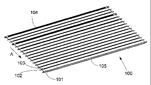
Fig. 1 schematically shows a screening media 100 for
a vibrating screen for screening of crushed stones, gravel
or the like. The screening media 100 is a cross-tensioned
screening media that is arranged in a vibrating screen by
means fastening arrangements 170 in each end of the
screening media that fasten the screening media 100 to the
walls 200 of the vibrating screen. The screening media 100
comprises a screening surface 101, wires 102 and raised
portions 103.
CA 02602839 2007-09-28
WO 2006/130062 4
PCT/SE2006/000416
The screening media 100 is further provided with a
beginning portion 104 and an end portion 105. The beginning
portion 104 defines the portion of the screening media 100,
where the material to be screened enters the screening
media 100. The end portion 105 defines the portion of the
screening media 100, where the material leaves the
screening media 100. A longitudinal direction of the
screening media 100 is indicated with an arrow A in Fig. 1.
The longitudinal direction of the screening media is also
the traveling direction for the material, i.e. stones or
gravel, on the vibrating screen.
Fig. 2 shows a front view of the screening media 100
having projecting wires 102 at each longitudinal side of
the screening media 100. Fig. 3 shows a top view of the
screening media 100. In both Figs. 2 and 3 only a few of
the wires 102 and the raised portions 103 are indicated,
but it is obvious for a man skilled in the art that wires
102 and raised portions 103 are arranged at intervals from
the beginning portion 104 and the end portion 105.
Fig. 4 shows a side view of the screening media 100
in its entire length. The screening media 100 comprises a
screening surface 101, wires 102 and raised portions 103.
The screening surface 101 is provided with through holes
(not shown) for fractionating crushed stone and gravel into
fractions of stones with different sizes.
The wires 102 and raised portions 103 are arranged
perpendicular to the longitudinal direction of the
screening media 100 and at a distance between each other
along the entire length of the screening media 100. Between
each raised portion 103 the screening surface 101 is
arranged. At every raised portion 103 at least one wire 102
is arranged. The wires 102 are connected to the attaching
means to fasten the screening media 100 to the walls of the
vibrating screen.
CA 02602839 2007-09-28
WO 2006/130062 5
PCT/SE2006/000416
To make the length of the screening media 100
flexible, the screening media 100 is provided with certain
shortening positions 106-109, see Fig. 4, i.e. positions
where the screening media 100 is prepared to be cut off. At
the positions 106-109 several raised portions 103 can be
arranged, where at least one of the raised portions 103 at
the positions 106-109 is provided with two wires 102. If
the screening media is shortened, the portion of the
screening media left of the shortening positions 106-109
and the raised portion 103, having two wires 102
incorporated (as shown in Figs. 7, 9 and 10), are cut off.
Thus, the modified and shortened screening media has a new
beginning portion defined by the raised portion 103 having
two wires 102 incorporated at the cut-off position 106-109.
The raised portions 103 may have slightly different
shapes as shown in Figs. 7 and 9-12, but all shapes have
some common features, i.e. having a slightly increasing
slope along the longitudinal direction of the screening
media 100 to a top portion of the raised portion 103 and
having a steep slope or almost a vertical end portion. The
length, height, start portion and end portion of the raised
portion 103 affect the stirring effect of the raised
portion 103 and are selected to achieve the most effective
stirring of the material to be screened. The shape of the
raised portions 103 is also affected by the thickness of
the screening surface. This is shown in Fig. 6, where the
raised portion 103 is arranged on a plateau.
The raised portions 103 can also be arranged so that
not every raised portion 103 has the same shape to create
different stirring effects along the screening media. For
example every second raised portion 103 may have the same
shape, e.g. a higher shape, and those therein between may
have another shape, e.g. a lower shape. The raised portions
could also be arranged so that the raised portions 103,
having two wires 102 incorporated are longer and lower,
CA 02602839 2007-09-28
WO 2006/130062 6
PCT/SE2006/000416
whereas the raised portions 103, having one wire 102
incorporated, are shorter and higher. In the shown
embodiments, the raised portions 103, having two wires 102
incorporated are longer (see Fig. 7), whereas the raised
portions 103, having one wire 102 incorporated, are shorter
(see Fig. 7).
Fig. 6 shows an enlargement C of Fig. 5 of the end
portion 105. Fig. 7 shows an enlargement D of Fig. 5 of the
beginning portion 104. Fig. 9 shows an enlargement E of
Fig. 8 of the screening media 100 including the shortening
positions 107-108. Figs. 10-11 show an enlargement F of
Fig. 8 of the screening media 100 including the shortening
position 109. Fig. 12 shows an enlargement G of Fig. 8 of a
raised portion 103.
The screening media 100 comprises different
materials. Both the screening surface 101 and the raised
portions 103 are typically made of polymeric materials,
e.g. polyurethane (PU) or rubber. Both the screening
surface 101 and the raised portions 103 can be made of the
same material, but in a preferred embodiment, the raised
portions 103 are manufactured of relatively unresilient PU,
whereas the screening surface 101 is manufactured of a more
resilient PU. The preferred materials for the raised
portions 103 have a hardness that preferably is in the
range from about 50 Shore A to about 95 Shore A, and the
preferred materials for the screening surface 101 have a
hardness of about 30 Shore A to about 95 Shore A.
Preferred materials are e.g. PU, rubber, PVC,
polyethylene, polyamide, polyester, urethane rubber,
suitable natural rubber compounds, other rubber materials
or the like for both the raised portions 103 and the
screening surface 101. The wires 102 are typically made of
steel, Kevlar, Twaron, polyester or aramid fibers. The term
"wire" has been used throughout the description and the
appended claims with meaning of an arrangement having
CA 02602839 2007-09-28
WO 2006/130062 7
PCT/SE2006/000416
reinforcing and tensioning functionality and the "wires"
are made of any of the above-disclosed materials.
The screening media can also be provided with wires
at every second position of the raised portions, but not at
the shortening positions. It also possible to have a
screening media, where the raised portions are arranged at
every second wire position.
The screening media can also be longitudinally
tensioned, either by only rotating the screening media
shown in e.g. Fig. 1 or by arranging the wires parallel
with the longitudinal direction A of the screening media
and arranging the spaced raised portions perpendicular to
the longitudinal direction A.
In Fig. 13 is shown screening media 100 that is
mounted in a vibrating screen. The screening media 100 is
attached to the sidewalls 200 of the vibrating screening by
a hook arrangement 160, 170. Hooks 170 is arranged at the
ends of the of the screening media 100, see Fig. 14, and
corresponding and interacting hooks 160 are arranged on the
sidewalls 200. The hooks 160 are provided with bolt and
nuts arrangement 180 to tension the screening media 100
between the sidewalls 200 of the screen. The screen is
further provided with support beams or barriers 190 between
the sidewalls 200 of the vibrating screen having their
longitudinal direction parallel to the sidewalls 200 of the
vibrating screen. The support beams or barriers 190 are
arranged at different heights in order to support the
cross-tensioned screening media 100 between the sidewalls
of the vibrating screen, forming the cross-tensioned
screening media 100 to have a crowned or slightly upwardly
curved shape and to support the cross-tensioned when being
mounted.
In Fig. 13 a holding-down arrangement 150 is shown,
which is used if the vibrating screens are very wide. The
holding-down arrangement 150 is arranged with down holding
= CA 02602839 2013-03-20
WO 2006/130062 8 PCT/SE2006/000416
means, e.g. longitudinal beam fixed by bolts or the like,
for holding down the middle of the cross-tensioned
screening media 100 so that the crowned shape is not too
high, which either vise could cause the material to be
screened to deviate to the sides giving a bad screening as
result. Thereby two crowned shapes are arranged with the
cross-tensioned screening media 100 over the width of the
vibrating screen. In a narrower screen the holding-down
arrangement 150 is naturally omitted, since it is not
needed.
The invention should not be limited to the embodiments
disclosed or illustrated, and modifications are possible
within the scope of the appended claims as purposively
construed.
20