Note: Descriptions are shown in the official language in which they were submitted.
CA 02602908 2007-09-20
WO 2006/102609 PCT/US2006/010873
ELECTRIC MACHINE AND METHOD OF MANUFACTURE
CROSS REFERENCE TO RELATED APPLICATIONS
This application claims the benefit of priority of U.S. Provisional
Application
No. 60/664,445, filed 23 March 2005, which is hereby incorporated by reference
in its
entirety.
FIELD OF THE INVENTION
This invention relates to electric machines, such as electric motors, electric
generators, and machines that can function as both. It also teaches methods of
manufacturing machines and assembling them.
BACKGROUND OF THE INVENTION
There are various types of conventional electric machines including motors and
generators and machines that function as both motors and generators. These
conventional electric machines are designed and controlled (operated) using
various well
known engineering and control principles. Conventional electric motors include
those
powered by alternating current (AC) and direct current (DC). Some exemplary
prior art
electric machines include AC induction motors, reluctance motors, DC brushed
motors,
and brushless AC synchronized permanent magnet motors. In general, with
appropriate
machine controls a conventional electric machine can operate as both an
electric motor
and generator.
Conventional electric machines typically comprise a moveable portion, often
referred to as a rotor, and a stationary portion, often referred to as a
stator. A
conventional rotor can be formed using techniques well known in the art. Two
conventional rotor designs include a conductive wire cage rotor, such as for
example, a
rotor for an AC induction motor and a plurality of permanent magnets formed
into a
rotor, such as for example, a rotor for a brushless AC synchronized permanent
magnet
motor. A conventional stator comprises a plurality of elements which are often
referred
to as poles. A conventional stator can be formed using techniques well lcnown
in the art.
The end of the stator pole is often referred to as the pole face. The faces of
adjoining
pole are separated from each other by an air gap. An electrically conductive
material
shaped as a wire, often referred to as winding, is wound around each pole. The
winding
I
CA 02602908 2007-09-20
WO 2006/102609 PCT/US2006/010873
has an exterior electrical insulation material that forces the electric
current to move
through the winding rather that short circuiting through the winding.
A conventional electric machine is operated by a machine controller.
Conventional controllers are designed and operated using engineering and
control
principles well known in the art. Conventionally the machine winding is
electrically
connected to the controller using well Icnown designs and techniques. The
controller is
also electrically connected to a power supply and a user input. The controller
allows the
winding to be selectively energized with an electric current from the power
supply. The
electric current travels from the power supply to the winding in a controlled
direction
and amount. As the electric current moves around the winding of the stator
pole, an
electro-magnetic field is generated in accordance with well known engineering
principles. A temporary electro-magnetic field is generated at the stator pole
face. The
strength of the magnetic field depends on the stator material, the amount and
quality of
the winding and the amount of electric current. If the direction of electric
current flow to
the winding is reversed, the pole direction of the magnetic field will reverse
as well, such
as for example, from North to South. If the electric current is removed from
the winding,
the electro-magnetic field ends. The stator pole magnetic fields are thus
temporary and
are often referred to as electromagnets or soft magnets.
Improved controls, electronic hardware, digital signal processors (computers),
and software have allowed electric machines to operate more efficiently, for
example by
the use of electronically controlled pulsed energization of the windings.
These
conventional techniques allow flexible control and efficient operation of the
machine.
Typical control techniques include controlling the amount of electric current
from the
power supply. In addition, some conventional controls manipulating one or more
of the
following electric current features: current direction, shape, amplitude,
pulse width, duty
cycle, etc. By utilizing such advance current control techniques on the
machine its
perforinance and efficiency can be improved. However, there is a need not met
in the
prior art for an electric machine with improved structural configurations,
designs,
manufacturing and assembly methods.
BRIEF SUMMARY OF THE INVENTION
The invention described in this application overcomes the above described
deficiencies of the prior art by teaching an improved machine design, machine
2
CA 02602908 2007-09-20
WO 2006/102609 PCT/US2006/010873
configurations and method of assembly or manufacture. Advantages of the
invention are
achieved, at least in part, by development of a hub to retain the machine to a
frame, for
example the stator to a bicycle. In one invention embodiment of the machine
that
comprises a rotor and a stator that are separated by an air gap. The rotor
exemplary
comprises a plurality of magnet poles, referred to as perinanent or hard
magnets. The
magnets are aiTanged in alternating magnetic polarity at the air gap opposite
the stator
poles. The stator comprises a plurality of poles wrapped with a conductive
winding,
referred to as electromagnets or soft magnets. A controller is electrically
connected to
the winding. The controller controls electrical current flow to the stator
windings. The
rotor and stator interact with each other by electromagnetic forces. The
rotor, stator, and
controller are located in the same housing with a central aperture. The
controller is
electrically connected to a power supply. The hub is secured to the stator and
is at least
partially located inside the housing.
Additional advantages of the invention described herein are readily apparent
to
one skilled in the art from the following detailed description of the
invention and figures.
Only exemplary embodiments of the invention are shown and described which
illustrate
the best mode contemplated by the inventor for practicing the invention. As
one skill in
the art will appreciate, the invention is capable of one or more additional
embodiments.
In addition one or more of the elements described herein are capable of
modifications
while still being within the scope of the invention. The description and
figures are to be
regarded as illustrative of the best mode and not as unnecessarily restricting
the scope of
the invention.
BRIEF DESCRIPTION OF THE FIGURES
Exemplary embodiments of the invention are illustrated in the accompanying
figures. The illustrations are exemplary and are provided to teach the
invention. Unless
specifically pointed out, no limitations are intended as to the scope of the
invention by
the illustrated embodiments. Reference numbers have been added to the figures
to point
out the various elements of the invention and to aid the reader with
understanding the
invention.
Figure 1 is a perspective view of an exemplary machine embodiment in
accordance with the invention.
Figure 2 is an exploded perspective view of Figure 1.
3
CA 02602908 2007-09-20
WO 2006/102609 PCT/US2006/010873
Figure 3 is a perspective view of an exemplary housing.
Figure 4 is an opposite perspective view of Figure 3.
Figure 5 is a perspective view of an exemplary magnet.
Figure 6 is a perspective view of an exemplary back iron:
Figure 7 is a perspective view of an exemplary magnet retention device.
Figure 8 is a perspective view of a spacer.
Figure 9 is a side elevation view of Figure 8.
Figure 10 is a perspective view of an exemplary housing cover.
Figure 11 is a side elevation view of Figure 10.
Figure 12 is an exemplary stator lamination formed in accordance with the
invention.
Figure 13 is an exemplary stator formed in accordance with the invention.
Figure 14 is a side elevation view of Figure 13.
Figure 15 is a perspective view of an exemplary stator bobbin.
Figure 16 is an opposite perspective view of Figure 15.
Figure 17 is an exemplary stator pole wound in accordance with the invention.
Figure 18 is a perspective view of an exemplary stator hub in accordance with
the
invention.
Figure 19 is an opposite perspective view of Figure 18.
Figure 20 is a cross sectional view of Figure 19 taken at line 20-20.
Figure 21 is a perspective view of the stator secured to the hub with a
machine
controller secured to the hub in accordance with the invention.
Figure 22 is a perspective view of the opposite side of the machine controller
of
Figure 21.
Figure 23 is a perspective view of an exemplary position sensor guard in
accordance with the invention.
Figure 24 is a perspective view of an exemplary electronic assembly reteiition
device in accordance with the invention.
Figure 25 is a perspective view of an exemplary magnet indicator ring in
accordance with the invention.
Figure 26 is a perspective view of an exemplary machine mounting device in
accordance with the invention.
4
CA 02602908 2007-09-20
WO 2006/102609 PCT/US2006/010873
Figure 27 is a plan view of an exemplary use of the machine in accordance with
the invention.
Figure 28 is a plan view of another exemplary use of the machine in accordance
with the invention.
Figure 29 is a perspective view of an exemplary device for securing the
machine
to a wheel in accordance with the invention.
Figure 30 is a perspective view of an exemplary removable part for the device
of
Figure 29.
Figure 31 is a perspective view of an exemplary cover for the side opening of
the
device of Figure 29 in accordance with the iiivention.
Figure 32 is a side elevation view of the cover of Figure 31.
Figure 33 is a block design of an exemplary control arrangement for the
machine
in accordance with the invention.
Figure 34 is a perspective view of an exemplary electrical connection.
DETAILED DESCRIPTION OF THE INVENTION
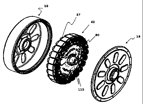
Figure 1 is a perspective view of an electric machine 100 according to the
invention described in this application. Figure 2 is an exploded view of
Figure 1. The
electric machine 100 exemplary comprises three descriptive parts: a rotor 10
(which
may be forined from several elements include the machine housing) a stator 60,
machine
controller 80, hub 110, and cover 18. It is to be understood that each of the
descriptive
parts can comprise more than one part or element. An exemplary hub 110 is
illustrated
secured to the stator 60. The individual elements used to form the machine 100
are
illustrated in more detail in Figures 3-26. For simplicity of explanation,
elements that
are not necessary for understanding the invention, such as screws, fastener,
repetitive
items, and the like have not been illustrated.
The rotor 10 is the machine's 100 rotating part. The term "rotor" used herein
generally refers to all the machine elements that rotate, including the
optional housing as
described below. The stator 60 is the machine's stationary part and does not
rotate
relative to the rotor 10. The term "stator" used herein generally refers to
all the machine
elements that are stationary relative to the rotor. The machine 100 is
exemplary secured
to a frame, such as an electric vehicle (see Figures 27-28) or a stationary
device, such as
a laundry machine (not shown) or other industrial machine (not shown).
5
CA 02602908 2007-09-20
WO 2006/102609 PCT/US2006/010873
The term electric machine 100 as used herein throughout the specification and
claims to describe the invention is not to be viewed as limiting the scope of
the invention
in anyway, unless explicitly stated. The term "machine" refers to any type of
mechanical
device that can operate as a motor, a generator, or both using motor control
techniques
well known in the art. As a motor, the machine 100 converts electrical energy
into
mechanical energy, for example, transferring electric current from a battery
to the
machine controller to the stator to rotate the rotor 10 by electro-magnetic
forces. As a
generator, the machine 100 converts mechanical energy into electrical energy
by electro-
magnetic forces, for example, generating electric current in the stator from
the rotating
rotor through the machine controller to recharge a battery that is
electrically connected to
the machine. Ideally, the machine 100 can be a motor under certain
circumstance and a
generator under otliers, using well known machine control 80 and engineering
techniques.
In a first exemplary embodiment of use the machine 100 operates as a motor
using techniques well known in the art. The machine rotor 10 is secured to a
whee1240
(Figures 27-28). The wheel is secured to a vehicle 200, 300 or vehicle frame.
The
machine 100 converts electrical energy from a battery into mechanical energy
to rotate
the rotor 10. The rotor 10 transfers rotational mechanical energy to the wheel
thus
propelling the vehicle using technique's well known in the art.
In a second exemplary embodiment of use the same machine 100 operates as a
generator using techniques well known in the art. The machine rotor 10 is
secured to a
wheel which is secured to a vehicle or vehicle frame. The machine 100 converts
rotational energy from the wheel into electrical energy. In one exemplary
method the
operator signals the machine controller 80 to generate electricity by creating
a signal
such as operating or manipulating a mechanical friction bralce. When the
operator
applies the friction brake, the machine controller 80 adjusts the machine's
operation to
electromagnetically resist the rotating wheel thus generating electrical
current using
techniques well known in the art. The electrical current is typically supplied
to a battery
or other suitable device. This type of electricity generation from
electromagnetic forces
is commonly referred to as "regen" or "regeneration." In another exemplary
method,
regeneration can occur when the operator of an electric bike or scooter
disengages the
machine throttle. The back electromagnetic force ("EMF") created by the
6
CA 02602908 2007-09-20
WO 2006/102609 PCT/US2006/010873
electromagnetic interaction between the rotating rotor 10 and stationary
stator 60 can be
converted into electrical energy by the machine controller 80 using techniques
well
known in the art.
An exemplary machine 100 can be secured to any suitable power supply (not
shown), such as one or more batteries or a fixed electrical outlet, such as a
common
industrial or residential electric outlet. In a typical vehicle application
the power supply
is a plurality of batteries, such as, for example, batteries made from one or
more of the
following chemistries: lithium ion, lithium polymer, nickel metal hydride, or
lead acid
batter. In other applications, the power source can be a combination of
batteries and one
or more electrical generators. When the electrical generator is powered by an
internal
combustion engine, it is typically referred to as a "hybrid" configuration as
the machine
power supply can be either from a battery or a generator. Regardless of the
power
source, it is to be understood that it may be possible to transform the
mechanical/electrical energy into the proper form, such as from direct current
to
alternating current or vice versa, using techniques well known in the art.
In the following description, the term "rotor" refers to several elements that
are
secured or supported by each other and rotate during machine operation
including the
housing 20, cover 18, back iron 30, magnets 37, and rotor spacer 50. Figures 3
and 4
illustrate an exemplary machine housing 20. The housing 20 is illustrate with
an
exemplary partially closed side 14 with a central aperture 16. An exemplary
rim 23 is
illustrated secured to the housing 20 surrounding the central aperture 16. It
is to be
understood that the rim 23 could also include one or more well known bearing
configurations. A plurality of exemplary cover retention elements 22 are
illustrated at
the perimeter of the housing 20. The retention elements retain the rotor
spacer 50 and
housing cover 18 to enclose the open side of the housing at the exposed end of
perimeter
12. A plurality of exemplary machine mounting features 24 (shown as apertures)
are
illustrated at the outward perimeter of the partially closed side 14 of the
housing 20. A
plurality of exemplary strength elements 26 are illustrated along the closed
surface of the
housing 20. These elements 26 increase the strength of the housing 20 and also
may aid
with heat removal during machine operation. In an exemplary embodiment, the
strength
elements 26 project outward from the surface of the housing 20 to increase
contact with
surrounding air.
7
CA 02602908 2007-09-20
WO 2006/102609 PCT/US2006/010873
It is to be understood that any suitable retention element 22, mounting
features
24, or strength element 26 may be formed on the housing 20 using techniques
well
known in the art. In an exemplary embodiment, the housing is formed from a
lightweight but strong metal, such as Aluminum, but any suitable material may
be used.
In an exemplary method of manufacture, the housing 20 is formed from a die
stamping
or casting process using techniques well known in the art. In another
exemplary method,
the rim 23 is cast or stamped as a separate piece and secured to surface 14
using
techniques well lcnown in the art. In another exemplary method a rotating
bearing device is secured to the rim 23.
Figure 5 illustrates an exemplary magnet 37, often referred to as pernlanent
magnets. Exemplary magnets include NdFeB magnets or other suitable magnet
material.
The magnets have a first 38 and second 39 side. The magnets 37 having a magnet
polarity that runs in a radial direction from one side to the other 38, 39.
Figure 6
illustrates an exemplary back iron stack 30, often referred to as back iron.
The magnets
37 are secured to the back iron 30 along inside perimeter 34 in alternating
magnetic
polarity of north or south using techniques well known in the art. The back
iron 30
concentrates or strengths the magnet's 37 magnetic field. In an exemplary
method the
magnets 37 are located along the inside of the stack 30 with physical
separation between
the individual magnets 37. The stack 30 exemplary comprises an alignment and
separation guide 36 for ease of placement of the magnets 37. In addition, one
or more
exemplary retention aids or structural features 32 are illustrated along the
outside
perimeter of the stack 30. In general, the rotor can comprise simply the
magnets 37 and
back iron 30. The rotor 10 is further dimensioned so that the magnets 37 are
separated
from the stator 60 by an air gap. Maintaining a tight air gap tolerance is
critical to
optimal machine operation. There are twenty (20) magnet poles illustrated. In
an
exemplary embodiment, the number (n) of magnet poles are equal to n times 10
magnet
poles, where n is any whole number greater than 0(n>0), for example, 10, 20,
30, 40
magnet poles, etc.
Figure 7 illustrates an exemplary magnet retainer 40 with a central aperture
41.
The retainer 40 is placed on the inside perimeter of the magnets 37 and
retains them
against the back iron 30. An exemplary retention element 42 or rim or lip is
illustrated to
align with the housing 20 and back iron 30. It is to be understood that the
back iron 30,
8
CA 02602908 2007-09-20
WO 2006/102609 PCT/US2006/010873
magnets 37, retainer 40 can have numerous geometries, magnetic field
properties and can
be changed for engineering, ease of manufacture, cost of manufacture or
machine
perfonnance using techniques well known in the art.
Figures 8 and 9 illustrates an exemplary motor housing spacer 50. The spacer
50
can be made of any suitable material, such as, for example, aluminum or
plastic. It can
be fabricated by die casting methods, in an exemplary unitary piece or in more
than one
piece using techniques well known in the art. An exemplary guide pin 56 is
shown.
Also shown are exemplary indentations 54 and partial apertures 52. The spacer
50
allows the machine cover 18 to be exemplary secured to the motor housing 20
without
damaging the rotor 10 pr stator 60. It is to be understood that the spacer 50
could be
configured into numerous embodiments and may not even be required for some
electric
machine embodiments depending on rotor and housing design. It is also to be
understood that a housing spacer 50 could be located on only side of the
housing 20.
One skilled in the art will appreciate that the spacer 50 should ideally move
only in
relation to the motor housing 20.
Figures 10 and 11 illustrate an exemplary cover 18 for the housing 20. The
cover
18 has a central aperture 17 that is aligned with the central aperture 16 of
the housing. It
also has a plurality of retention elements 19, strength elements 26, and a rim
feature 23
as similarly described with respect to the housing 20. The cover 18 can be
fabricated
from a variety of materials, in numerous geometries, using techniques well
known in the
art. The cover 18 can be secured to the housing 20 via the partial apertures
52 illustrated
in the spacer 50.
It is also possible that in some embodiments (not shown) the rotor 10 and
housing
20 could be formed from a number of individual elements or components and
assembled
into one complete subassembly of the machine referred to as the rotor. In an
exemplary
embodiment, the rotor has at least one partially closed side 14 and at least
one partially
opened side. This embodiment is believed to provide a strong structure for in-
wheel
vehicle applications as exemplary illustrated in Figures 27-28. In such an
arrangement a
cover 18 can be secured over the rotor's open side to substantially cover both
sides of the
stator using techniques well known in the art. Central openings 16, 17 are
exemplary
illustrated in both the rotor 10 and cover 18. In a second embodiment (not
shown), the
9
CA 02602908 2007-09-20
WO 2006/102609 PCT/US2006/010873
rotor 10 could be annular shaped, witli openings on both sides and a cover 18
for each.
The stator 60 is located inside the housing 20 as will be more fully described
below.
Figure 12 illustrates an exemplary method of forming the stator 60 of Figure
13.
A laminate stator laminate 61 is formed from electric steel or other similar
material using
techniques well known in the art. An exemplary stator laminate 61 is annular
in shape
with a central aperture 65. On the interior perimeter a plurality of exemplary
retention
elements 64 are formed for attachment of a hub 80 which will be described in
Figures
18-19. Individual slots or stator poles 66 are illustrated formed along the
outer perimeter
of the stator laminate 61. The outer perimeter of the stator laminate 61
comprises a
plurality of pole face 53. The pole faces are generally wider that the main
portion of the
slot. Adjacent poles faces 63 are separated by an air gap 62. The machine 100
is
illustrated with twenty-four poles. In an exemplary embodiment, there are
number (n) of
slots is equal to n times 12 poles, where n is any whole number greater than
0(n>0)
times 12 poles, for example, 12, 24, 36, 48, poles, etc.
Figure 13 illustrates an exemplary stator 60 formed by securing a plurality of
stator laminate 61 to each other using techniques well k.nown in the art. An
exemplary
material for the stator laminate 61 has an electro-magnetic insulation coating
located on
each side of the laminate 61 to direct magnetic fields to the slot face 63 of
each
individual laminate 61.
Figure 14 illustrates multiple stator laminates 61 secured to each other to
form a
stator of thickness N, where is the number of stator laminates 61 used. The
stator 60 as
illustrated in Figures 12-14 offers one machine fabrication advantage as the
same
dimensioned stator laminate 61 can be used to form electrical machines of
various
power, weight, or dimension requirements by simply increasing or decreasing
the
number N of stator laminate 61 used to meet the desired performance or
fabrication cost
requirements. Thus a variety of electric machines 100 can be built using a
common
stator laminate 61. It is to be understood that other factors, such as the
diameter of the
stator laminate 61, the shape of the slots 66, pole faces, etc. could be
varied to design
and fabricate a variety of electric machines using this technique.
Figures 15 and 16 illustrate an exemplary bobbin 57 that is secured to the
outside
perimeter of stator 60. The bobbin 57 facilitates improved winding of
conductive wire
around the stator poles 66. The outside surface of the bobbin 57 is
illustrated with an
CA 02602908 2007-09-20
WO 2006/102609 PCT/US2006/010873
exemplary wire holder 58. The inside surface of the bobbin is illustrated with
exemplary
retention elements 59. The elements 59 secure and align the bobbin 57 with the
stator
60. The bobbin 57 can be formed of any suitable non conductive material and
secured to the stator 60 and winding, using techniques well known in the art.
Figure 17 illustrates an exemplary stator pole 66 that has been wound with a
conductive wire 68 referred as winding. The winding 68 is coated with an
insulating
material so that electrical current flows in a controlled direction through
the winding in a
circular path around the pole 66 rather than through a short circuit path. For
ease of
understanding, only single stator pole 66 has been illustrated and the bobbin
57 has been
omitted. The winding 68 typically does not extend to the pole face 63, but
rather is
located below the face 63 only on the main portion of the pole denoted as the
area below
the dashed line 67. It is to be understood that the dimension of the pole
(width, w and
height, h etc) can be varied. In addition, the shape of the pole face 63 can
also be varied
using techniques and engineering principles well lcnown in the art to meet
required
machine perforinance or cost specifications.
Figures 18-20 illustrate an exemplary hub 110 for securing the machine to
another apparatus such as a vehicle (Figures 27-28). In an exemplary design
the hub 110
is formed of a non-ferromagnetic material, such as aluminum or stainless steel
although
any suitable material or method of fabrication is acceptable. An exemplary hub
110 is
formed material that has good heat transfer properties. The hub 110 is
illustrated with
exemplary retention devices 116, 117 such as apertures for screws or bolts to
secure it to
the stator 60. An exemplary central axle 112 is illustrated which is
particularly useful for
vehicle applications. The central axle 112 exemplary has one or more cavities
or
indentations 121 to allow electric cables (not shown) to easily fit along side
the central
axle 112. On a first hub side, two exemplary heat sinlcs 113 are illustrated.
The heat
sinks 113 are exemplary located to efficiently remove heat from the controller
80 if it is
located inside the machine 100. On a second side, various heat removal
features 119 are
illustrated. In general, any heat removal features or technique in any number
combination can be used, such as increasing the total surface area of the hub
112 while
maintaining the desire external diameter. The hub's central axle 112 is shown
is ideally
aligned with the housing's aperture 16, stator's aperture 65, cover's aperture
17, and
11
CA 02602908 2007-09-20
WO 2006/102609 PCT/US2006/010873
controller's aperture 91. An exemplary hollow region 122 of the central axle
112 is also
shown.
Figure 21 illustrates, the hub 110 secured to the stator 60 with an exemplary
machine controller 80 surrounding the central axle 112. It is to be understood
that the
controller 80 could also be located outside the machine 100 (this embodiment
is not
shown). A first side of the controller is visible with position sensors 82.
Figure 22 illustrates a first exemplary controller 80 for an electric machine
100 in
accordance with the invention. One skilled in the art will appreciate that
there are
numerous possible configurations for the controller. The controller is
illustrated being
partially formed on a printed circuit board (PCB) 81 using techniques well
known in the
art. The board has an exemplary central aperture 91 to allow it to fit over
central axle
112. Exemplary electronic assembly elements include MOSFETS 86 and capacitors
85
and position sensors 82. Exemplary external cables 83 are also illustrated.
The
MOSFETS are a principal heat generating source from the controller 80. The
heat sinlcs
on the hub 110 are designed to align with the heat producing elements of the
controller
80 to allow efficient heat removal and thus improve machine performance.
Figure 23 illustrates an exemplary position sensor guard 82. The guard
comprises a plurality of cavities 93 that allow Hall effect devices (not
shown) to be
placed inside the cavities for protection. For brushless AC synchronized
permanent
magnet motors, Hall-effect sensors (triggered by the movement of the permanent
magnets of the rotor) provide an efficient means to synchronized the
energization of the
winding. An alternative position sensor is an optical device that senses a
black or white
pattern on the rotor, cover or mechanical interrupters attached to the rotor.
The machine
will worlc with any other off the shelf available position sensors in the
market or speed
sensor.
Figure 24 illustrates a device 87 to secure one or more of the MOSFETS 86 of
the controller 80. The device 87 is secured to the board 81. The device places
the
MOSFETS 86 is a direct therinal path with the heat sink elements on the hub
110.
Figure 25 is an exemplary indicator magnet ring 94. The magnet ring 94 is
exeinplary secured to the cover 18. The ring 94 is illustrated with an annular
shape. The
magnet ring 94 has an equal number of north or south 96, 97 polarity regions
equal to the
number and position of the rotor magnets. The magnet ring 94 is aligned with
the
12
CA 02602908 2007-09-20
WO 2006/102609 PCT/US2006/010873
using well known techniques. The ring 94 is one advantage of the feature
because it
provides better position signals of the magnet location yet are located much
closer to the
position sensor 82.
Figure 26 illustrates an exemplary torsion bar 400 to secure the electric
machine
100 to a frame, such as an light electric vehicle 200. An exemplary torsion
bar 400 has
at least one retention feature 410 for securing a first end to a frame. A
second retention
feature 420 is configured to secure 424 to the machine to prevent the machine
from
rotating during vehicle operation. The bar 400 has a flared area 422 to allow
the
machine power cables to be easily inserted through the bar.
Figures 27-28 illustrate the electric machine 100 in exemplary light electric
vehicles 200, such as electric bicycles and scooters. The vehicle has a frame
280, seat
270, handlebars 275 and two tires 240 secured to the machine 100 and a power
supply
210. The vehicle has a tllrottle 220 and display 276 to control the machine
100 and
power supply 210. It is to be understood that the electric machine 100 can
supplement a
manual power system like the pedal 250 and chain 260 or even an internal
combustion
engine. The machine 100 can be coupled to the vehicle or machine through any
appropriate interconnecting structure and bearings, like freewheels, gears,
etc. It is
within also within invention, that the shaft may be fixed to the rotor.
Figure 28 illustrates the electric machine 100 in an exemplary light electric
vehicle 300, such as an electric scooter or a hybrid electric scooter
comprising an internal
combustion engine as well. The vehicle has a frame 380, seat 330, handlebars
340
(throttle not shown) and two tires 310. The electric machine 100 is secured to
the tire
310 and a power supply via suspension arm 320. The vehicle has a throttle (not
shown)
and display (not shown) to control the machine 100 and power supply. It is to
be
understood that the electric machine 100 can power the vehicle alone or can
supplement
an internal combustion engine in a hybrid configuration. Also, the vehicle
could have an
electric machine 100 in one or both wheels.
Figures 29-3 0 illustrate an exemplary device 500, 510 to secure an electric
machine 100 to a wheel. A machine 100 mounting device 500 is illustrated. It
has one
side with a flange 504 and the other side is flat with an exemplary rim 506.
The device
500 is aimular with a central opening 502. The machine 100 is placed inside
the
mounting device 500 on the rim side 506, opposite the flange 504. Figure 29
illustrates
13
CA 02602908 2007-09-20
WO 2006/102609 PCT/US2006/010873
mounting device 500 on the rim side 506, opposite the flange 504. Figure 29
illustrates
an exemplary cover 510 for the mounting device 500 with a flange 514. The
machine
100 can easily be removed from the wheel assembly (not shown) for repair or
replacement. In addition, the machine 100 can be secured to a wide range of
devices
other than wheels using the device 500, 510. The embodiments illustrated are
only
exemplary. Using techniques well known in the art, spokes (not shown) or other
suitable
means could be used to secure 507 the mounting device to a rim of a tire.
Figures 31-32 illustrate an exemplary cover 530 that can be used with the
mounting device 500 illustrated in Figures 29-30. The cover 530 can be placed
between
the machine and the mounting device flange 504, 514 to at least partially
cover central
opening 502. The cover 530 can be used to customize the motor with different
color
schemes, patterns, or logos 532 and trademarlcs as desired. The cover 530
exemplaiy has
a central aperture to fit over some portion of the hub central axle 112.
Figure 33 is a block diagram that illustrates an exemplary coinponents for a
controller 80 and their electrical connection to the machine 100, power supply
and
vehicle components. In a first exemplary arrangeinent all of the controller 80
components are located inside the housing 20. However, other embodiments are
possible, where one or more of the components are located outside the machine
housing
as well. Each of the major components is described below. One skilled in the
art will
appreciate that various substitute electronic components could be used that
perform
basically the same function.
An exemplary Digital Communication Interface 601 is show to transmit input
commands 608 to the digital signal process (DSP) 603. This communication
protocol
may consist of single or multiple protocols such as RS485, 12C, CAN, RS232
etc. These
are all well known in the industry.
An exemplary analog multiplexer 602 is also illustrated. It is used for one or
more analog or digital inputs. The multiplexer may reduce the cost of the
controller 80.
Digital controllers increase in cost and size with increased number inputs and
outputs
ports. Alternatively, analog multiplexers can be used. An analog multiplexer
602 can be
used for digital or analog or combination inputs. In an exemplary arrangement
the
analog multiplexer 602 is directly controlled by the DSP 603 in an arrangement
so as to
feed one input (from multiple digital or analog inputs) to the DSP 603 at a
time.
14
CA 02602908 2007-09-20
WO 2006/102609 PCT/US2006/010873
The controller's DSP 603 functions as the main processing element of the
machine. An exemplary DSP 603 includes Texas Instruments' TMS320LF2401A,
Microchip's microcontroller PIC 16F873, or ON Semi's MC33033 or any other
suitable
DSP. An exemplaiy DSP has an ability to output switch mode Pulse Width
Modulated
(PWM) signals and/or receive many digital inputs and/or analog inputs and/or
digital
outputs.
An exemplary power processing module 604 is also illustrated. It is also
referred
to as power amplifier in some industry references. The module 604 typically
amplifies
the PWM signals of the DSP to provide appropriate electrical current to the
winding.
The typical power processing module 604 may consist of such components as
metal
oxide semiconductors field effect transistors (MOSFETs). The MOSFET's should
switch
at the same rate as the PWM outputs of the DSP 603.
While the machine 100 illustrated throughout the specification is exemplary
described as a brushless AC permanent magnet motor, the controller 80
illustrated in
Figure 33 can also be used for a DC brushed motor. For brushless motors, the
number of
phases can be n, wliere n is always greater than 1 and n can be 2,3,4,5,6,7
etc. The
brushless AC motor has a sinusoidal shape for back EMF voltage. The brushed DC
motor has a trapezoidal shape for back EMF voltage.
An exemplary machine sensor 606, typically a temperature sensor is also
illustrated. The sensor 606 typically monitors one or more operational factors
of the
machine, for example its operating temperature. The sensor 606 transmits a
signal to the
DSP 603. In an exemplary configuration, the sensor measures temperature. K
number
of temperature sensors are supplied as determined by the following equation
for AC
brushless permanent magnet motors with n equals the number of electrical
phases
k = n-1. So for a 3 phase motor, there should be 3-1= 2 temperature sensors.
For DC
brushless motors with n electrical phases, k should equal 2. For brushed DC
motors k
should equal 1. The position or speed sensor 607 is similar to that described
above.
An exemplary input command 608 for the machine is illustrated. It can be a
position command, a speed command, or a torque command. This command can be
analog or digital in nature. An exemplary power source 609 is illustrated it
can be a DC
power source such as a battery or AC power source of any appropriate voltage.
CA 02602908 2007-09-20
WO 2006/102609 PCT/US2006/010873
Figure 34 illustrates an exemplary wiring configuration for electrical phases
for a
machine 100. The configuration illustrated is for a three (3) phase electrical
motor or
any number of electrical poles is equal to some whole number times 3.
In this detailed description of the invention there are shown and described
only
exemplary embodiments of the invention and some examples of its advantages. It
is to
be understood that the invention is capable of use in various other
combinations and
environments and is capable of changes or modifications within the scope of
the
invention as described herein.
16