Note: Descriptions are shown in the official language in which they were submitted.
CA 02603130 2013-08-19
=
54106-223
COMBUSTION TRANSITION DUCT PROVIDING STAGE 1
TANGENTIAL TURNING FOR TURBINE ENGINES
=
FIELD OF THE INVENTION
' The invention relates in general to combustion turbine engines and, more
specifically, to transition ducts for routing gas flow from combustors to the
turbine
section of a combustion turbine engine.
BACKGROUND OF THE INVENTION
Referring to FIG. 1, there is shown a cross-section through a portion of a
combustion turbine 10. The major components of the turbine are a compressor
section
12, a combustion section 14 and a turbine section 16. A rotor assembly 18 is
centrally
located and extends through the three sections. The compressor section 12 can
include cylinders 20, 22 that enclose alternating rows of stationary vanes 24
and
rotating blades 26. The stationary vanes 24 can be affixed to the cylinder 20
while the
rotating blades 26 can be mounted to the rotor assembly 18 for rotation with
the rotor
assembly 18.
The combustion section 14 can include a shell 28 that forms a chamber 30.
Multiple combustors, for example, sixteen combustors (only one combustor 32 of
which
is shown) can be contained within the combustion section chamber 30 and
distributed
around a circle in an annular pattern. Fuel 34, which may be in liquid or
gaseous form
¨ such as oil or gas ¨ can enter each combustor 32 and be combined with
compressed air introduced into the combustor 32 from the chamber 30, as
indicated by
1
=
CA 02603130 2007-09-19
the unnumbered arrows surrounding the combustor 32. The combined fuel/air
mixture
can be burned in the combustor 32 and the resulting hot, compressed gas flow
36 can
be exhausted to a transition duct 38 attached to the combustor 32 for routing
to the
turbine section 16.
The turbine section 16 can include a cylindrical housing 40, including an
inner
cylinder 42, can enclose rows of stationary vanes and rotating blades,
including vanes
44 and blades 46. The stationary vanes 44 can be affixed to the inner cylinder
42 and
the rotating blades 46 can be affixed to discs that form parts of the rotor
assembly 18 in
the region of the turbine section 16. The first row of vanes 44 and the first
row of blades
46 near the entry of the turbine section 16 are generally referred to as the
first stage
vanes and the first stage blades, respectively.
Encircling the rotor assembly 18 in the turbine section 16 can be a series of
vane
platforms 48, which together with rotor discs 50, collectively define an inner
boundary
for a gas flow path 52 through the first stage of the turbine section 16. Each
transition
duct 38 in the combustion section 14 can be mounted to the turbine section
housing 40
and the vane platforms 48 to discharge the gas flow 30 towards the first stage
vanes 44
and first stage blades 46.
In operation, the compressor section 12 receives air through an intake (not
shown) and compresses it. The compressed air enters the chamber 30 in the
combustion section 14 and is distributed to each of the combustors 32. In each
combustor 32, the fuel 34 and compressed air are mixed and burned. The hot,
compressed gas flow 30 is then routed through the transition duct 38 to the
turbine
section 16. In the turbine section 16, the hot, compressed gas flow is turned
by the
vanes, such as the first stage vane 44, and rotates the blades, such as the
first stage
blade 52, which in turn drive the rotor assembly 18. The gas flow is then
exhausted
from the turbine section 16. The turbine system 10 can include additional
exhaust
structure (not shown) downstream of the turbine section 16. The power thus
imparted
to the rotor assembly 18 can be used not only to rotate the compressor section
blades
2
CA 02603130 2007-09-19
26 but also to additionally rotate other machinery, such as an external
electric generator
or a fan for aircraft propulsion (not shown).
For a better understanding of the invention, a coordinate system can be
applied
to such a turbine system to assist in the description of the relative location
of
components in the system and movement within the system. The axis of rotation
of the
rotor assembly 18 extends longitudinally through the compressor section 12,
the
combustion section 14 and the turbine section 16 and defines a longitudinal
direction.
Viewed from the perspective of the general operational flow pattern through
the various
sections, the turbine components can be described as being located
longitudinally
upstream or downstream relative to each other. For example, the compressor
section
12 is longitudinally upstream of the combustion section 14 and the turbine
section 16 is
longitudinally downstream of the combustion section 14.
The location of the various components away from the central rotor axis or
other
longitudinal axis can be described in a radial direction. Thus, for example,
the blade 46
extends in a radial direction, or radially, from the rotor disc 50. Locations
further away
from a longitudinal axis, such as the central rotor axis, can be described as
radially
outward or outboard compared to closer locations that are radially inward or
inboard.
The third coordinate direction¨a circumferential direction¨can describe the
location of a particular component with reference to an imaginary circle
around a
longitudinal axis, such as the central axis of the rotor assembly 18. For
example,
looking longitudinally downstream at an array of turbine blades in a turbine
engine, one
would see each of the blades extending radially outwardly in several radial
directions
like hands on a clock. The "clock" position¨also referred to as the angular
position¨of
each blade describes its location in the circumferential direction. Thus, a
blade in this
example extending vertically from the rotor disc can be described as being
located at
the "12 o'clock" position in the circumferential direction while a blade
extending to the
right from the rotor disc can be described as being located at the "3 o'clock"
position in
the circumferential direction, and these two blades can be described as being
spaced
3
CA 02603130 2007-09-19
apart in the circumferential direction. Thus, the radial direction can
describe the size of
the reference circle and the circumferential direction can describe the
angular location
on the reference circle.
Generally, the longitudinal direction, the radial direction and the
circumferential
direction are orthogonal to each other. Also, direction does not necessarily
connote
positive or negative. For example, the longitudinal direction can be both
upstream and
downstream and need not coincide with the central axis of the rotor. The
radial
direction can be inward and outward, and is not limited to describing circular
objects or
arrays. The circumferential direction can be clockwise and counter-clockwise,
and, like
the radial direction, need not be limited to describing circular objects or
arrays.
Further, depending on the context, the relevant position of two components
relative to each other can be described with reference to just one of the
coordinate
directions. For example, the combustor 32 can be described as radially
outboard of the
blade 46 because the combustor 32 is located radially further away from the
central axis
of the rotor assembly 18 than the blade 46 is--even though the combustor 32 is
not in
the same longitudinal plane of the blade 44, and in fact, is longitudinally
upstream of the
blade 44 and may not be circumferentially aligned with a particular blade.
The coordinate system can also be referenced to describe movement. For
example, gas flow 36 in the transition 38 is shown to flow in the direction of
arrow 36.
This gas flow 36 travels both longitudinally downstream from the combustor 32
to the
turbine section 16 and radially inward from the combustor 32 to the first
stage vanes 44
and blades 46.
In the context of describing movement, such as the flow of a gas, the
circumferential direction can also be referred to as the tangential direction.
When gas
flows in the circumferential direction, a component of the flow direction is
tangential to a
point on the circular path. At any given point on the circle path, the
circumferential flow
can have a relatively larger tangential component and a relatively smaller
radial
4
CA 02603130 2007-09-19
component. Since the tangential component predominates, particularly for
larger
diameter paths, such as around vane and blade arrays in a turbine engine, a
circumferential direction and tangential direction can be regarded as
substantially the
same.
Bearing this coordinate system in mind and referring to FIG. 2, a transition
duct
54 is shown alone as it would be seen when viewed from longitudinally
downstream.
This particular transition duct 54 is oriented in the 12 o'clock
circumferential position and
it should be understood that a turbine engine would have additional transition
ducts, for
example, a total of sixteen, spaced in an annular array.
The transition duct 54 can include a transition duct body 56 having an inlet
58 for
receiving a gas flow exhausted by an associated combustor (not shown, but see
FIG.
1). The transition duct body 56 can include an internal passage 60 from the
inlet 58 to
an outlet 62 from which the gas flow is discharged towards the turbine section
(not
shown). Because the combustor is radially outboard of the first stage of the
turbine
section (see FIG. 1), the transition duct 54 extends radially inwardly from
its inlet 58 to
its outlet 62. In FIG. 2, this radial direction is depicted by the axis 64.
The transition
duct 54 includes a longitudinal bend 66 near the outlet 62 to discharge the
gas flow
predominantly longitudinally. Because the gas flow in the transition duct 54
is
redirected radially inwardly and then longitudinally, the transition duct 54
experiences
substantial bending thrust in the radial direction 64. This radial thrust
pushes the outlet
region of the transition duct 54 radially outwardly (up in the plane of the
page of the
figure). To support the transition duct 54 against this bending thrust, the
transition duct
54 can be radially supported by various braces (not shown) at its ends, as it
well known
in the art.
It can be seen that the outlet 62 and the inlet 58 are aligned along the
circumferential or tangential direction, which is depicted by the axis 68.
Thus, while the
transition duct 54 routes the gas flow longitudinally downstream and radially
inwardly,
there is essentially no flow routing in the circumferential or tangential
direction.
CA 02603130 2007-09-19
Reference is now made to FIG 3, focusing on a turbine subsection 70 that
includes a combustor 72, a transition duct 74 and first stage vanes 76 and
blades 78.
FIG. 3 shows a view from above of the combustor 72, the transition duct 74, a
few first
stage vanes 76 and a few first stage blades 78, illustrated schematically. It
should be
understood that in a turbine, there would be additional first stage vanes
spaced apart
circumferentially to form an annular array. Similarly, there would be
additional first
stage blades spaced apart circumferentially to form an annular array. These
additional
vanes and blades are not shown in FIG. 3 to facilitate illustration. This
schematic
illustration is also not intended to be to scale. A turbine system would
typically also
include additional combustors and transitions, but a single combustor 72 and
transition
74 are shown schematically for purposes of illustration.
From this top view, the longitudinal direction can be noted by reference to
the
axis 80. The circumferential or tangential direction can be noted by reference
to the
axis 82. The radial direction is not illustrated because the radial direction
lies into and
out of the page of the figure, but would be generally orthogonal to the
longitudinal
direction and the radial direction.
Gas flow, such as hot, compressed gas with perhaps some limited liquid
content,
is exhausted from the combustor 72 and routed by the transition duct 74 to the
first
stage vanes 76 and blades 78. The gas flow as discharged from the exit or
outlet 86 of
the transition duct 74 generally travels downstream in the longitudinal
direction, as
indicated by the arrow 84. There may be some incidental, small-scale radial
and
circumferential flow components to the discharged gas flow due to edge
conditions 86
at the outlet and other factors. However, such side flow should be regarded as
relatively de minimis compared to the overall flow direction, which is
predominantly
longitudinal, particularly in the central region of the flow away from the
edges.
As this longitudinal gas flow 84 discharges from the outlet 86 of the
transition
duct 74, the flow passes the first stage vanes 76. The function of the first
stage vanes
76 is to accelerate and turn the predominantly longitudinal flow in the
circumferential
6
CA 02603130 2007-09-19
direction 82 so that the predominant flow direction of the gas flow leaving
the trailing
edges of vanes 76 is angled in the circumferential or tangential direction
relative to the
longitudinal direction as shown, for example, by the arrow 88. This turned
flow 88 thus
has a longitudinal component and a circumferential component. The flow angle
can be
substantial, in the range of 40 degrees to 85 degrees measured from the
longitudinal
axis 80. By accelerating and angling the gas flow in the circumferential
direction 82
relative to the longitudinal direction 80, the resulting gas flow 88 more
effectively imparts
its energy to the first row blades 78, which in turn rotate the associated
rotor assembly
(not shown).
The use of first stage vanes to accelerate and turn the longitudinal gas flow
in the
circumferential direction present several challenges. The vanes and the
associated
vane support structure (see FIG. 1) must have high strength characteristics to
withstand
the forces rjenerated in changing the direction of .a extremely hot, high
;Pressure gas
flow over a substantial angle in a relatively short distance. The temperature
of the gas
flow and the heat generated by this turning process also require a vane
cooling system.
The forces and heat involved can crack and otherwise damage the vanes and
associated support structure. To address these various requirements and
operating
conditions, the first stage vanes and the associated support structure and
cooling
systems have developed into a complex system that can be expensive to
manufacture,
install, and, in the event of damage, repair and replace.
Thus, there is a need to accelerate and tangentially turn a gas flow for
presentation to a first stage blade array without the complications and
related costs and
damage risks associated with first stage vanes.
SUMMARY OF THE INVENTION
It is thus an object according to aspects of the invention to provide a
turbine
subsystem that eliminates the need for first stage turbine section vanes.
7
CA 02603130 2007-09-19
It is another object according to aspects of the invention to provide a
combustor
transition duct that not only routes gas flow exhausted from a combustor to
the first
stage of a turbine section, but also discharges the gas flow at a tangential
or
circumferential angle that is appropriate for direct presentation to a first
stage blade
array, without turning by a first stage vane array.
These and other objects of the invention can be achieved by a transition duct
having a transition duct body that includes an internal passage extending
between an
inlet and an outlet, wherein the outlet is offset from the inlet in three
coordinate
directions--the longitudinal direction, the radial direction and the
tangential direction and
the internal passage is curved to the offset outlet. With this construction, a
gas flow
discharges from the outlet at an angle between the longitudinal direction and
the
tangential direction when the transition duct body is located between a
combustor and a
first stage blade array to receive the gas flow from the combustor into the
internal
passage through the inlet and to discharge the gas flow toward the first stage
blade
array.
According to preferred aspects of the invention, the outlet region of the
transition
duct body surrounding the outlet can be elongated in the tangential direction.
In
particular, it can be rectangular in the tangential direction, and it can even
be arcuate in
the tangential direction. Similarly, the inlet region of the transition duct
body
surrounding the inlet can be generally round and the internal passage can
transition
from a generally round cross-sectional profile at the inlet to a generally
tangentially
elongated cross-sectional profile at the outlet. Additionally, the width of
the internal
passage in the tangential direction can decrease from the inlet toward the
outlet, and
optionally, the height of the internal passage in the radial direction
decreases from the
inlet toward the outlet.
The transition duct according to aspects of the invention can also be made at
least partially from ceramic or ceramic matrix composite. The transition duct
can be
8
CA 02603130 2007-09-19
cooled by impingement cooling, effusion cooling, steam cooling or other
cooling
techniques.
According to aspects of the invention, a combustion turbine subsystem using
the
above mentioned transition duct can be incorporated into a combustion turbine
engine.
The subsystem can include a first stage blade array having a plurality of
blades
extending in a radial direction from a rotor assembly for rotation in a
circumferential
direction about an axis of the rotor assembly. The axis of the rotor assembly
can define
a longitudinal direction and the circumferential direction can include a
tangential
direction component. The turbine subsystem can further include a plurality of
combustors located longitudinally upstream of the first stage blade array,
with each of
the combustors being located radially outboard of the first stage blade array,
and each
combustor exhausting a gas flow at least downstream towards the first stage
blade
array..
The subsystem also includes a plurality of transition duct bodies. Each
transition
duct body in the subsystem can have an internal passage extending between an
inlet
and an outlet, with each transition duct body being located between a
respective
combustor and the first stage blade array to receive the gas flow exhausted by
the
respective combustor into the internal passage through the inlet. The outlet
of each
transition duct can discharge the gas flow from the internal passage toward
the first
stage blade array. As mentioned previously, the outlet of each transition duct
can be
longitudinally, tangentially and radially offset from the inlet and the
internal passage can
be curved toward the offset outlet so that the gas flow discharges from the
outlet at a
discharge angle between the longitudinal direction and the tangential
direction. The
discharge angle is preferably between about 40 degrees and about 85 degrees
relative
to the longitudinal direction, and optionally, the gas flow discharges from
the outlet
substantially in a plane defined by the longitudinal direction and the
tangential direction,
that is, with little or no radial directional component.
9
CA 02603130 2007-09-19
The subsystem can further include a first stage housing defining an annular
flow
channel between the outlets of the transition duct bodies and the first stage
blade array,
wherein the annular channel is free of flow turning vanes. Thus, the gas flow
discharged from the outlet of each transition duct body can flow to the first
stage blade
array without passing any flow turning vanes.
The outlet region surrounding the outlet of each transition duct body can be
at
least partially supported by the first stage housing. Additionally, each
transition duct
body can be coupled to a discharge portion of a respective combustor. The
first stage
housing can include a blade ring surrounding the first stage blade array and
each outlet
region can be at least partially supported by the blade ring.
The outlets of the transition duct bodies are preferably spaced
circumferentially
to form an annular pattern. Also, the longitudinal face of each outlet is
preferably
substantially parallel to a plane of rotation of the first stage blade array.
The outlet regions can be supported by a support ring coupled to the first
stage
housing. The support ring can be made up of a plurality of support ring
segments
spaced circumferentially to define the support ring. Each support ring segment
can
have inner and outer spans joined by a central column defining a lateral
opening on
either side of the central column. A portion of one of the transition duct
bodies can be
inserted into the lateral opening, and two adjacent ring segments can be
attached to a
common one of the transition duct bodies so that the inserted portion of the
common
transition duct body is substantially surrounded and the junction of adjacent
ring
segments occurs along an imaginary line across the outlet of the common
transition
duct body. In this way, leakage between adjacent transition duct bodies can at
least
partially be prevented. Each support ring segment can include support legs
extending
from the outer span and connecting to the turbine section support housing.
Further, the
inner and outer spans and column can provide a sealing system along each
lateral
opening to seal against the inserted transition duct body portion.
CA 02603130 2007-09-19
In an alternative embodiment, the transition may be formed from an exhaust gas
diverter section positioned between a substantially linear inlet section
extending
downstream from an inlet of the transition duct body and a substantially
linear outlet
section having an outlet. The exhaust gas diverter section may be curved such
that a
longitudinal axis of the inlet section is nonparallel with the longitudinal
direction
established by the rotor assembly axis. In at least one embodiment, the
exhaust gas
diverter section may be curved such that a longitudinal axis of the outlet
section is
positioned at an angle of between about 40 degrees and about 85 degrees
relative to
the longitudinal direction established by the rotor assembly axis. The exhaust
gas
diverter section may be curved whereby a gas flow is discharged from the
exhaust gas
diverter section and downstream outlet section in a direction that is at an
angle between
the longitudinal direction and the tangential direction.
BRIEF DESCRIPTION OF THE DRAWINGS
A detailed description of various possible embodiments incorporating aspects
of
the invention is set forth below, with reference to various figures of
drawing, of which:
FIG. 1 is a cross-sectional view of a portion of a prior turbine engine;
FIG. 2 is an upstream longitudinal view of a prior transition duct;
FIG. 3 is a schematic radial view of a combustor, transition duct and first
stage
vanes and blades of a prior turbine engine;
FIG. 4 is an upstream longitudinal view of a circular array of transition
ducts
embodying aspects of the invention;
FIG. 5 is an upstream longitudinal view of one of the transition ducts shown
in
FIG. 4;
11
CA 02603130 2007-09-19
FIG. 6 is an upstream longitudinal view of a transition duct according to
aspects
of the invention, depicted in lengthwise stations;
FIG. 7 is a radial view of the transition duct shown in FIG. 6, depicted in
lengthwise stations;
FIG. 8 is a schematic radial view of an embodiment of a combustor, a
transition
duct and first stage blades according to aspects of the invention;
FIG. 9 is an upstream perspective view of an embodiment of a transition exit
support system according to aspects of the invention;
FIG. 10 is a downstream perspective view of an embodiment of a support ring
segment for the transition exit support system embodiment shown in FIG. 9;
FIG. 11 is an upstream perspective view of a portion of a transition array
equipped with support ring fasteners according to aspects of the invention;
FIG. 12 is a perspective top view of an alternative embodiment of a transition
depicted in lengthwise stations;
FIG. 13 is a perspective end view of the alternative embodiment of the
transition
shown in FIG. 12 with lengthwise stations; and
FIG. 14 is a top view of the alternative embodiment of the transition shown in
FIG. 12 with lengthwise stations.
12
CA 02603130 2007-09-19
DETAILED DESCRIPTION OF EMBODIMENTS OF THE INVENTION
Embodiments according to aspects of the present invention are directed to
combustion turbine transition ducts that impart a tangential component to the
gas flow
discharged from the transition duct in substitution of the corresponding
tangential
turning by a first stage vane. Thus, with the use of a transition duct
according to
aspects of the invention, first stage vanes in an associated turbine engine
can be
eliminated, avoiding various challenges attendant to use of first stage vanes.
According
to embodiments of the invention, the transition can be used in a turbine
subsystem
having a first stage blade array and one or more combustors located
longitudinally
upstream and radially outboard of the first stage blade array. This subsystem
is used
in a combustion turbine system having a compressor section, a combustion
section and
a turbine section with appropriate structure for air intake and turbine
exhaust to drive a
. central rotor for various applications, including electric power generation.
Transition
ducts according to the invention and turbine subsystems including such
transition ducts
are not limited in application to, or by the details, of any particular
turbine engine.
Embodiments of the invention will be explained in the context of one possible
system,
but the detailed description is intended only as exemplary. Embodiments of
aspects of
the invention are shown in FIGS. 4-14, but the present invention is not
limited to the
illustrated structure or application.
Referring to FIG. 4, an annular array 90 of transition ducts 92, 94 according
to
aspects of the invention is shown without surrounding turbine components in an
elevation as viewed from longitudinally downstream in a turbine. Each
transition duct,
such as transition duct 92, can include a transition body 96 having an inlet
98 and an
outlet 100 and an internal passage 102 between the inlet 98 and the outlet 100
for
routing a gas flow through the transition duct 92 from the inlet 98 to the
outlet 100. The
array 90 is shown illustrating an arrangement for use in a combustion turbine
engine
have 16 combustors (not shown). However, the number of transition ducts and
their
annular arrangement can be varied for use with more or less combustors.
13
CA 02603130 2007-09-19
Referring particularly to the transition duct 92 as representative and to the
transition duct 92 shown in FIG. 5, this transition duct 92 is shown in a
possible
operational arrangement as it would be positioned in a turbine engine (not
shown). The
outlet 100 is shown in a circumferential position corresponding approximately
to the 12
o'clock position of the annular flow path in the turbine section, similar to
the
corresponding position of the outlet of the transition duct 38 shown in the
prior turbine
engine (see FIG. 1). The prior transition duct 54 shown in FIG. 2 is similarly
positioned.
However, unlike the prior transition duct 38, 54, in FIGS. 1 and 2, the outlet
100 in the
transition duct body 96 of a transition duct 92 according to aspects of the
invention is
offset from the inlet 98 in all three coordinate directions--the longitudinal
direction, the
radial direction and the tangential direction, the latter two being
represented by the axes
104, 106 respectively. The longitudinal axis is not shown because it is
orthogonal to the
axes 104, 106 and extends into and out of the page of the figures.
The term "offset' as used herein and in the claims means that the outlet is
spaced from the inlet as measured along the coordinate direction(s)
identified. For
example, when the outlet is described as being tangentially offset from the
inlet (or
relative to the inlet), the outlet is spaced away from the inlet when measured
in the
tangential direction. Such spacing also means that the outlet and the inlet do
not lie in a
same plane orthogonal to the referenced direction or axis (which in this
example is the
tangential direction). Geometrically speaking, the inlet and outlet are not
single points,
but rather are two-dimensional areas. There is the possibility that the two
areas may
intersect or partially overlap such orthogonal plane depending on the extent
of offset in
any particular coordinate direction. Accordingly, the inlet and outlet are
regarded as
offset because the center point in the area defined by each of the inlet and
outlet are not
coplanar in a plane orthogonal to the referenced direction or axis.
With respect to the longitudinal offset, the transition duct 92 can be
substituted in
an existing turbine system and thus span the existing longitudinal distance
between the
longitudinally upstream combustor and the downstream entry to the first stage
of the
turbine section. The extent of longitudinal offset is not limited to existing
turbine engine
14
CA 02603130 2007-09-19
dimensions and can be any longitudinal length between the inlet 98 and the
outlet 100.
For example, if the inlet 98 is coupled to exhaust structure on a combustor,
such as a
head-on unit, liner or other exhaust framework, or if the inlet 98 is spaced
from the
combustor assembly but located to receive its exhaust, the longitudinal offset
may be
shorter. Also, the combustor may be inclined in the radial or circumferential
direction, or
both, resulting in a shorter or longer effective longitudinal spacing between
the
combustor and the first stage entry to a turbine section.
With respect to the radial offset, the various parts of the combustor assembly
to
which the inlet 98 can be coupled (or located near) and the radial positions
and
inclinations of these parts can affect the amount of radial offset between the
inlet 98 and
the outlet 100. However, because of the tangential offset discussed more fully
below,
the extent of radial offset can be less than the radial offset in prior
transition ducts
(compare FIG. 2 and FIG. 4). For the exemplary transition duct 92 shown in
FIGS. 4
and 5, the extent of radial offset can be relatively small. Correspondingly,
the radial
bending thrust imparted on the transition duct body 92 by the turning gas flow
within it
can be correspondingly reduced.
It can be seen from the circumferential or tangential offset between the inlet
98
and the outlet 100 that the transition duct 92 would be connected to a
combustor (not
shown) that is not circumferential aligned with the outlet 100. In FIG. 5,
another
combustor location 108 in an annular arrangement is shown schematically in
phantom.
The combustor location 108 is circumferential aligned with the outlet 100. If
a prior
transition duct as shown in FIG. 2 were used, its inlet would be positioned
generally at
the location 108. However, the inlet 98 of the transition duct 92 is
positioned at
combustor location 110 which could be, for example, one combustor position
away in
the circumferential direction. Depending on the particular longitudinal,
radial and
circumferential location of the combustors with respect to the entry of the
first stage of
the turbine section, the particular combustor to which a transition duct
according to the
invention is connected and its resulting outlet position can vary.
CA 02603130 2007-09-19
Referring to FIGS. 6 and 7, an exemplary transition duct 112 is shown in
lengthwise stations, with each station depicting a cross sectional profile of
the internal
passage at that station. The inlet station 114 is shown as preferably round,
and, in
particular, elliptical. Other round profiles, such as circular, and other non-
round profiles
are also possible. The outlet station 116 is shown to be rectangular with the
longer
dimension in the circumferential direction denoted by the axis 106. The outlet
116 is
preferably arcuate, that is, curved to generally correspond to the radius of
curvature of
the annular pattern formed by the spaced transition ducts (See FIG. 4). The
outlet 116
can have other cross-sectional shapes. An outlet region of the transition duct
body 112
surrounding and defining the outlet 116 can be elongated, rectangular, arcuate
or all
three, while the outlet has some other cross-sectional shape, such as circular
or square,
to name a few possibilities.
The internal passage 118 curves toward the outlet 116. The curvature,
measured as a radius of curvature at any point, can change over the length of
the
internal passage 118 and some regions of the internal passage 118 can even be
relatively straight. The curvature on the top, bottom and sides of the
internal passage
118 can also vary or be the same with respect to each other. As shown by the
stations,
the cross-sectional profile of the internal passage 118 in the exemplary
transition duct
112 changes from a preferably round profile at the inlet 114 to a preferably
elongated,
rectangular, arcuate profile at the outlet 116. The transition 112 can also
include a
reduction in the height of the internal passage 118 in the radial direction
104 from the
inlet 114 toward the outlet 116. Additionally or alternatively, the width of
the internal
passage in the circumferential direction 106 can decrease from the inlet 114
toward the
outlet 116 as best seen in FIG. 7.
The curvature of the internal passage 118 can include a decrease or complete
discontinuance of radially inward curvature along the top and bottom before
approaching the outlet 116. With this construction, the gas flow discharging
from the
outlet 116 will have little or no significant radial component to its
direction of flow. Due
to boundary conditions along the periphery of the outlet and edge conditions
at the
16
CA 02603130 2007-09-19
interface of the outlet with the first stage region of the turbine section,
there may be
incidental flow having a directional component in any or all of the
longitudinal, radial and
tangential directions. Such secondary flow should be considered de minimis
because
the general flow pattern, as measured particularly in the central region of
the flow away
from the edges, should be predominantly in a predetermined direction.
Preferably, this
general flow pattern has little or no radial component. The curvature of the
transition
duct 112 and the radially, longitudinally and tangentially offset of the
outlet 116 relative
to the inlet 114 results in a gas flow discharging from the outlet 116 at an
angle in the
tangential direction relative to the longitudinal direction.
While the internal passage 118 can have curvature features as described, the
exterior surface of the transition duct body 112 need not necessarily follow
the same
curvature or shape profile. The exterior surface can have any of a number of
shapes
and surface features, for example, the exterior surface can be shaped to
matingly fit
with adjacent transition duct bodies and provide mounting surfaces for
connecting to
support braces and the like.
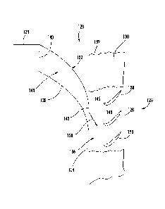
Referring to FIG. 8, a schematic view from above of an exemplary turbine
subsystem 120 using a transition duct 122 according to aspects of the
invention is
shown. The turbine subsystem 120 can include a combustor 124 and a first stage
turbine blade array 126 located longitudinally downstream of the combustor
124. The
combustor 124 is also shown radially outboard of the first stage turbine blade
array 126
relative to a central axis of a rotor (not shown) to which the first stage
turbine blade
array 126 would be affixed through a rotor disc or the like. The first stage
blade array
126 includes a plurality of blades 128 extending radially from the rotor
assembly and
spaced circumferentially to form a circular array. Only three such blades 128
are shown
in FIG. 8 schematically for ease of illustration, but the array 126 would have
additional
blades. The turbine engine subsystem 120 can also include a first stage
housing for
enclosing the first stage blade array 126. The first stage housing can include
a blade
ring 130 which is shown schematically and partially broken away to reveal the
blades
128 inside. The upstream side 134 of the blade ring 130 is preferably adapted
to
17
CA 02603130 2007-09-19
couple to the transition outlet 142. The spacing between the outlet 142 of the
transition
duct 122 and the leading edges of the blades 128 is preferably substantially
the same
as the distance between first stage vane trailing edges and the first stage
blade leading
edges used in prior systems. Alternatively, the spacing between the outlet 142
and the
leading edges of the blades 128 can be longer or shorter than prior vane-blade
spacings. The spacing depicted in FIG. 8 is not intended to be to scale and is
in fact
spaced greater than preferred spacing to facilitate illustration of the
discharge flow 150,
discussed more fully below.
The turbine engine subsystem 120 according to aspects of the invention
includes
the transition duct 122 located between the combustor 124 and the first stage
blade
array 126. The transition duct 122 includes a transition duct body 138 having
an inlet
140 located to receive a gas flow exhausted from the combustor 124 and an
outlet 142
to discharge a gas flow toward the first stage blade array 126 with an
internal passage
144 therebetween, as previously described. Only a single transition duct 122
is shown
schematically in FIG. 8, but it should be understood that the turbine engine
subsystem
120 can have multiple transition ducts, each corresponding to a combustor in a
turbine
engine. The inlet 140 can be coupled to the combustor assembly or support
structure
associated with the combustor, such as a combustor liner (not shown).
Alternatively,
the transition duct 122 can be attached to the framework of the combustion
chamber,
such as the combustion shell (not shown), and spaced from the combustor 124
but
located to receive the combustion exhaust gas flow into the inlet 140.
The outlet 142 is offset from the inlet 140 in the three coordinate directions-
-
longitudinally, radially and tangentially. The internal passage 144 is curved
between the
inlet 140 and outlet 142 at least along a portion of its length. An outlet
region of the
transition duct body 138 surrounds and defines the outlet 142 and can be
coupled to the
first stage housing, such as the blade ring 130. Alternatively, the outlet
region can be
coupled to and supported by other support structure within the combustion
chamber,
and the outlet 142 can be spaced from the blade ring 130 but located to
discharge the
gas flow into the first stage blade array 126.
18
CA 02603130 2007-09-19
The gas flow discharged from the outlet 142 is angled in the tangential
direction
146 relative to the longitudinal direction 148 as depicted by the arrow 150.
This gas
flow direction 150 signifies the predominant flow direction of the gas flow,
particularly in
its relatively uniform central region away from the structural sides and
edges. It can be
seen that this gas flow direction 150 has a longitudinal component and a
tangential
component. As discussed above, there may be a slight radial component (into or
out of
the page of the figure), but preferably this radial component is minimized or
eliminated
by relative placement of the subsystem components and the curvature of the
internal
passage 144.
Because the gas flow discharges from the transition duct outlet 142 at an
angle
150 in the tangential direction, first stage vanes can be eliminated. The
complexity and
costs of first stage vanes and their associated structural supports and
cooling systems
can likewise be avoided. Instead, the e.itlet 142 of the transition duct 122
can be offset
longitudinally, radially and tangentially from the inlet 140 with a curved
internal passage
144 therebetween to turn the gas flow to a discharge angle 150 appropriate for
direct
routing to the first stage blade array 128. The discharge angle 150 is
preferably in the
range of about 40 degrees to about 85 degrees.
A transition duct according to aspects of the invention turns the gas flow
from the
combustor to the first stage of the turbine section most significantly in the
tangential
direction, with relatively small turning in the radial direction and in the
longitudinal
direction. As a result, the thrust loads imparted on the transition duct can
be higher in
the tangential direction and lower in the radial and longitudinal direction.
Also, because
the transition duct according to aspects of the invention performs the turning
function
previously performed by first stage vanes, the mechanical and heat loads can
be high.
Accordingly, the transition duct is preferably made from materials that
exhibit high
strength properties in high temperature conditions. The transition duct can
thus be
made at least partially of ceramic matrix composite (CMC) material systems,
metals,
composite materials, and other appropriate materials. Further, known cooling
19
CA 02603130 2007-09-19
techniques, such as impingement cooling, effusion cooling, steam cooling and
forced
convection cooling, can be used.
Bearing support can be provided at the outlet region and inlet region of the
transition duct. The inlet region can be secured to the combustor assembly or
associated support structure, such as a combustor liner, as in the past. The
outlet
region is preferably supported by a braced ring support as discussed more
fully below.
Additionally, the transition duct array (see FIG. 4) can be supported between
adjacent
transition ducts by baffles, struts and the like or by additional ring
supports that are
braced to the surrounding support structure, such as the combustion chamber
shell or a
framework extending therefrom.
Referring to FIGS. 9-11, the outlet region 154a, 154b, 154c of each transition
duct can be supported by ring segments 156a, 156b, 156c that are.paced in a
circular
fashion to collectively form a support ring. Each support ring segment 156 can
have an
outer span 158 and an inner span 160, which are preferably arcuate, but can be
straight. The spans 158, 160 are joined by a central column 162 defining a
lateral
opening 164 on either side of the central column 162 into which a portion of
one of the
transition duct bodies is inserted. Two adjacent ring segments 156a, 156b
enclose a
common transition duct body 154a so that the inserted portion of the common
transition
duct body 154a is substantially surrounded.
The outlet region 154a, 154b, 154c of each transition duct body can be
equipped
with fastener posts 166 that provide adjustable fasteners, such as threaded
bolt 168, for
mounting in corresponding apertures 170 in the ring segment 156. The apertures
170
are preferably provided on support legs, like braces 172, that extend out of
one of the
spans, preferably the outer span 158. The braces 172 can provide additional
apertures
174 or other mounting structure for coupling to surrounding support structure,
such as a
blade ring or other the first stage housing of the turbine section (not
shown). Braces
172 can extend radially outwardly to couple to radially outer structure of the
first stage
housing. Braces can additionally or alternatively extend radially inwardly
from the inner
CA 02603130 2007-09-19
spans to affix to radially inward support structure of the first stage
housing. The braces
172 or other support legs are preferably dimensioned and constructed of high
strength
material to provide bearing support to primarily circumferential loads.
The use of ring segments can also assist in reducing longitudinal leakage in
the
spacing between adjacent transition ducts. As shown in FIG. 9, the junctions
176 of
adjacent ring segments such as segments 156b and 156c occur along an imaginary
line
178 across the outlet of the common transition duct body 154b, whereby leakage
between adjacent transition duct bodies is at least partially prevented. Any
spacing in a
junction 176 can be sealed by appropriate bridging material. Further, as shown
in FIG.
10, the spans 158, 160 and the column 162 of the ring segment 156 can provide
a rope
seal 180 along each lateral opening 164 to seal against the inserted
transition duct body
portion. Preferably, two such rope seals are used, but one, three or more are
also
possible.
In an alternative embodiment, as shown in FIGS. 12-14, a transition 200 may be
formed from an inlet section 202 extending downstream from an inlet 204, an
exhaust
gas diverter section 206 extending downstream from the inlet section 202, and
an outlet
section 208 extending from the exhaust gas diverter section 206 to an outlet
210. The
inlet section 202 and the outlet section 208, as shown in FIG 14., may be
substantially
linear. The exhaust gas diverter section 206 may be curved so that a gas
stream
flowing through the transition 200 may be redirected in the exhaust gas
diverter section
206. In particular, the exhaust gas diverter section 206 may be curved such
that a
longitudinal axis 212 of the inlet section 202 may be nonparallel with a
longitudinal axis
214 of the outlet section 208.
In at least one embodiment, the longitudinal axis 212 of the inlet section 202
may
be positioned at an angle 216 with a longitudinal axis 218 of the turbine
blade rotor
assembly that is between about 40 degrees and about 85 degrees. In one
embodiment,
an inlet section 202 of the transition 200 may extend from a combustor
generally
parallel to the longitudinal axis 218 of the turbine blade assembly. In such
an
21
CA 02603130 2007-09-19
embodiment, the longitudinal axis 214 of the outlet section 208 may be
positioned at an
angle of between about 40 degrees and about 85 degrees relative to the
longitudinal
axis 212 of the inlet section 202. In some embodiments, an inlet section 202
of the
transition 200 may extend from a combustor at an angle relative to the
longitudinal axis
218 of the turbine blade assembly. In such a configuration, the exhaust gas
diverter
section 206 may be curved such that the longitudinal axis 214 of the outlet
section 208
may be positioned relative to the longitudinal axis 212 of the inlet section
202 so that the
longitudinal axis 214 of the outlet section 208 is positioned between about 40
degrees
and about 85 degrees relative to the longitudinal axis 218 of the turbine
blade assembly.
Thus, in either embodiment, the exhaust gas diverter section 206 may be curved
such
that the longitudinal axis 214 of the outlet section 208 is positioned between
about 40
degrees and about 85 degrees relative to the longitudinal axis 218 of the
turbine blade
assembly. Therefore, the transition 200 may be configured to exhaust gases
from the
Vet 210 generally at an angle of between about 40 degrees and about 85 degrees
relative to the longitudinal axis 218 of the turbine blade assembly. The gas
flow
discharged from the outlet 210 substantially in a plane defined by the
longitudinal
direction and the tangential direction such that the discharged gas flow
direction has
substantially no radial component.
As shown in FIG. 12, the inlet section 202 may have a generally cylindrical,
or
round, inlet 204. The round inlet 240 may transition to a generally
trapezoidal shaped
cross-section before intersecting with the exhaust gas diverter section 206.
In at least
one embodiment, the exhaust gas diverter section 206 and the outlet section
208 may
have cross-sections with a generally trapezoidal shape. Trapezoidal shaped
cross-
sections may include constant or varying corner radii.
Thus, the invention provides a combustor transition duct that not only routes
gas
flow from a combustor to a first stage section of a turbine system, but also
turns the gas
flow in the tangential direction relative to the longitudinal direction for
direct presentation
to a first stage blade array, thereby eliminating the need for a first stage
vane row.
22
CA 02603130 2007-09-19
The foregoing description is provided in the context of a few possible
constructions of such a transition duct and associated turbine subsystem.
Thus, it will
of course be understood that the invention is not limited to the specific
details described
herein, which are given by way of example only, and that various modifications
and
alterations are possible within the scope of the invention as defined in the
following
claims.
23