Language selection

Search

Patent 2603931 Summary

Third-party information liability

Some of the information on this Web page has been provided by external sources. The Government of Canada is not responsible for the accuracy, reliability or currency of the information supplied by external sources. Users wishing to rely upon this information should consult directly with the source of the information. Content provided by external sources is not subject to official languages, privacy and accessibility requirements.

Claims and Abstract availability

Any discrepancies in the text and image of the Claims and Abstract are due to differing posting times. Text of the Claims and Abstract are posted:

  • At the time the application is open to public inspection;
  • At the time of issue of the patent (grant).
(12) Patent: (11) CA 2603931
(54) English Title: AN INJECTION DEVICE WITH AN ANGLED TRIGGER
(54) French Title: DISPOSITIF A INJECTION POURVU D'UNE DETENTE COUDEE
Status: Granted and Issued
Bibliographic Data
(51) International Patent Classification (IPC):
  • A61M 05/20 (2006.01)
(72) Inventors :
  • HABESHAW, ROSEMARY LOUISE (United Kingdom)
  • HOGWOOD, JONATHAN (United Kingdom)
(73) Owners :
  • CILAG AG INTERNATIONAL
  • CILAG GMBH INTERNATIONAL
(71) Applicants :
  • CILAG AG INTERNATIONAL (Switzerland)
  • CILAG GMBH INTERNATIONAL (Switzerland)
(74) Agent: NORTON ROSE FULBRIGHT CANADA LLP/S.E.N.C.R.L., S.R.L.
(74) Associate agent:
(45) Issued: 2014-12-23
(86) PCT Filing Date: 2006-03-21
(87) Open to Public Inspection: 2006-10-12
Examination requested: 2011-03-21
Availability of licence: N/A
Dedicated to the Public: N/A
(25) Language of filing: English

Patent Cooperation Treaty (PCT): Yes
(86) PCT Filing Number: PCT/GB2006/001023
(87) International Publication Number: GB2006001023
(85) National Entry: 2007-10-05

(30) Application Priority Data:
Application No. Country/Territory Date
0507015.6 (United Kingdom) 2005-04-06

Abstracts

English Abstract


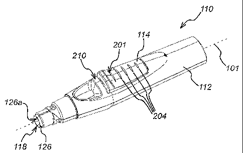
An injection device (110) comprises a housing (112) defining a first axis
(101). A drive (120) acts upon a syringe when released by a trigger (114). The
trigger is rotatable from a rest position in which the drive is retained to an
active position in which it no longer causes the drive to be so retained. The
trigger is pivotally mounted and has a surface (201) shaped such that a user
can apply a force in a direction substantially parallel to the first axis to
rotate the trigger from its rest position to its active position. Such an
injection device provides improved handling and ease of operation.


French Abstract

La présente invention concerne un dispositif à injection (110) qui comprend une enveloppe (112) définissant un premier axe (101). Un élément d'entraînement (120) agit sur une seringue lorsqu'il est libéré par une détente (114). La détente peut passer en tournant d'une position de repos sur laquelle l'élément d'entraînement est retenu à une position active permettant à l'élément d'entraînement de ne plus être ainsi retenu. La détente est montée pivotante et a une surface (201) d'une forme permettant à un utilisateur d'appliquer une force dans un sens essentiellement parallèle au premier axe afin de faire passer la détente, en la tournant, de sa position de repos à sa position active. Un dispositif à injection de ce type permet d'améliorer la manipulation et la facilité d'opération.

Claims

Note: Claims are shown in the official language in which they were submitted.


6
CLAIMS:
1. An injection device comprising:
a housing defining a first axis, and being adapted to receive a syringe having
a
discharge nozzle, so that the syringe is movable between a retracted position
in which the
discharge nozzle is contained within the housing and an extended position in
which the
discharge nozzle extends from the housing through an exit aperture;
a drive that, when activated, acts upon and moves the syringe; and
a trigger pivotable perpendicular to said first axis from a rest position, in
which it
causes the drive to be retained, to an active position, in which it no longer
causes the
drive to be so retained, thus allowing the contents of the syringe to be
discharged through
the discharge nozzle,
wherein the trigger is pivotally mounted and has a first surface, which is
concave
in part, such that a user can apply a force in a direction substantially
parallel to the first
axis to rotate the trigger from its rest position to its active position,
wherein the trigger and housing are arranged such that the force to rotate the
trigger from its rest position to its active position is applied by wrapping
of a user's hand
around the housing followed by movement of a user's hand across the housing
and over
the trigger, wherein the first surface of the trigger is located in a side of
the housing in the
rest position of the trigger.
2. The injection of claim 1, wherein the first surface is provided with a
plurality of
ridges.
3. The injection device of any one of claims 1 and 2, wherein the housing
is provided
with a second concave surface substantially opposite to the trigger so that a
user can grip
the device and apply a force to the trigger and second concave surface in a
direction
substantially parallel to the first axis.
4. The injection device of claim 3, wherein the second concave surface is
provided
with a plurality of ridges.

7
5. The injection device of any one of claims 1-4, wherein a section of the
surface of
the housing substantially opposite to the trigger includes a plurality of
ridges.
6. The injection device of any one of claims 1-5, wherein the housing
comprises an
abutment located adjacent the trigger between the trigger and the exit
aperture.

Description

Note: Descriptions are shown in the official language in which they were submitted.


CA 02603931 2013-06-03
1
AN INJECTION DEVICE WITH AN ANGLED TRIGGER
FIELD OF THE INVENTION
The present invention relates to an injection device of the type that receives
a syringe,
extends it, discharges its contents and then retracts it automatically.
BACKGROUND OF THE INVENTION
Previously known injection devices are shown in WO 95/35126 and EP-A-0 516 473
and
tend to employ a drive spring and a trigger that, when activated, causes the
drive spring to
act on the syringe when a releasable locking mechanism is also engaged.
The trigger acts is rotatable about an axis so that when it is depressed at a
first end, a
second end (which normally engages with the drive spring) is also rotated,
thereby
releasing the drive spring, extending the syringe and discharging its
contents. The trigger
is generally mounted in the side of the housing of the injection device
parallel to the
longitudinal axis of the body of the injection device. The trigger is rotated
by pressing
down on the trigger at one end in a direction towards the housing.
A problem with such devices is that the action of pressing down on the trigger
towards the
housing can be difficult if the device is being held in one hand. This poses
significant
problems for sick and ill users of the injection device, for example users
suffering from
rheumatoid arthritis.
SUMMARY OF THE INVENTION
The injection device of the present invention is designed to deal with this
and other
problems.
1

CA 02603931 2007-10-05
WO 2006/106292 PCT/GB2006/001023
2
In view of the foregoing and in accordance with a first aspect of the
invention, there is
provided an injection device comprising:
a housing defining a first axis, and being adapted to receive a syringe having
a
discharge nozzle, so that the syringe is movable between a retracted position
in which the
discharge nozzle is contained within the housing and an extended position in
which the
discharge nozzle extends from the housing through an exit aperture;
a drive that is acted upon and in turn acts upon the syringe; and
a trigger rotatable from a rest position, in which it causes the drive to be
retained, to
an active position, in which it no longer causes the drive to be so retained,
thus allowing
the contents of the syringe to be discharged through the discharge nozzle,
wherein the trigger is pivotally mounted and has a surface shaped such that a
user
can apply a force in a direction substantially parallel to the first axis to
rotate the trigger
from its rest position to its active position.
By having the trigger operable so that a force can be applied in a direction
which is
substantially parallel to the first axis, the trigger does not need to be
pushed into the side of
the housing to activate it. This way, the injection device can be held and
operated with one
hand by sliding the hand down the housing and over the trigger as the exit
aperture is
pushed against a user's body.
Preferably, the surface is a first concave surface.
In one embodiment of the invention, the surface is provided with a plurality
of ridges.
Preferably, the housing is provided with a second concave surface
substantially opposite to
the trigger so that a user can grip the device and apply a force to the
trigger and second
concave surface in a direction substantially parallel to the first axis.
In one embodiment of the invention, the housing comprises an abutment located
adjacent
the trigger between the trigger and the exit aperture.
In one embodiment of the invention, the second concave surface is provided
with a
plurality of ridges.

CA 02603931 2013-06-03
2a
In a further aspect, there is provided an injection device comprising:
a housing defining a first axis, and being adapted to receive a syringe having
a
discharge nozzle, so that the syringe is movable between a retracted position
in which the
discharge nozzle is contained within the housing and an extended position in
which the
discharge nozzle extends from the housing through an exit aperture;
a drive that, when activated, acts upon and moves the syringe; and
a trigger pivotable perpendicular to said first axis from a rest position, in
which it
causes the drive to be retained, to an active position, in which it no longer
causes the drive to
be so retained, thus allowing the contents of the syringe to be discharged
through the
discharge nozzle,
wherein the trigger is pivotally mounted and has a surface, which is concave
in part,
such that a user can apply a force in a direction substantially parallel to
the first axis to rotate
the trigger from its rest position to its active position,
wherein the trigger and housing are arranged such that the force to rotate the
trigger
from its rest position to its active position is applied by wrapping of a
user's hand around the
housing followed by movement of a user's hand across the housing and over the
trigger,
wherein the first surface of the trigger is located in a side of the housing
in the rest position
of the trigger.

CA 02603931 2007-10-05
WO 2006/106292 PCT/GB2006/001023
3
BRIEF DESCRIPTION OF THE DRAWINGS
The invention will now be described by way of example with reference to the
accompanying drawings, in which:
Figure 1 shows a perspective view of an injection device according to the
present
invention;
Figure 2 shows an alternative perspective view of an injection device
according to the
present invention; and
Figure 3 shows a side view of the injection device of figures 1 and 2 with an
upper section
of the housing of the injection device removed.
DETAILED DESCRIPTION OF THE DRAWINGS
Figures 1 to 3 show an injection device 110 according to a first embodiment of
the present
invention. The injection device 110 has an injection device housing 112 and a
longitudinal
axis 101.
A syringe (not shown) is contained in the housing 112. The injection device
110
comprises trigger 114 and a releasable locking mechanism 116. The trigger 114
has a first
end 114a and a second end 114b. The trigger 114 is rotatable about a pivot 115
from a rest
position to an active position. The second end 114b of the trigger 114
connects with a
drive coupling 121 which is acted upon by a drive spring 120. The drive
coupling 121 is in
communication with the syringe.
Rotation of the trigger 114 about the pivot 115 in a direction R (i.e.
downwards into the
housing 112 at its first end 114a) causes the second end 114b of the trigger
114 to
disengage from the drive coupling J21, thereby letting the drive spring _120
drive the
syringe (via the drive coupling 121) along the longitudinal axis 101 and out
of an aperture
118 in the housing 112.

CA 02603931 2007-10-05
WO 2006/106292 PCT/GB2006/001023
4
The releasable locking mechanism 116 is in communication with sliding sleeve
126 which
protrudes, when in a first position, from the aperture 118 in the housing 112.
The locking
mechanism 116 is deactivated by movement of the sliding sleeve 126 along the
longitudinal axis 101 into the housing 112 into a second position.
A first end 126a of the sliding sleeve 126 can be placed against a body into
which drug is
being delivered, thereby deactivating the releasable locking mechanism 116 and
allowing
the trigger 114 to rotate in direction R from its rest position to its active
position.
The trigger 114 is shaped in such a way that there is a section of surface 201
at an angle to
the longitudinal axis 101 of the injection device 110. Hence, rotation of the
trigger 114
can take place by exertion of force in a direction which is not necessarily
perpendicular to
the longitudinal axis. This way, a rotational force can still be exerted on
the trigger 114,
even if that force is not applied inwards towards the housing 112.
In the embodiment of the invention shown in Figures 1 and 3, the surface 201
is shaped
concavely.
The hand of a user of the injection device 110 can be wrapped around the
housing 112 and
the injection device 110 forced against the user's body so that the sliding
sleeve 126 causes
the locking mechanism 116 to disengage. The trigger 114 can now be activated
by
movement of the user's hand across the housing 112 and over the trigger 114 so
that a force
having a component in the direction of the longitudinal axis 101 is applied to
the trigger
114 causing it to rotate.
The housing 112 also comprises a ridge 210 (or an abutment) located behind the
trigger
114 towards the exit aperture 118 of the housing 112. The ridge acts as a stop
surface to
prevent a user's hand moving further down the housing 112 once the trigger 114
has been
activated. This way, the injection device 110 can be held firmly against a
user's body after
activation of the trigger 114 and whilst the contents of the syringe is_being
dispelled into
their body.

CA 02603931 2007-10-05
WO 2006/106292 PCT/GB2006/001023
The housing 112 comprises a second concave surface 202 located substantially
opposite to
the trigger 114. Thus, the user's hand is prevented from moving further down
the housing
112 once the trigger 114 has been activated.
The surface 201 and a section of the surface of the housing opposite the
trigger 114 both
comprise ridges 204 which act as grips for the user's hand.
It will of course be understood that the present invention has been described
above purely
by way of example and modifications of detail can be made within the scope of
the
invention.

Representative Drawing
A single figure which represents the drawing illustrating the invention.
Administrative Status

2024-08-01:As part of the Next Generation Patents (NGP) transition, the Canadian Patents Database (CPD) now contains a more detailed Event History, which replicates the Event Log of our new back-office solution.

Please note that "Inactive:" events refers to events no longer in use in our new back-office solution.

For a clearer understanding of the status of the application/patent presented on this page, the site Disclaimer , as well as the definitions for Patent , Event History , Maintenance Fee  and Payment History  should be consulted.

Event History

Description Date
Common Representative Appointed 2019-10-30
Grant by Issuance 2014-12-23
Inactive: Cover page published 2014-12-22
Pre-grant 2014-10-08
Inactive: Final fee received 2014-10-08
Notice of Allowance is Issued 2014-04-10
Letter Sent 2014-04-10
Notice of Allowance is Issued 2014-04-10
Inactive: QS passed 2014-04-08
Inactive: Approved for allowance (AFA) 2014-04-08
Amendment Received - Voluntary Amendment 2014-03-27
Inactive: S.30(2) Rules - Examiner requisition 2013-09-27
Amendment Received - Voluntary Amendment 2013-06-03
Inactive: S.30(2) Rules - Examiner requisition 2012-12-04
Amendment Received - Voluntary Amendment 2012-08-28
Amendment Received - Voluntary Amendment 2012-01-30
Amendment Received - Voluntary Amendment 2011-07-18
Amendment Received - Voluntary Amendment 2011-05-18
Letter Sent 2011-03-30
Request for Examination Requirements Determined Compliant 2011-03-21
Request for Examination Received 2011-03-21
All Requirements for Examination Determined Compliant 2011-03-21
Amendment Received - Voluntary Amendment 2010-11-15
Letter Sent 2009-07-16
Inactive: Delete abandonment 2009-07-16
Inactive: Abandoned - No reply to Office letter 2009-03-23
Inactive: Correspondence - Transfer 2009-01-28
Inactive: Transfer information requested 2008-12-22
Inactive: Correspondence - Transfer 2008-11-04
Inactive: Office letter 2008-09-08
Inactive: Single transfer 2008-06-26
Correct Applicant Request Received 2008-06-26
Inactive: Declaration of entitlement/transfer requested - Formalities 2007-12-27
Inactive: Cover page published 2007-12-21
Inactive: Notice - National entry - No RFE 2007-12-19
Inactive: First IPC assigned 2007-11-06
Application Received - PCT 2007-11-05
National Entry Requirements Determined Compliant 2007-10-05
Application Published (Open to Public Inspection) 2006-10-12

Abandonment History

There is no abandonment history.

Maintenance Fee

The last payment was received on 2014-02-24

Note : If the full payment has not been received on or before the date indicated, a further fee may be required which may be one of the following

  • the reinstatement fee;
  • the late payment fee; or
  • additional fee to reverse deemed expiry.

Patent fees are adjusted on the 1st of January every year. The amounts above are the current amounts if received by December 31 of the current year.
Please refer to the CIPO Patent Fees web page to see all current fee amounts.

Owners on Record

Note: Records showing the ownership history in alphabetical order.

Current Owners on Record
CILAG AG INTERNATIONAL
CILAG GMBH INTERNATIONAL
Past Owners on Record
JONATHAN HOGWOOD
ROSEMARY LOUISE HABESHAW
Past Owners that do not appear in the "Owners on Record" listing will appear in other documentation within the application.
Documents

To view selected files, please enter reCAPTCHA code :


To view images, click a link in the Document Description column (Temporarily unavailable). To download the documents, select one or more checkboxes in the first column and then click the "Download Selected in PDF format (Zip Archive)" or the "Download Selected as Single PDF" button.

List of published and non-published patent-specific documents on the CPD .

If you have any difficulty accessing content, you can call the Client Service Centre at 1-866-997-1936 or send them an e-mail at CIPO Client Service Centre.

({010=All Documents, 020=As Filed, 030=As Open to Public Inspection, 040=At Issuance, 050=Examination, 060=Incoming Correspondence, 070=Miscellaneous, 080=Outgoing Correspondence, 090=Payment})


Document
Description 
Date
(yyyy-mm-dd) 
Number of pages   Size of Image (KB) 
Description 2007-10-04 5 202
Representative drawing 2007-10-04 1 12
Drawings 2007-10-04 2 44
Abstract 2007-10-04 2 67
Claims 2007-10-04 2 55
Description 2013-06-02 6 233
Claims 2013-06-02 2 51
Claims 2014-03-26 2 51
Representative drawing 2014-11-26 1 12
Notice of National Entry 2007-12-18 1 194
Courtesy - Certificate of registration (related document(s)) 2009-07-15 1 102
Reminder - Request for Examination 2010-11-22 1 117
Acknowledgement of Request for Examination 2011-03-29 1 189
Commissioner's Notice - Application Found Allowable 2014-04-09 1 161
PCT 2007-10-04 5 168
Correspondence 2007-12-18 1 26
Correspondence 2008-09-07 1 18
Correspondence 2008-06-25 2 67
Correspondence 2008-12-21 1 22
Fees 2009-03-29 2 55
Correspondence 2014-10-07 2 69