Language selection

Search

Patent 2604029 Summary

Third-party information liability

Some of the information on this Web page has been provided by external sources. The Government of Canada is not responsible for the accuracy, reliability or currency of the information supplied by external sources. Users wishing to rely upon this information should consult directly with the source of the information. Content provided by external sources is not subject to official languages, privacy and accessibility requirements.

Claims and Abstract availability

Any discrepancies in the text and image of the Claims and Abstract are due to differing posting times. Text of the Claims and Abstract are posted:

  • At the time the application is open to public inspection;
  • At the time of issue of the patent (grant).
(12) Patent Application: (11) CA 2604029
(54) English Title: METHOD AND MEANS FOR PROVIDING TIME DELAY IN DOWNHOLE WELL OPERATIONS
(54) French Title: PROCEDE ET MOYEN DESTINES A FOURNIR UN RETARD DANS DES OPERATIONS DE PUITS DE FOND DE TROU
Status: Deemed Abandoned and Beyond the Period of Reinstatement - Pending Response to Notice of Disregarded Communication
Bibliographic Data
(51) International Patent Classification (IPC):
  • E21B 31/113 (2006.01)
(72) Inventors :
  • AKSELBERG, FRANK OVE (Norway)
(73) Owners :
  • WELL INNOVATION AS
(71) Applicants :
  • WELL INNOVATION AS (Norway)
(74) Agent: SMART & BIGGAR LP
(74) Associate agent:
(45) Issued:
(86) PCT Filing Date: 2006-04-07
(87) Open to Public Inspection: 2006-10-12
Availability of licence: N/A
Dedicated to the Public: N/A
(25) Language of filing: English

Patent Cooperation Treaty (PCT): Yes
(86) PCT Filing Number: PCT/NO2006/000129
(87) International Publication Number: NO2006000129
(85) National Entry: 2007-10-05

(30) Application Priority Data:
Application No. Country/Territory Date
20051733 (Norway) 2005-04-08
20053675 (Norway) 2005-07-29

Abstracts

English Abstract


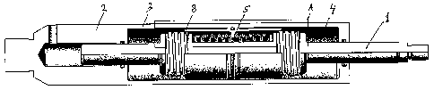
The present invention relates to a means and method for providing hydraulic
load compensated time delay in downhole well operations. The means according
to the invention is characterized in that it includes a piston stem (1)
enclosed by a piston housing (2), wherein the means is adapted in such a
manner that an axial force, acting either in the direction of stretch or in
the direction of compression, causes a pressure buildup in one of two
hydraulic chambers (3, 4) which are each filled with an incompressible liquid
and which are mutually connected through one or more throttle orifices (8),
wherein a sideways floating, supported piston sleeve (5) is arranged between
the piston stem (1 ) and the piston housing (2), wherein the piston sleeve (5)
is adapted to control the differential pressure across the throttle orifice(s)
(8) in such a manner that an increasing axial force acting on the means will,
in a predetermined manner, increase the differential pressure across the
throttle orifice(s) and hence delay the flow-through of the incompressible
liquid from one of the to hydraulic chambers (3, 4) to the second chamber (4,
3), which also causes a predetermined delay of the relative movement between
the piston stem (1) and the piston housing (2).


French Abstract

La présente invention concerne un moyen et un procédé pour fournir un retard compensé en charge hydraulique dans des opérations de puits de fond de trou. Le moyen selon l~invention est caractérisé en ce qu~il comprend une tige de piston (1) enfermée par un logement de piston (2), le moyen étant adapté de telle manière qu~une force axiale, agissant soit dans la direction d~étirement soit dans la direction de compression, entraîne une accumulation de pression dans une de deux chambres hydraulique (3, 4) qui sont chacune remplies avec un liquide incompressible et qui sont mutuellement raccordées par l'intermédiaire d~un ou plusieurs orifices d~étranglement (8), un manchon de piston supporté flottant latéralement (5) étant agencé entre la tige de piston (1) et le logement de piston (2), le manchon de piston (5) étant adapté pour contrôler la pression différentielle à travers le ou les orifice(s) d~étranglement (8) de manière telle qu~une force axiale de plus en plus importante agissant sur le moyen augmentera, de manière prédéterminée, la pression différentielle à travers le ou les orifice(s) d~étranglement et donc retardera le débit du liquide incompressible d~une première des deux chambres hydrauliques (3, 4) à la seconde chambre (4, 3), qui entraîne également un délai prédéterminé du mouvement relatif entre la tige de piston (1) et le logement de piston (2).

Claims

Note: Claims are shown in the official language in which they were submitted.


7
CLAIMS
1. A means for providing a hydraulic load compensated time delay in downhole
well operations,
characterized in that it comprises a piston stem (1) enclosed by a piston
housing (2), wherein the means is adapted in such a manner that an axial
force,
acting either in the direction of stretch or in the direction of compression,
causes a
pressure buildup in one of two hydraulic chambers (3, 4) which are each filled
with an
incompressible liquid and which are mutually connected through one or more
throttle
orifices (8), wherein a sideways floating, supported piston sleeve (5) is
arranged
between the piston stem (1) and the piston housing (2), wherein the piston
sleeve (5)
is adapted to control the differential pressure across the throttle orifice(s)
(8) in such
a manner that an increasing axial force acting on the means will, in a
predetermined
manner, increase the differential pressure across the throttle orifice(s) and
hence
delay the flow-through of the incompressible liquid from one of the to
hydraulic
chambers (3, 4) to the second chamber (4, 3), which also causes a
predetermined
delay of the relative movement between the piston stem (1) and the piston
housing
(2).
2. The means of claim 1,
characterized in that the piston sleeve (5) is adapted to close one or more
throttle orifices (8) on increasing axial pressure, and thus increases the
flow
resistance of the incompressible liquid.
3. The means of claim 1,
characterized in that the piston sleeve (5) is adapted to reduce the size of
one or more throttle orifices (8) on increasing axial pressure, and thus
increases the
flow resistance of the incompressible liquid.
4. The means of claim 1,
characterized in that the piston sleeve (5) defines one or more throttle
orifices (8) in the form of one or more channels, the piston sleeve (5) being
designed
in such a manner that the length of the channel(s) are extended on increasing
axial
pressure, and thus increases the flow resistance of the incompressible liquid.

8
5. The means of claim 4,
characterized in that the channel(s) has/have a helical shape.
6. The means of claims 4 or 5,
characterized in that the channel(s) and the piston sleeve (5) are shaped in
such a manner that at the flow through the throttle orifice (8) at least some
of the time
is laminar.
7. The means of claims 1 - 6,
characterized in that the area of the throttle orifice(s) (8) at any time is
adjusted to allow a constant liquid flow through the currently non-blocked
throttle
orifice(s) (8), independent of the axial force acting between the piston stem
(1) and
the piston housing (2).
8. The means of claims 1 - 7,
characterized in that the area of the throttle orifice(s) (8) at any time is
adjusted to obtain a constant relative movement between the piston stem (1)
and the
piston housing (2), independent of the axial force acting between the piston
stem (1)
and the piston housing (2).
9. A method for providing hydraulic load compensated time delay in downhole
well operations,
characterized in that an axial force acting between a piston stem (1) and a
piston housing (2) enclosing the piston stem (1) causes a pressure buildup in
one of
two hydraulic chambers (3, 4) which are each filled with an incompressible
liquid,
wherein a relative movement between the piston stem (1) and the piston housing
(2)
causes a portion of the incompressible liquid to be displaced from one of the
chambers (3) to the other chamber (4), or vice versa, wherein a sideways
floating,
supported piston sleeve (5) arranged between the piston stem (1) and the
piston
housing (2) causes the covering or uncovering of one or more throttle orifices
(8),
wherein an axial movement between the piston stem (1) and the piston housing
(2),
respectively, caused by the axial force action forces a liquid flow through
the throttle
orifice(s) 8 of the piston sleeve (5), whereby a differential pressure across
the throttle

9
orifice(s) (8) is created which directly depends on the magnitude of the axial
force
acting between the piston stem (1) and the piston housing (2), the
differential
pressure caused by which affecting the floating, supported piston sleeve (5)
in such a
manner that it is given an axial movement relative to both the piston stem (1)
and the
piston housing (2), the relative axial movement between the piston sleeve (5)
and the
piston stem (1) and/or the piston housing (2) affecting the area of the
throttle
orifice(s) (8) and thereby the built-up differential pressure across the
throttle orifice(s)
(8).
10. The method of claim 9,
characterized in that the throttle orifice(s) (8) is/are comprised of holes,
slots, channels, or a combination thereof.
11. The method of claim 10,
characterized in that the channel(s) preferably has/have a helical shape.
12. The method of claims 9 - 11,
characterized in that the area of the throttle orifice(s) (8) is adjusted to
allow
a constant liquid flow through the currently non-blocked throttle orifice(s)
(8).
13. The method of claims 9 - 12,
characterized in that the area of the throttle orifice(s) (8) is adjusted to
obtain a constant relative movement between the piston stem (1) and the piston
housing (2), independent of the axial force acting between the piston stem (1)
and
the piston housing (2).

Description

Note: Descriptions are shown in the official language in which they were submitted.


CA 02604029 2007-10-05
WO 2006/107215 PCT/N02006/000129
1
Method and means for providing time delay in downhole well operations
The present invention relates to a means for hydraulic load compensated time
delay.
In downhole well operations, there is often a need for a means that is able to
provide
a predetermined time delay in connection with an actuation or initiation of a
tool that
is to perform some work in the well. Often, it is only possible to actuate
such means
using tensile and/or compressive forces, for example through wireline
operations.
io It is further desirable that the time delay is predictable, which can
present a challenge
when the forces applied to the time delay means, using a long wireline, for
example,
may be difficult to control. It would be advantageous to be able to minimize
the
factors that could affect the duration of the time delay obtained in each
case, and
thereby simplify the calculation of the holding times necessary to effect a
particular
tool function. By compensating the means that creates the time delay for
variations in
the forces that are applied to the device, it is possible to achieve an as
constant, and
thereby predictable, time delay as possible.
An example of a mechanically operated tool that may be actuated using a time
delay
means is a jar. In the actuation of a jar, a means is frequently used that is
tensioning.
a spring, for example, which spring is released when it has a certain
pretension
and/or when a predetermined time period has elapsed. A wireline may be used
for
tensioning the spring, but the time needed for tensioning the spring is
difficult to
control because the force that is transferred through the wireline may drop
off due to
friction, stretch, and the like. Moreover, the mechanism generating the force
is poorly
controllable and hence unsuitable for fine adjustments. Thus, there is a need
for
means that control the tensioning of the spring in a jar, for example, so that
the
tensioning time is largely independent of the tensioning force and any pulls
or yanks
that may occur. Therefore, it is desired to provide a system that gives a
small
resistance when the applied force is weak and that gives a larger resistance
when
the applied force is strong, wherein the resistance profile should be as
proportional
as possible to the applied force and fast reacting in order to absorb any
sudden
vigorous pulls.

CA 02604029 2007-10-05
WO 2006/107215 PCT/N02006/000129
2
The present invention provides a means that meets the above-mentioned needs,
the
means being characterized in the features set forth in the characterizing part
of claim
1. Additional advantageous features and embodiments are set forth in the
dependent
claims.
In the following, a detailed description of a preferred embodiment of the
present
invention is given, with reference to the accompanying drawings, wherein:
Fig. 1 a shows a sketch of a first embodiment of the present invention,
Fig. 1 b shows a section A of the embodiment shown in Fig. 1 a,
Figs. 2a-c show a sequence of the operation of the embodiment shown in Fig. 1
a,
Fig. 3a shows a sketch of a second embodiment of the present invention,
Fig. 3b shows a section B of the embodiment shown in Fig. 3a, and
Figs. 4a-c show a sequence of the operation of the embodiment shown in Fig.
3a.
The present invention provides a time delaying hydraulic system that is based
on the
flow characteristics of substantially Newtonian fluids.
Figs. 1 a and 3a show a section of two variants of a tool providing a
hydraulic load
compensated time delay. An axial, relative force acting between a piston stem
1 and
a cylindrical piston housing 2 enclosing the piston stem 1 causes a pressure
buildup
in one of two hydraulic chambers 3, 4 which are each filled with an
incompressible
liquid, and a relative movement between the piston stem 1 and the piston
housing 2
causes liquid to be displaced from one of the chambers 3 to the other chamber
4, or
vice versa. Between the piston stem 1 and the piston housing 2 a sideways
floating
hydraulic piston sleeve 5 is arranged, supported by a spring 6 on each side of
a
piston sleeve lug 7, which piston sleeve 5, on an axial movement between the
piston
stem 1 and the piston housing 2, respectively, causes a liquid flow through a
throttle

CA 02604029 2007-10-05
WO 2006/107215 PCT/N02006/000129
3
orifice 8, whereby a differential pressure across the throttle orifice 8 is
created which
is directly dependent on the magnitude of the axial force action, the
resulting
pressure of which affects the pistori sleeve 5 in such a manner that it is
given an axial
movement relative to both the piston stem 1 and the piston housing 2. On the
relative
axial movement the area and/or length of the throttle orifice 8 may vary, as
the
design of the area and/or length of the throttle orifice 8 enables the tool to
respond to
a variable force action as optimally as possible.
According to one embodiment, the differential pressure is controlled by
adjusting the
io length of the throttle orifice 8. According to a preferred embodiment, this
may be
accomplished by forming a helical channel around the piston stem, for example,
the
position of the piston sleeve 5 above the helical channel determining the
effective
channel length for the hydraulic fluid. This is shown in figures la-b and 2a-
c. By
forcing the hydraulic fluid to pass through several windings of the helical
channel
when the acting force is stronger, the length of, and thereby the differential
pressure
across, the throttle orifice 8 will increase, which will result in that the
predetermined
time delay is obtained independently of the strength and profile of the acting
force.
It is understood that the channels may also be arranged on the piston sleeve 5
or on
the piston housing 2.
It is well known that the flow resistance of a pipe depends on whether the
flow is
laminar or turbulent. As long as the flow is laminar, the ratio between the
flow and the
flow resistance will be linearly increasing. When the laminar flow collapses
and
becomes turbulent, the flow resistance is significantly reduced. In the
present
invention, according to one embodiment, the linear properties applicable to
laminar
flow conditions may be used.
The flow resistance R of a pipe may be expressed by the equation:
R 8r/L
1L7'
4where L is the pipe length, q is the fluid viscosity, and r is the pipe
diameter. As can
be seen, R increases linearly with the pipe length and increases to the 4th
power

CA 02604029 2007-10-05
WO 2006/107215 PCT/N02006/000129
4
with a decreasing diameter. By letting the incompressible liquid pass through
a pipe
having a greater length and/or smaller radius on a stronger force action, a
progressive damping is provided. By continuously and dynamically adjusting the
ratio
between the acting force and the length and/or radius of the throttle orifice;
a
predetermined time delay independent of the strength and profile of the force
action
may be obtained.
It is not essential that the throttle orifice 8 is shaped as a helical
channel. It may be
shaped in any preferred configuration, but a helical channel results in a
compact
design wherein it is easy to provide a sufficient and accurate channel length
that
thereby effects the adequate resistance for a given applied force.
According to another embodiment of the present invention, the resistance of
the tool
will increase in that the piston sleeve 5 covers, and hence reduces, the area
of one
or more throttle orifices 8, to thereby increase the differential pressure
significantly.
Figures 3a-b and 4a-c show an embodiment wherein the throttle orifices 8 are
constituted by slots. In the embodiment shown, the slots are formed in the
piston
sleeve 5, being milled out diagonally with respect to the axial direction of
the tool. It is
2o understood that the slots may also be formed lengthwise or crosswise, and
that the
width of the slots may be varying, having a taper, for example.. It is also
possible to
provide a number of holes of same or varying size and/or having varying
spacing with
respect to the axial displacement of the piston sleeve 5.
The accompanying drawings show a double action tool, i.e. the direction of the
force
applied to the tool is indifferent. A single action tool that only functions
in tensile
forces will work equally well, and will in some cases be preferable.
The tool includes a piston stem 1 enclosed by a piston housing 2, and an axial
force,
acting either in the direction of stretch or in the direction of compression,
or
alternatively only in one of the directions, causes a pressure buildup in one
of two
hydraulic chambers 3, 4. The chambers 3, 4 are each filled with an
incompressible
liquid and are mutually connected through one or more throttle orifices 8. A
sideways
floating, supported piston sleeve 5 is provided between the piston stem 1 and
the

CA 02604029 2007-10-05
WO 2006/107215 PCT/N02006/000129
piston housing 2. The piston sleeve 5 helps regulating the differential
pressure
across the throttle orifice(s) 8 in such a manner that an increasing axial
force acting
on'the arrangement will, in a predetermined manner, increase the differential
pressure across the throttle orifice(s) and hence delay the flow-through of
the
5 incompressible liquid from one of the two hydraulic chambers 3, 4 to the
other
chamber 4, 3, which also causes a predetermined delay of the relative movement
between the piston stem 1 and the piston housing 2. On the application of
force, a
relative movement between the piston housing 2 and the piston stem 1 with no
time
delay will occur, the piston sleeve being displaced relative to the housing 2
and stem
1 and balancing between a spring and the hydraulic pressure, for example. The
greater the applied force, the greater the stroke of the piston sleeve. In
order to
compensate for the lost stroke length, the inclination of the channels, slots,
or
grooves may be made smoothly increasing to thereby obtain a substantially
constant
time delay independent of the magnitude of the applied force. If holes are
provided,
their spacing may be varied in order to obtain the same, substantially
constant time
delay independent of the magnitude of the applied force.
According to one embodiment, the piston sleeve 5 is adapted to close one or
more
throttle orifices 8 on increasing axial pressure, and thus increase the flow
resistance
of the incompressible liquid.
According to another embodiment, the piston sleeve 5 is adapted to reduce the
size
of one or more throttle orifices 8 on increasing axial pressure, and thus
increase the
flow resistance of the incompressible liquid.
Figures la-b and 2a-c shows an embodiment wherein an applied force will cause
the
piston sleeve 5 to define one or more throttle orifices 8 in the form of one
or more
channels, the piston sleeve 5 being adapted so that the length of the
channei(s) are
extended on increasing axial pressure and hence to increase the flow
resistance of
the incompressible liquid. In this case, the channel or channels have a
helical shape,
and the channel(s) and the piston sleeve 5 should preferably be shaped in such
a
manner that the flow through the throttle orifice 8 is laminar.
It is understood that the area of the throttle orifice(s) 8 at any time is
adjusted to allow

CA 02604029 2007-10-05
WO 2006/107215 PCT/N02006/000129
6
a constant liquid flow through the currently non-blocked throttle orifice(s),
independent of the axial force acting between the piston stem 1 and the piston
housing 2, to thereby provide the desired time delay.
The area of the throttle orifice(s) 8 may at any time also be adjusted to
obtain a
constant relative movement between the piston stem 1 and the piston housing 2,
independent of the axial force acting between the piston stem 1 and the piston
housing 2.
An alternative application of the present invention is as a constant flow
valve.

Representative Drawing
A single figure which represents the drawing illustrating the invention.
Administrative Status

2024-08-01:As part of the Next Generation Patents (NGP) transition, the Canadian Patents Database (CPD) now contains a more detailed Event History, which replicates the Event Log of our new back-office solution.

Please note that "Inactive:" events refers to events no longer in use in our new back-office solution.

For a clearer understanding of the status of the application/patent presented on this page, the site Disclaimer , as well as the definitions for Patent , Event History , Maintenance Fee  and Payment History  should be consulted.

Event History

Description Date
Application Not Reinstated by Deadline 2012-04-10
Time Limit for Reversal Expired 2012-04-10
Inactive: Abandon-RFE+Late fee unpaid-Correspondence sent 2011-04-07
Deemed Abandoned - Failure to Respond to Maintenance Fee Notice 2011-04-07
Inactive: Declaration of entitlement/transfer requested - Formalities 2008-01-02
Inactive: Cover page published 2007-12-31
Inactive: Notice - National entry - No RFE 2007-12-27
Inactive: Declaration of entitlement - Formalities 2007-11-27
Inactive: First IPC assigned 2007-11-07
Application Received - PCT 2007-11-06
National Entry Requirements Determined Compliant 2007-10-05
Application Published (Open to Public Inspection) 2006-10-12

Abandonment History

Abandonment Date Reason Reinstatement Date
2011-04-07

Maintenance Fee

The last payment was received on 2010-03-09

Note : If the full payment has not been received on or before the date indicated, a further fee may be required which may be one of the following

  • the reinstatement fee;
  • the late payment fee; or
  • additional fee to reverse deemed expiry.

Patent fees are adjusted on the 1st of January every year. The amounts above are the current amounts if received by December 31 of the current year.
Please refer to the CIPO Patent Fees web page to see all current fee amounts.

Fee History

Fee Type Anniversary Year Due Date Paid Date
Basic national fee - standard 2007-10-05
MF (application, 2nd anniv.) - standard 02 2008-04-07 2008-03-17
MF (application, 3rd anniv.) - standard 03 2009-04-07 2009-03-20
MF (application, 4th anniv.) - standard 04 2010-04-07 2010-03-09
Owners on Record

Note: Records showing the ownership history in alphabetical order.

Current Owners on Record
WELL INNOVATION AS
Past Owners on Record
FRANK OVE AKSELBERG
Past Owners that do not appear in the "Owners on Record" listing will appear in other documentation within the application.
Documents

To view selected files, please enter reCAPTCHA code :


To view images, click a link in the Document Description column (Temporarily unavailable). To download the documents, select one or more checkboxes in the first column and then click the "Download Selected in PDF format (Zip Archive)" or the "Download Selected as Single PDF" button.

List of published and non-published patent-specific documents on the CPD .

If you have any difficulty accessing content, you can call the Client Service Centre at 1-866-997-1936 or send them an e-mail at CIPO Client Service Centre.

({010=All Documents, 020=As Filed, 030=As Open to Public Inspection, 040=At Issuance, 050=Examination, 060=Incoming Correspondence, 070=Miscellaneous, 080=Outgoing Correspondence, 090=Payment})


Document
Description 
Date
(yyyy-mm-dd) 
Number of pages   Size of Image (KB) 
Drawings 2007-10-04 4 186
Description 2007-10-04 6 280
Claims 2007-10-04 3 127
Abstract 2007-10-04 1 74
Representative drawing 2007-12-27 1 13
Reminder of maintenance fee due 2007-12-26 1 112
Notice of National Entry 2007-12-26 1 194
Reminder - Request for Examination 2010-12-07 1 117
Courtesy - Abandonment Letter (Maintenance Fee) 2011-06-01 1 172
Courtesy - Abandonment Letter (Request for Examination) 2011-07-13 1 164
PCT 2007-10-04 3 108
Correspondence 2007-12-26 1 25
Correspondence 2007-11-26 2 53
Fees 2009-03-19 1 35