Note: Descriptions are shown in the official language in which they were submitted.
CA 02604194 2007-10-09
WO 2006/132731 PCT/US2006/016782
ROLL OF PAPERBAND
TECHNICAL FIELD
This invention relates'to a roll of paperband wherein the paperband includes
longitudinal indentations and transverse undulations to create a corrugated
structure to
control stiffness and flexibility of the band as desired.
BACKGROUND ART
It is a common practice in the papermaking and packaging industries to employ
a
paperband or strap that is loaded into a channel of a track assembly and then
removed
rapidly out of the channel and employed to cut and spool a web of paper onto
an empty
spool or to be used to wrap around and secure a load, container or a bundle of
material.
Because the paperband should be stiff enough to be pushed into the channel
from one end
thereof, the band may twist or otherwise be distorted or separated during
upward movment
that is accomplished by a"stripping" action during removal from the paperband
track
assembly. This becomes a very important consideration in those applications
where the
width of the channel opening is made less than the width of the band or tape
and the lower
tape-carrying guide way of the channel in order to cover and carry the tape.
An improved
paperband is disclosed herein that greatly reduces the distortion and crimping
common to
prior art paperbands, reduces the wear on the guide way channel and its cover,
and also
reduces the separation of layers in some bands made from multiple layers.
Examples of the prior art include U.S. Patent No. 5,816,526, which discloses
multi-
ply folded strip held together.by adhesive. U.S. Patent No. 3,126,312
discloses a plurality
of elongate members aligned in a plane and held together by adhesive. U.S.
Patent No.
4,414,258 discloses a woven ribbon made of flat strips and weft filaments,
which are held in
place by adhesive.
U.S. Patent Publication No. 2004/0131825 Al (July 8, 2004) discloses a strap
constructed of a double layer of elongated paper elements secured with
adhesive on at
least a portion of the strap.
None of the above-described paper devices is satisfactory for use in a
paperband
track assembly beneath wide paper machines for the reason that they do not
have the
required stiffness for such use.
DISCLOSURE OF THE INVENTION
In one aspect of the present invention there is provided a roll of paperband
adaptable for use in paper web cutting and tum-up systems or for use in
baling, the paper-
CA 02604194 2007-10-09
WO 2006/132731 PCT/US2006/016782
2
band comprising an elongate multi-ply board having upper and lower surfaces,
and a center
portion and spaced reduced side portions, each side portion having an inside
edge portion
and an outside edge portion, each inside edge portion being defined by an
elongate
longitudinal first groove between the center portion and respective side
portion. Each side
portion is folded about the respective groove to dispose each side portion in
contact with an
adjacent portion of the center portion. The side edge portions are located
generally
medially of the center portion. The paperband includes transverse undulations
to enable
the multi-ply board to be formed into a roll of paperband without materially
affecting its
tensile strength. The side edge portions are located closely adjacent each
other without
any overlap therebetween so that a longitudinal line of weakness is formed
therebetween.
An adhesive layer is located between each side edge portion and the center
portion. An
adhesive coating may be located Qn one surface or both surfaces of the
paperband when
the paperband is used for baling, depending on the type of adhesive. The
undulation
parameters are defined by and chosen to increase or decrease stiffness and
stretchability.
The undulations are provided on the upper and lower surfaces of the paperband.
The
adhesive layer is water-soluble. The side edge portions are in abutment with
each other
when said paperband is used for baling.
In another aspect of the present invention there is provided a roll of
paperband
adaptable for use in paper web cutting and turn-up systems or for use in
baling, the
paperband including an elongate multi-ply board having upper and lower
surfaces, and a
center portion and spaced reduced side portions, each side portion having an
inside edge
portion and an outside edge portion, each inside edge portion being defined by
an elongate
longitudinal first groove between the center portion and respective side
portion, each side
portion being folded about respective groove to dispose each side portion in
contact with an
adjacent portion of the center portion. The side edge portions are located
generally
medially of the center portion to be located closely adjacent each other
without any overlap
therebetween so that a longitudinal line of weakness is formed therebetween to
provide for
longitudinal bending of the paperband about the line of weakness when the
paperband is
pulled from a track assembly. The paperband includes transverse undulations to
enable
the multi-ply board to be formed into a roll of paperband without materially
affecting its
tensile strength. There is also a coating of adhesive for securing the folded
side portions to
the center portion. The board includes several plies formed of cellulose
fibers. The side
edge portions preferably are in abutment with each other when the paperband is
used for
baling. The corrugations are formed to shorten the length of the paperband to
provide a
CA 02604194 2007-10-09
WO 2006/132731 PCT/US2006/016782
3
shock-absorbing function to minimize tearing of the paperband when tensile
force is applied
to the paperband.
In a further aspect of the present invention a roll of paperband adaptable for
use in
paper web cutting and turn-up systems or for use in baling, the paperband
being formed of
an elongate multi-ply board having upper and lower surfaces, and a center
portion and
spaced reduced side portions, each side portion having an outside edge
portion, each side
portion being folded to dispose each side portion in contact with an adjacent
portion of the
center portion, the outside edge portions being located generally medially of
the center
portion. The paperband includes transverse undulations to enable the multi-ply
board to be
formed into a roll of paperband without materially affecting its tensile
strength. The outside
side edge portions are located closely adjacent each other without any overlap
therebetween so that a longitudinal line of weakness is formed therebetween.
BRIEF DESCRIPTION OF THE DRAWING
FIG. 1 is an end diagrammatic exploded view of a first embodiment of the
paperband
in accord with the present invention;
FIG. 2 is a perspective view of the paperband of FIG. 1;
FIG. 3 is an enlarged side diagrammatic view of the paperband of FIG. 1;
FIG. 4 is a cross-sectional view of a prior art track assembly usable with the
paperband of the present invention;
FIG. 5 is a side diagrammatic view of a roll of paperband in accord with the
present
invention;
FlG. 6 is an end diagrammatic view of a second embodiment of a paperband in
accord with the present invention;
FIG. 7 is an end diagrammatic view of a third embodiment of a paperband in
accord
with the present invention illustrating the generally S-shaped folding; and
FIG. 8 is a greatly enlarged view of one end of the paperband of FIG. 7 after
being
pressed into final form.
BEST MODES FOR CARRYING OUT THE INVENTION
INTRODUCTION
The paperband disclosed herein is formed of a multi-ply board made by a multi-
ply
board machine with a chemical composition, weight and thickness selected for a
particular
application. As a general proposition however, the high degree of stiffness of
a multi-ply
board does not allow of a tum-up paperband cutting tape.
CA 02604194 2007-10-09
WO 2006/132731 PCT/US2006/016782
4
The present paperband includes a series of staggered transverse indentations,
undulations or formations that result in a "corrugated" profile and provide
the desired
flexibility without a significant sacrifice of overall strength.
The lengthwise extent of the transverse indentations or undulations provides
for a
level of shock-absorbing capability because a slight stretching of the
paperband can occur
when high tensile forces are applied during rapid removal of the band from a
tum-up track
assembly or in strapping applications such as baling.
As understood in the papermaking art, paper and paperband can be made in a
manner to provide greater strength in the longitudinal direction represented
by the direction
of the paper through the papermaking machine. The present paperband employs
board of
8 to 30 points and is stronger in the machine direction lengthwise than cross-
machine
direction by about 5:1. Preferably, the board is made of several plies formed
of cellulose
fibers bonded together and is manufactured on a multi-ply board machine.
The paperband in a first embodiment is formed form a length of board by
feeding the
board through rollers to provide two spaced longitudinal scores or creases
along the length
of the board. Adhesive is applied to the upper surface between the scores or
creases. The
board is then folded by a forming die at the creases so that the side edges
are folded
inwardly and are closely adjacent each other or even in an abutting
relationship over the
medial line which may be scored longitudinally at the same time as the creases
are formed
and pressed to fix the adhesive. Then the board is fed through rollers to
corrugate the
board transversely. The joint between the outside edges--which may be a small
gap--
provides for the desired bending medially when the paperband is pulled from a
track
assembly and such bending may be enhanced by a score line therealong. In a
second
embodiment, the adhesive may be applied to the entire upper surface (see FIG.
6) or in a
third embodiment to opposed surfaces of the foldable edge portions beyond the
creases
(see FIG. 7).
CONSTRUCTION
With respect now to the drawings, the paperband includes multi-ply board 11
folded
to form gap 12. Spaced pair of side grooves or creases 15 and a medial
longitudinal line or
narrow area of weakness 16 is formed by spaced side portions 13 and parallel
medial
portions 14 forming gap 12. An interior surface 17 has an interior adhesive
coating 19
thereon which holds the paperband together. An exterior surface 18 may have a
heat or
water-activated adhesive coating 20 if the paperband 10 is used for baling. If
PVA is used
CA 02604194 2007-10-09
WO 2006/132731 PCT/US2006/016782
for sealing the band, then the entire exterior surface 18 is preferably coated
with adhesive
coating 20 (as shown by dotted line 20A in FIG. 1). See, for example U.S.
Patent No.
6,363,689. The dimensions of the paperband 10 are exaggerated for purposes of
illustration.
Transverse undulations or corrugations 21 are created to provide the desired
flexibility and may be a wave-like or "sine wave" or any other form that may
be appropriate
depending upon the use to be made of the paperband 10. Preferably, the roll 29
(FIG. 5) is
carried in a closed "loop box" (not shown) and may stow a large quantity of
paperband 10
or 31, each of which have transverse corrugations. The confined space of the
box would
severely limit the amount of paperband that can be carried if the paperband
did not have
the flexibility that results from the transverse corrugations 21 that are
created.
Preferably, corrugations 21 are created as shown in FIG. 2 after the band 10
has
been folded as shown in FIG. 1. The corrugations 21 allow for a slight
elongation of the
band 10 when under tension and provide a "shock absorber" function. Transverse
score
lines likely would weaken the tensile strength of the band 10 and thus is not
encompassed
by this invention.
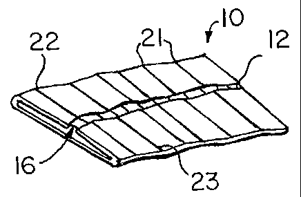
FIGS. 2 and 3 are views of the paperband having transverse undulations or
corrugations 21 to create respective ridges or hills 22 and grooves or valleys
23 to create a
corrugated structure of the band 10.
FIG. 4 illustrates a prior art track assembly 24 having a paperband carrier 25
formed
with a channel 28, two side guide shoulders 27 in grooves 26.
F1G. 5 is a side diagrammatic view of paperband 10, 31 or 38 wound in a roll
29
around center core 30.
FIG. 6 illustrates a second embodiment of the paperband 31 having partially
overlapping side portions 32, 33 defined by longitudinal score lines 34, 35
and edges 37.
The section of the paperband 31 between the side portions 32A, 33A do not
overlap, form
longitudinal lines or narrow areas of weakness 36 since the edge portions are
two layers of
the multi-ply material which the center portion has three layers of the
material and permit
bending along 36 of the paperband 31 during turn-up or other uses.
In FIG. 7, a third embodiment of a paperband 38 includes side portions 39 and
40
and a medial or center portion 45 folded to form a generally S-shape. The side
portion 39
is folded about longitudinal score line 43 forming a "soft bend" 41. The other
side portion
40 is similarly folded about longitudinal score line 44 to form a "soft bend"
42. Areas of
weakness or flexible joints 48 and 49 are created during the transition from
three layers to
CA 02604194 2007-10-09
WO 2006/132731 PCT/US2006/016782
6
two layers. Adhesive layers 46 and 47 are shown on opposed surfaces of the
paperband
38, i.e., an upper surface of side portion 39 and a lower surface of side
portion 40.
Alternately, the adhesive 46, 47 may be applied simultaneously to both
surfaces of center
portion 45. This method may be accomplished by feeding the unfolded paperband
board
vertically to permit the adhesive 46, 47 to be sprayed on or otherwise applied
to center
portion 45 by any appropriate technology.
The performance of paperband 38 is similar to that of paperbands 10, 31 in
track
pullout by way of flexing at joints 48 and 49. After pressing to fix the
adhesive 46, 47, the
desired transverse undulations are formed as in the other embodiments
previously
described. The soft bends 41 and 42 are formed in the manner described to
provide the
paperband 38 with substantially planar outer surfaces as the ends 50, 51
transition more
smoothly with adjacent portions of soft bends 41, 42 to create relatively flat
sides for the
paperband 38 (FIG. 8). In other words, the three-layer center portion of the
multi-ply board
are compressed by uniformly spaced apart rollers and the two-layer edge
portions are
compressed at the same time but only to the thickness determined by the three-
layer center
portion. In addition, the soft bends 41, 42 also increase tear resistance in
the transverse or
crosswise direction of the paperband.
The preferred paperbands 31 and 38 provide for the use of thinner multi-ply
board
(for the same bulk) than other embodiments. This derives from the higher
strength/density
of the thinner board. The horizontal and vertical symmetry of the completed
band is also
preferred. The folded edge portions provide for the "flexing" or bending
during turn-up and
also provide for high resistance to cross-wise tearing of the band and reduced
fiber damage
during compression-forming of the band. The thinner board also allows for more
footage at
the same diameter thus providing for fewer splices of the band.
The undulating or wave-like formations of the paperbands are defined in terms
of
parameters including height, width and number per unit elongate length and are
the result
of the use of rollers or any other appropriate apparatus. The creation of the
corrugations or
undulations 21 causes a selectable shortening of the paperband 10 that
provides a shock
absorbing capability when tensile force is applied to the paperband 10 when it
is stripped
out of track assembly 24 during tum-up or when being pulled tightly during a
baling
operation.
In baling pulp it is common for the bale to "grow" or become enlarged as it
absorbs
moisture from its surroundings. An additional benefit of the corrugations of
the band is that
it allows for growing of the bale without considerably affecting the overall
strength of the
CA 02604194 2007-10-09
WO 2006/132731 PCT/US2006/016782
7
band under the circumstances. The size, shape and number of the corrugations
can be
varied to adjust the stretchability and/or stiffness of the band as desired in
a specific
application.
The preferred methodology of forming the paperband 10 is as follows:
A. The score or crease lines 15 are formed.
B. Adhesive is applied to the center portion 14 between the scores 15 (not
preferred
adhesive applied to side portions 13).
C. The side portions 13 are folded over by a forming die.
D. The side portions 13 are then pressed onto the medial portions 14 to fix
the
adhesive.
E. Transverse corrugations 21 are formed in the paperband.
The specific type of formations 22, 23 and how they are formed varies in the
circumstances. It is important, however, to avoid scores or cuts or similar
formations that
result in a reduction of the tensile strength of the paperband as such result
would be
counterproductive. Transverse indentations which do not materially affect the
strength of
the paperbands in accord with the present invention may be employed to create
undulations where dictated by the specific application.
As the undulations are more pronounced by pressure of the rollers, the height
of the
undulations are increased and/or may be less pronounced by decrease in roller
pressure.
Alternately, the width of undulations and/or the number per lineal distance
may be varied to
increase or decrease the stiffness and/or stretchability of the paperband. In
addition, the
folded edges of the paperbands 10, 31, 38 minimize cross tearing of the
paperbands 10,
31, 38. Preferably, all plies are made of cellulose fibers although other
material may be
used if necessary. Also, all adhesive, which may include PVA, is water-soluble
to aid iri
repulping of the paperband particularly in baling applications. Preferably, if
PVA is used,
the adhesive is applied to both sides of the paperband because the adhesive
sticks best to
itself. The use of PVA on only one side results in inadequate adhesion in many
circumstances.