Note: Descriptions are shown in the official language in which they were submitted.
CA 02604277 2007-09-26
Immersion Lance for Analysis of Melts and Liquids
The invention relates to an immersion sensor for analysis of liquids or melts
with an immersion
carrier comprising a sample chamber with an inlet opening arranged in the
immersion carrier.
Prior Art
Immersion sensors are already known in various configurations. Thus, WO
03/081287 A2 de-
scribes a carrier tube, which is immersed in an aluminum melt. A lens system
is arranged inside
the carrier tube. At the upper end of the tube there is an optical fiber,
which is connected to a
spectrograph on one side and to a laser on the other side via an optical
system. The radiation
emitted by the melt is guided via the optical fiber into the spectrograph;
there the radiation is
analyzed, in order to derive therefrom analysis results on the composition of
the aluminum melt.
DE 103 59 447 Al likewise describes an immersion sensor for analysis of molten
metals with an
immersion carrier, with a detector, and also with a radiation-guiding device
for receiving and
transmitting radiation and with a signal interface arranged on or in the
immersion carrier. Here,
the signal interface is connected to the detector.
Object of the Invention
CA 02604277 2007-09-26
2
An object of the present invention is to improve existing devices, to simplify
handling, and to
allow a more precise analysis of melts and/or liquids.
This object is solved just with the features of the independent claim.
Advantageous refinements are to be taken from the respective dependent claims.
The immersion sensor according to the invention for analysis of liquids or
melts with an immer-
sion carrier, which has a sample chamber with an inlet opening arranged in the
immersion car-
rier, provides that the sensor for measuring the melt is arranged in the
sample chamber.
The liquids or mel#s preferably include glass or metal melts, particularly
aluminum or steel melts.
The sensor is directed toward a previously determined point in the sample
chamber. The analy-
sis takes place at this point. The liquid or melt to be analyzed is fed to
this point, so that the free
surface lies in the measurement area of the sensor.
For the analysis an excitation of the liquid or melt can occur. Here, for
example, a beam is gen-
erated by a beam-generating unit and directed toward the previously determined
point in the
sample chamber. For the beam a laser beam can be used, but instead other beam
types are
definitely conceivable. The beam generates particles and/or radiation at the
defined measure-
ment point, which are emitted and guided to a collection device. For the
collection device can be
used, in particular, a detector, a radiation converter, a spectrometer, an X-
ray spectrometer or
mass spectrometer. The measurement can be performed optically, for example as
a tempera-
ture measurement, or for determining the chemical composition, for example by
LIBS (laser-
induced breakdown spectroscopy).
CA 02604277 2007-09-26
3
An analysis in a sample chamber leads to particularly precise measurement
results, since in the
region of the measurement point, a gas atmosphere suitable for the analysis
can be produced
without thereby changing the position of the measurement point.
With an analysis inside the sample chamber, waves and movements of the melt
which falsify
the measurement result, are also avoided. The analysis on the flowing liquid
or melt reduces
any influences by the measurement itself, e.g., an enrichment or depletion of
individual ele-
ments by the excitation, and produces a better accuracy of the analysis than
when the same
sample volume is always used, or when the composition of the melt is changed
by the meas-
urement itself.
Here, analysis will be understood to be the measurement, that is, the
determination of a value
through quantitative comparison of the measurement parameter with a scale,
particularly of che-
mical or physical values.
An immersion sensor according to the invention allows analyses and
measurements of the melt
at different points in the melt, since a change of position of the sensor can
be easily carried out.
Advantageously, the sensor is directed toward a predefined measurement point
inside the sam-
ple chamber, at which the freshly inlet melt or liquid is guided past. This
guarantees a defined
distance between the sensor and the melt surface. This leads to particularly
precise and compa-
rable results.
An advantageous embodiment of the invention provides that the predefined
measurement point
lies at an inlet opening of the melt into the sample chamber. It has been
shown that a precise
measurement of the composition of the melt is thereby possible, because fresh
melt is con-
stantly supplied and only a very minimal cooling of the melt occurs. The
accuracy is improved,
CA 02604277 2007-09-26
4
and at the same time a change in the composition of the melt by the analysis
is prevented, be-
cause fresh melt is always supplied.
Advantageously, the measurement point is arranged at or on an analysis plate.
The analysis
plate likewise allows a defined distance between the sensor and melt. The
analysis plate also
results in the flow rate of the melt being reduced and the surface of the melt
being increased,
and thus a more precise analysis can occur.
Advantageously, the inlet opening is an inlet tube. It has been shown that an
inlet tube can en-
sure that during the predominant period of the analysis only a pure melt is
supplied to the
measurement point. Slag and other deposits that falsify the analysis result
are prevented. The
inlet tube can also be shaped such that the inlet flow rate of the melt is
reduced. Thus, the inlet
flow rate can be controlled, for example by a bending or narrowing of the
inlet tube.
The melt is collected in the sample chamber beneath the measurement point.
Advantageously, the immersion sensor has a melt level detector. This melt
level detector meas-
ures the level of the melt in the sample chamber and allows the sensor to be
pulled from the
melt when the sample chamber is filled with melt up to a defined level. Damage
to the sensor
and the optics contained in the sensor can thereby be prevented. Such melt
level detectors can
include contact probes, ultrasound sensors, optical sensors, or the like.
Here, all other devices
are conceivable, which allow a measurement of the level.
It is definitely conceivable that the level detector is connected to a device,
which allows an au-
tomatic removal of the sensor from the melt at a defined level.
CA 02604277 2007-09-26
Here it is further advantageous if the optics or other sensitive parts are
protected with a protec-
tive window against spray or vapors of the melt.
It is advantageous if the immersion carrier is constructed as a tube. The
individual parts can
thereby be easily arranged in the immersion sensor and are protected during
transport.
Advantageously, the detector has a device for receiving radiation and for
converting it into elec-
trical signals. In particular, the detector is designed for receiving and
converting visible light,
ultraviolet radiation, infrared radiation, X-ray radiation, and/or microwave
radiation into electrical
signals. Consequently, all types of optical or other radiation can be received
and used for ana-
lyzing the melt.
It is advantageous if an optical spectrometer, an X-ray spectrometer, and/or a
mass spectrome-
ter is arranged on or in the immersion carrier.
An advantageous construction of the invention provides that the immersion
sensor has a modu-
lar design, preferably in two parts. In this way, a part, advantageously the
upper part, is a reus-
able part, which contains the devices for analysis. The lower part is designed
for one-time use
and contains the sample chamber. The upper, reusable part can remain
completely above the
melt during the analysis process.
In order to protect the -immersion sensor from the heat, it is advantageous if
the immersion sen-
sor is water-cooled. Longer analysis times are thereby allowed, which leads to
more precise
analysis results.
It is advantageous if the immersion sensor has a protective cap, which is
located at the inlet
opening and which melts away only after a certain period after immersion. In
this way it can be
CA 02604277 2007-09-26
6
ensured that only clean melts, that is no slag, reach the measurement point,
and a precise
measurement and analysis are allowed.
The invention is explained in more detail below using preferred embodiments
and with refer-
ence to the enclosed figures.
Shown here in schematic representation are:
Figure 1 cross section through an immersion sensor according to the invention
Figure 2 view of the sample chamber with measurement point
Figure 3 representations of the measurement plate
Figure 4 another view of the sample chamber with measurement point
Figure 5 device for measurement and analysis of melts
Figure 6 another view of the sample chamber with measurement point.
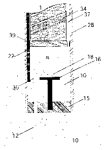
Figure 1 shows an immersion sensor 1 according to the invention in cross
section. The immer-
sion sensor 1 is surrounded by a protective tube 28. At the lower end of the
immersion sensor 1
the sample chamber 17 is located. Inside the sample chamber 17 there is a melt
level detector
22, a sample plate 16, and an inlet opening 14, which is formed in this case
by an inlet tube 36.
The end of the inlet tube 36 facing the melt 10 is provided with a protective
cap 12, which melts
away after the immersion sensor 1 is immersed in the melt 10 and thus ensures
that only clean
melt 10 reaches the measurement point 18. Upon immersion of the immersion
sensor 1 into the
melt 10, the protective cap 12 dissolves and the melt 10 enters the sample
chamber 17 through
the inlet opening 14. When the melt 10 enters the sample chamber 17, the melt
10 is analyzed
at a defined measurement point 18. The measurement point 18 is arranged in
Figure 1 on a
sample plate 16. Here, the sample plate 16 can be arranged at any desired
position inside the
sample chamber 17. The melt 10, which enters through the inlet opening 14 into
the sample
CA 02604277 2007-09-26
7
chamber 17, is collected on the floor of the sample chamber 17. If necessary,
this can also be
removed when the immersion sensor 1 is removed and used for additional
analyses. In the up-
per part of the immersion sensor 1 are located the optics 34 and also a gas
conduit 37 for sup-
plying gas, in order to allow a certain pressure inside the sample chamber 17.
Figure 2 shows the view of the sample chamber 17 with measurement point 18.
Here, the
measurement point 18 is not arranged on a sample plate 16, but instead the
measurement of
the melt 10 occurs at its entry from the inlet opening 14 into the sample
chamber 17. The entry
of the melt 10 occurs through an inlet tube 36.
Figure 3 shows various constructions of the inlet tube 36. In Figure 3a the
inlet tube 36 is
formed such that the melt 10 must flow through an arc 30. Here, the inlet tube
36 has at its end
located in the sample chamber 17 a region which is milled off at the top. In
this region the melt
can be analyzed particularly well, because this region forms a sort of sample
plate 16.
Figure 3b shows another construction of the inlet tube 36. Here, the inlet
tube 36 has an arc 30,
which should prevent the melt 10 from flowing too quickly into the sample
chamber 17. The up-
per region of the inlet tube 36 is formed as the sampleplate 16. The melt 10
flows over the
edge of the sample plate 16 and thus reaches the sample chamber 17. The
measurement of the
melt 10 can occur either on the sample plate 16 or upon overflowing of the
melt 10 past the
edge of the sample plate 16.
In Figure 3c another possibility is shown for how the melt 10 can be analyzed.
The melt 10 rea-
ches the sample chamber 17 via an inlet tube 36 and there flows onto a sample
plate 16. The
sample plate 16 has an overflow channel 32, at which the controlled discharge
of the melt 10
occurs.
CA 02604277 2007-09-26
8
If necessary, the sample plate 16 can be flat, high-crowned at the outside or
high-crowned in
the middle, or can have a complicated shape and special features, as for
example the overflow
channel 32. Here, the inlet tube 36 and sample plate 16 can be separate
components or can be
integrated monolithically into the sample chamber 17. In order to minimize
contamination of the
melt 10 before the analysis, pure quartz glass can be used as the inlet tube
36. Instead, ce-
ment, ceramics, or similar materials are here also conceivable as the inlet
tube 36 and sample
plate 16.
Figure 4 shows another view of the sample chamber 17 with measurement point
18. Here, the
melt 10 is introduced into the sample chamber 17 via an inlet tube 36, which
is located at the
side of the immersion sensor 1. The measurement occurs here when the melt 10
comes out of
the inlet tube 36. Here it is conceivable that the melt 10 can also flow onto
a sample plate.
Figure 5 shows a device for measurement and analysis of melts. The immersion
sensor 1
shown here has an upper, reusable part 20 and a lower part. Inside the
immersion sensor 1 is
located a laser 24 and a spectrometer 26. The immersion sensor 1 has a housing
28, which can
be water-cooled. In the lower part of the immersion sensor 1 is located the
inlet opening 14 with
an inlet tube 36, through which the melt 10 comes into the sample chamber 17
when the im-
mersion sensor 1 is immersed into the melt 10. Here, a quartz glass disk 38 is
used as a protec-
tive window 39 for protecting the laser 28 from vapors or heat radiation of
the melt 10.
In Figure 6 another construction of the immersion sensor 1 according to the
invention is shown.
The immersion sensor 1 has here in the sample chamber 17 a plate 38, which
assumes, among
other things, the function of the sample plate 16.
CA 02604277 2007-09-26
9
List of reference symbols
1 Immersion sensor
Melt
12 Protective cap
14 Inlet opening
16 Sample plate
17 Sample chamber
18 Measurement point
Protective tube
22 Melt level detector
24 Laser
26 Spectrometer
28 Housing
Arc
32 Overflow channel
34 Optics
Inlet tube
37 Gas supply
38 Plate
39 Protective window