Note: Descriptions are shown in the official language in which they were submitted.
CA 02604306 2007-09-25
BELT-DRIVEN RACK GEAR POWER SLIDING DOOR
BACKGROUND OF THE INVENTION
1. Field of the Invention
The invention relates to a power sliding door. More particularly, the
invention relates to a power drive mechanism mounted to a hinge member for
opening
and closing a power sliding door of an automotive vehicle.
2. Description of Related Art
In various types of automotive vehicles, including minivans, delivery
vans, and the like, it has become common practice to provide a vehicle body
with
relatively large side openings that are located immediately behind front doors
and
which are opened and closed with a sliding side door. The sliding side door is
typically mounted with upper and lower hinge members to horizontal tracks on
the
vehicle body for guided sliding movement between a closed position flush with
the
vehicle body, closing the side opening, and an open position located outward
of and
alongside the vehicle body rearward of the side opening. The sliding side door
may
be operated manually or with a power operated system to which the present
invention
is directed.
Examples of conventional power operated systems for automatically
opening and closing the sliding side door are described in United States
Patent Nos.
6,481,783; 6,464,287; 6,435,600; 6,256,930; 6,079,767; 5,833,301; 5,644,869;
5,536,061; 5,434,487; 5,203,112; 5,168,666; and 4,612,729. Commonly assigned
U.S. Pat. No. 6,435,600, which is hereby incorporated by reference as if fully
set forth
herein, discloses a power sliding door system for an automotive vehicle 10. A
sliding
door 36 is operated by a power drive mechanism 124 that is mounted to the door
36
and includes a drive motor 200 mounted within the door, a lower drive unit 204
having a rotatable pinion gear 208 mounted to a hinge member 120 fixed to the
door
36, and a flexible driveshaft 202 coupling the drive motor 200 and pinion gear
208 for
transmitting drive torque therebetween. The pinion gear 208 meshingly engages
a
rack 38 mounted along a floor 30 of a vehicle body 14 to open and close the
door 36.
1
CA 02604306 2007-09-25
While the arrangement disclosed in U.S. Pat. No. 6,435,600 provides
certain improvements in the pertinent art, several drawbacks have been noted.
These
drawbacks include, for example: (1) interference between drop glass in the
door 36
and the drive motor 200; (2) excessive labor to install; (3) high drive torque
losses in
the curved flexible driveshaft 202 resulting in high manual efforts; (4) high
cost of the
flexible driveshaft 202 and lower drive unit 204 which includes a gear train
consisting
of bevel gears and ball bearings; and (5) excessive noise from the lower drive
unit
204.
Another type of power sliding door system utilizing a rack 17 and a
pinion gear 23 to effect the movement of a sliding side door 1 is disclosed in
U.S.
Patent No. 4,612,729. This type of arrangement, however, requires considerable
accommodating space and modifications to a vehicle body since a motor 18 and
gear
housing 19 are disposed within a floor of the vehicle body and move along the
rack 17
together with the door 1.
U.S. Pat. No. 5,536,601 discloses another type of power sliding door
system. The system utilizes a power drive mechanism 28 that is mounted to a
sliding
door 22 and extends through a side opening in the door 22. The drive mechanism
28
includes a reversible electric motor 62 that drives a friction whee138 which
is spring
biased to forcibly engage a guide track 401ocated beneath a vehicle floor 14
and
attached to a vehicle body 10. The friction whee138 rides along the guide
track 40 to
open and close the door 22 and additionally guides and stabilizes its sliding
movement. Several drawbacks are associated with this arrangement, such as, the
appearance of the door 22, and the cost, reliability and performance of the
drive
mechanism 28.
Various other types of power sliding door systems utilize a cable,
chain, or belt to open and close the sliding side door. For example, U.S. Pat.
No.
5,168,666 discloses a door drive device which includes a guide rai12 in a
vehicle
body 1 defining a path along which a side door 3 moves. An endless belt 22
extends
around first 17 and second 20 pulleys which are arranged at spaced positions
within
the vehicle body 1. A bracket 23 is provided for connecting a portion of the
endless
2
CA 02604306 2007-09-25
belt 22 to the side door 3 and a reversible electric motor 11 drives the first
pulley 17
thereby moving the side door 3 between opened and closed positions. These
types of
power sliding door systems are complicated, include numerous parts, and
require
considerable accommodating space within a floor of the vehicle body 1 since
the belt
22, first 17 and second 20 pulleys, and motor 11 are all disposed therein.
Consequently, it is desirable to provide a simple, inexpensive, quiet,
compact, and easily installed power door drive system for opening and closing
a
power sliding door of an automotive vehicle.
SUMMARY OF THE INVENTION
According to one aspect of the invention, a power door drive system is
provided for moving a sliding side door on a vehicle body having an aperture
between
an open position wherein the side door substantially clears the aperture and a
closed
position wherein the side door substantially covers the aperture. The power
door
drive system includes a guide track mounted to and extending along the vehicle
body
adjacent the aperture. The guide track includes a channel portion and a rack
portion
which has a plurality of rack teeth disposed therealong. A hinge member has a
first
end adapted for mounting to the side door and a second end. The second end has
a
plurality of guide rollers for rollingly engaging the channel portion of the
guide track.
A power drive mechanism is mounted to the hinge member. The power drive
mechanism includes a reversible motor that is operable for producing a drive
torque, a
pinion gear which has a plurality of drive teeth meshingly engaging the
plurality of
rack teeth, and an endless belt for transferring the drive torque from the
motor to the
pinion gear thereby driving the sliding door between the open and closed
positions.
BRIEF DESCRIPTION OF THE DRAWINGS
Advantages of the present invention will be readily appreciated as the
same becomes better understood by reference to the following detailed
description
when considered in connection with the accompanying drawings wherein:
3
CA 02604306 2007-09-25
Figure 1 is a perspective view of an automotive vehicle equipped with
a power door drive system for opening and closing a sliding side door
according to
the invention;
Figure 2 is a fragmentary, perspective view of an interior passenger
compartment of the vehicle illustrated in Figure 1;
Figure 3 is a fragmentary, perspective view of a floor of the vehicle
illustrated in Figure 1 having a guide track with the sliding side door in an
open
position;
Figure 4 is a fragmentary, top perspective view of a lower mounting
assembly coupled to the guide track;
Figure 5 is a fragmentary, bottom perspective view of the lower
mounting assembly coupled to the guide track;
Figure 6 is a perspective view of the lower mounting assembly
mounted to an interior side of the sliding side door showing a hinge-mounted
power
drive mechanism;
Figure 7 is a perspective view of the hinge-mounted power drive
mechanism with a belt cover removed and a dampener shadow gear exploded away
for purposes of illustration;
Figure 8 is another perspective view similar to that of Figure 7
illustrating the hinge-mounted power drive mechanism; and
Figure 9 is a side view of the hinge-mounted power drive mechanism.
DETAILED DESCRIPTION OF THE PREFERRED EMBODIMENT
Referring to Figures 1 and 2, an automotive vehicle of a minivan type
is generally shown at 10 and includes a vehicle body 12. The body 12 defines
an
interior passenger compartment 14 with a floor 16, and a rear side opening 18
positioned on a left side of the vehicle 10 immediately rearward of a front
side
4
CA 02604306 2007-09-25
opening 20. The front 20 and rear 18 side openings provide access to
respective front
and rear areas of the passenger compartment 14. The front side opening 20 is
opened
and closed by a front door 22 that is mounted in a conventional manner on the
vehicle
body 12 for pivotal movement about a vertical axis at a forward edge of the
door 22.
The rear side opening 18 is substantially larger than the front side opening
20, and is
opened and closed by a sliding side door 24. Although not shown in the
Figures, it
will be understood that the vehicle body 12 may be equipped with a
substantially
identical sliding side door on a right side thereof. Additionally, it will be
appreciated
by those skilled in the art that the teachings of the present invention will
have
applicability to other vehicle types and closure styles.
The rear side opening 18 is defined by an upper edge 26, a lower edge
28, a first body pillar 30, and a second body pillar 32. A lower guide track
34 is
disposed in the floor 16 adjacent the lower edge 28 and extends therealong.
Similarly,
a conventional upper guide track 36 is disposed adjacent the upper edge 26 and
extends therealong. The side door 24 is slidably mounted to the lower guide
track 34
with a lower mounting assembly, generally indicated at 38, and to the upper
guide
track 36 with an upper mounting assembly, generally indicated at 40, for
movement
between an open position and a closed position. In the open position, the side
door 24
substantially clears the rear side opening 18 and is disposed rearward
thereof. In the
closed position, the side door 24 substantially covers the rear side opening
18.
Referring to Figure 3, the lower guide track 34 is shown to curve
inward relative to the passenger compartment 14 of the vehicle body 12 as it
approaches the first body pillar 30. Referring to Figures 4 and 5, the lower
guide
track 34 includes a channel portion 42 and a rack portion 44. The channel
portion 42
includes a vertical guide surface 46, shown in Figure 4, and opposing first 47
and
second 48 horizontal guide surfaces, shown in Figure 5. The rack portion 44
includes
a plurality of horizontal, outward facing rack teeth 50 disposed therealong.
The upper
guide track 36 also is shown to curve inward relative to the passenger
compartment 14
of the vehicle body 12 as it approaches the first body pillar 30, as shown in
Figure 2.
5
CA 02604306 2007-09-25
Referring to Figure 2, the upper mounting assembly 40 is mounted to
an upper forward corner of the side door 24. The upper mounting assembly 40
includes an upper hinge member 52 and an upper guide roller 54. A first end 56
of
the upper hinge member 52 is fixedly secured to an interior side 58 of the
side door
24, and the upper guide roller 54 is rotatably coupled to a second end 60 of
the upper
hinge member 52. The upper guide roller 54 is adapted for rolling engagement
with
the upper guide track 36.
The lower mounting assembly 38 is mounted to a lower forward corner
of the side door 24. The lower mounting assembly 38 includes a lower hinge
member
62 having a first vertical portion 64 and a second horizontal portion 66, as
shown in
Figures 3 and 7. The vertical portion 64 is adapted to be fixedly secured to
the
interior side 58 of the side door 24, as shown in Figure 6. Referring to
Figure 7, the
horizontal portion 66 extends between a proximal end 68 adjacent the vertical
portion
64 and an opposite distal end 70. The lower mounting assembly 38 also includes
first
72 and second 741ateral guide rollers, a vertical guide roller 76, and an
articulating
bracket 78. The articulating bracket 78 is pivotally coupled to the distal end
70 of the
horizontal portion 66 by a pivot pin 80. The articulating bracket 78 is
generally U-
shaped, with each end 82, 84 having a cylindrical aperture (not shown) for
receiving a
vertically extending roller pin 86, each one of which journally supports one
of the first
72 and second 74 horizontal guide rollers. A tongue 88 extends in a
perpendicular
direction downward between ends 82, 84 and includes a cylindrical aperture
(not
shown) for receiving a horizontally extending roller pin 90 which journally
supports
the vertical guide roller 76.
Referring to Figures 4 and 5, the lower mounting assembly 38 is
adapted for cooperation with the lower guide track 34 wherein the vertical
guide roller
76 rollingly engages the vertical guide surface 46, and the first 72 and
second 74
horizontal guide rollers rollingly engage the first 47 and second 48
horizontal guide
surfaces. As such, cooperation between the guide rollers 76, 72, 74 and their
respective guide surfaces 46, 47, 48 ensures proper vertical and horizontal
alignment
of the lower mounting assembly 38 to the rack portion 44 of the lower guide
track 34.
Since the articulating bracket 78 is pivotally coupled to the lower hinge
member 62,
6
CA 02604306 2007-09-25
the guide rollers 76, 72, 74 are capable of traversing the curved length of
the lower
guide track 34.
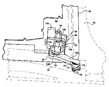
Referring to Figure 6, the side door 24 is shown to include a power
drive mechanism, generally indicated at 92, operatively mounted to the lower
hinge
member 62. In the preferred embodiment, the power drive mechanism 92 includes
a
power unit 94, an endless flexible belt 96, and a drive unit 98, as shown in
Figure 7.
More specifically, the power unit 94 is fixedly secured to the vertical
portion 64 of the
lower hinge member 62 and includes a reversible motor 100, a gearbox 102, and
a
clutch 104.
Referring to Figure 7, an electronic control unit (hereinafter referred to
as an "ECU") 106 for controlling motor speed is mounted adjacent the vertical
portion
64 of the lower hinge member 62. The ECU 106 is coupled electrically to the
motor
100 and clutch 104 by push-in connectors (not shown). A vertically extending
shaft
108 is mounted within an ECU housing 110 for rotatably supporting a first spur
gear
112 and an encoder wheel 114. The first spur gear 112 meshingly engages an
idler
gear 116 driven by the clutch 104 such that rotational movement within the
clutch 104
rotates the idler gear 116, which in turn causes the first spur gear 112 to
rotate.
Rotational movement of the first spur gear 112 causes the shaft 108, and
therefore the
encoder wheel 114 to rotate. An optical sensor 118 mounted to the ECU 106
adjacent
the encoder wheel 114 is adapted to read slots (not shown) in the encoder
wheel 114
as it rotates to determine the position of the side door 24 relative to the
lower guide
track 34 and the velocity at which the side door 24 is traveling.
An output shaft 120 extending axially from the clutch 104 includes a
second spur gear 122 fixed thereto for transmitting drive torque to a third
spur gear
124. The third spur gear 124 is joumally supported by a vertically extending
post 126
mounted to the horizontal portion 66 of the lower hinge member 62 at the
proximal
end 68 thereo~ A toothed drive pulley 128 is also journally supported by the
post 126
below the third spur gear 124 and secured to the third spur gear 124 such that
rotation
of the third spur gear 124 by the second spur gear 122 causes the drive pulley
128 to
7
CA 02604306 2007-09-25
rotate. As seen in Figures 6 and 8, a housing 130 encloses the second 122 and
third
124 spur gears.
Referring to Figure 9, the drive unit 98 includes a toothed driven
pulley 132 rotatably coupled to a vertically extending post 134 mounted to the
horizontal portion 66 of the lower hinge member 62 at the distal end 70
thereof. A
pinion gear 136 is also rotatably coupled to the post 134 above the driven
pulley 132
and secured thereto such that rotation of the driven pulley 132 causes the
pinion gear
136 to rotate. The pinion gear 136 includes a plurality of drive teeth 138
which
meshingly engage the rack teeth 50, as shown in Figure 4. As such, when the
pinion
gear 136 rotates, the side door 24 is moved forward and rearward relative to
the
vehicle body 12. Alternatively, the pinion gear 136 rotates when the side door
24 is
manually moved forward and rearward relative to the vehicle body 12. A
dampener
shadow gear 140, shown in Figures 7 through 9, is secured to an upper surface
142 of
the pinion gear 136, shown in Figure 7, for preventing backlash between the
rack
teeth 50 and the pinion gear 136 when the side door 24 is moved manually,
thereby
preventing rattling. More specifically, the shadow gear 140 includes a
plurality of
teeth 143 which are slightly larger in dimension than the drive teeth 138 of
the pinion
gear 136 such that the shadow gear teeth 143 contact the rack teeth 50 first,
cushioning the impact. The shadow gear teeth 143 compress and the load is then
taken by the drive teeth 138 of the pinion gear 136. It will be appreciated
that the
shadow gear 140 may be formed of a foam or elastomer material, and may be
secured
to the upper surface 142 of the pinion gear 136 by over-molding, an adhesive,
mechanical fasteners, or the like.
The belt 96 can be any suitable belt including rubber belts with Keviar,
steel or other reinforcements and preferably is a reinforced toothed belt
which can
carry relatively large tensile loads and which is not generally subject to
stretching.
Referring to Figure 7, the belt 96 extends around the drive pulley 128 and the
driven
pulley 132 for transferring drive torque therebetween. The length of the belt
96 is
selected to provide a predetermined amount of slack that is taken up by an
idler pulley
144 to set the tension in the belt 96. The idler pulley 144 is journally
supported by a
8
CA 02604306 2007-09-25
vertically extending post 146 mounted to the horizontal portion 66 of the
lower hinge
member 62 between the proximal 68 and dista170 ends.
A belt cover 148 extends between the housing 130 and the distal end
70 of the horizontal portion 66 of the lower hinge member 62 covering the belt
96 and
pinion gear 136, as shown in Figure 6. The belt cover 148 protects the belt 96
from
contact with dirt and grime that typically falls from the shoes of passengers
as they
enter and exit the vehicle 10.
Preferably, the power unit 94, belt 96, and drive unit 98 cooperate to
provide the pinion gear 136 with sufficient drive torque to enable the side
door 24 to
operate while the vehicle 10 is on 20% fore and aft grades with an average
velocity of
approximately 190.5 mm/sec. The clutch 104 is preferably an electromagnetic
clutch
which is operable between a disengaged position wherein the transmission of
drive
torque between the motor 100 and pinion gear 136 is inhibited, and an engaged
position wherein the transmission of drive torque between the motor 100 and
pinion
gear 136 is permitted. Preferably, the clutch 104 is normally maintained in
the
disengaged position which prevents the pinion gear 136 from back-driving the
motor
100 when the side door 24 is manually moved between the open and closed
positions.
Configuration in this manner permits the side door 24 to be opened and closed
manually without substantially increasing the force required to propel the
side door 24
compared to a completely manual side door.
In operation, starting with the side door 24 in the closed position, when
it is desired to move the side door 24 to the open position an electrical
signal is sent to
actuate the clutch 104 from the disengaged position to the engaged position.
The
motor 100 is then actuated to drive in a first direction producing drive
torque which
passes through the gearbox 102 and clutch 104, eventually causing the output
shaft
120 and second spur gear 122 to rotate in a first direction. Rotation of the
second spur
gear 122 in the first direction causes the third spur gear 124 and therefore
the drive
pulley 128 to rotate in a second direction. Engagement between the drive
pulley 128
and the belt 96 causes the belt 96 to rotate in the second direction, whereby
engagement between the belt 96 and driven pulley 132 in turn causes the pinion
gear
9
CA 02604306 2007-09-25
136 to rotate in the second direction. Rotation of the pinion gear 136 in the
second
direction, and the resulting interaction between the drive teeth 138 and rack
teeth 50
moves the side door 24 rearwardly into the open position. At the same time,
rotational movement within the clutch 104 rotates the idler gear 116 which in
turn
causes the first spur gear 112, and thus the encoder wheel 114 to rotate. The
optical
sensor 118 monitors the rotation of the encoder wheel 114 to determine the
position
and velocity of the side door 24.
To close the side door 24 an electrical signal is sent to actuate the
clutch 104 from the disengaged position to the engaged position. The motor 100
is
then actuated to drive in a second direction producing drive torque which
passes
through the gearbox 102 and clutch 104, eventually causing the output shaft
120 and
second spur gear 122 to rotate in the second direction. Rotation of the second
spur
gear 122 in the second direction causes the third spur gear 124 and therefore
the drive
pulley 128 to rotate in the first direction. Engagement between the drive
pulley 128
and the belt 96 causes the belt 96 to rotate in the first direction, whereby
engagement
between the belt 96 and driven pulley 132 in turn causes the pinion gear 136
to rotate
in the first direction. Rotation of the pinion gear 136 in the first
direction, and the
resulting interaction between the drive teeth 138 and rack teeth 50 moves the
side
door 24 forwardly into the closed position. At the same time, rotational
movement
within the clutch 104 rotates the idler gear 116 which in turn causes the
first spur gear
112, and thus the encoder wheel 114 to rotate. The optical sensor 118 monitors
the
rotation of the encoder wheel 114 to determine the position and velocity of
the side
door 24.
Alternatively, the side door 24 can be moved between the open and
closed positions manually. Again, starting with the side door 24 in the closed
position, when it is desired to move the side door 24 to the open position no
electrical
signal is sent to actuate the clutch 104, which therefore remains in the
disengaged
position. With the clutch 104 in the disengaged position the side door 24 can
be
manually moved rearwardly into the open position. As the side door 24 moves
rearwardly the interaction between the rack teeth 50 and the drive teeth 138
cause the
pinion gear 136 and therefore the driven pulley 132 to rotate in the second
direction.
CA 02604306 2007-09-25
Engagement between the driven pulley 132 and belt 96 causes the belt 96 to
rotate in
the second direction, whereby engagement between the belt 96 and drive pulley
128
in turn causes the third spur gear 124 to rotate in the second direction.
Rotation of the
third spur gear 124 in the second direction causes the second spur gear 122
and output
shaft 120 of the clutch 104 to rotate in the first direction. Rotational
movement within
the clutch 104 rotates the idler gear 116 which in turn causes the first spur
gear 112,
and thus the encoder wheel 114 to rotate. At the same time, the optical sensor
118
monitors the rotation of the encoder wheel 114 to determine the position and
velocity
of the side door 24.
To close the side door 24 manually, again no electrical signal is sent to
actuate the clutch 104, which therefore remains in the disengaged position.
With the
clutch 104 in the disengaged position the side door 24 can be manually moved
forwardly into the closed position. As the side door 24 moves forwardly the
interaction between the rack teeth 50 and the drive teeth 138 cause the pinion
gear
136 and therefore the driven pulley 132 to rotate in the first direction.
Engagement
between the driven pulley 132 and belt 96 causes the belt 96 to rotate in the
first
direction, whereby engagement between the belt 96 and drive pulley 128 in turn
causes the third spur gear 124 to rotate in the first direction. Rotation of
the third spur
gear 124 in the first direction causes the second spur gear 122 and output
shaft 120 of
the clutch 104 to rotate in the second direction. Rotational movement within
the
clutch 104 rotates the idler gear 116 which in turn causes the first spur gear
112, and
thus the encoder wheel 114 to rotate. At the same time, the optical sensor 118
monitors the rotation of the encoder wheel 114 to determine the position and
velocity
of the side door 24.
The invention has been described in an illustrative manner, and it is to
be understood that the terminology, which has been used, is intended to be in
the
nature of words of description rather than of limitation. Many modifications
and
variations of the present invention are possible in light of the above
teachings. It is,
therefore, to be understood that within the scope of the appended claims, the
invention
may be practiced other than as specifically described.
11