Note: Descriptions are shown in the official language in which they were submitted.
CA 02604582 2007-09-27
Pagel-
RA,DIAN1' FLOOR TUBING COLLECTOR AND ORGANIZER
This invention is in the field of devices for aiding in the installation of
radiant floor
conduit runs and more particularly for a guide and collector for radiant floor
conduits.
BACKGROUND
Radiant floor heating is a commonly used method of heating a building.
Although there
are a number of different ways to install radiant floor heating, ideally in
lower levels,
-o basements and garagcs uie radiani iioor is-nistaiied-iight-in the-concrete-
:siab.-flefore-a- -------
concrete slab ia poured, tuns of radiant tubing or pipe (such as PEX ttibing)
are
positioned on the ground surface where the concrete slab will be poured
(typically, tied to
the rebar already set in place to secure the radiant pipe in place while the
concrete slab is
being poured). When the pipe is positioned in place in the floor, the concrete
slab is
poured over the pipe. When the concrete sets, the slab then contains runs of
pipe
extending out of the concrete slab that can be coiuiected to a supply of
heated fluid to
radiantly heat the concrete slab and thereby the space.
Usually a number of different runs of pipe are used in a radiant floor heating
system.
2o Each run consists of a supply portion, which carries heated fluid out into
the slab, and a
return portion, which carries the fluid back out of the slab. A number of
different nins of
pipe can be used to control the amount of heat going to different areas in the
concrete
CA 02604582 2007-09-27
- Page 2 -
slab. For exampfe, to heat a bathroom and a living room with different
amounts, a single
run of pipe can be used to heat the bathroom allowing the temperature of the
bathroom to
be controlled separately from a living room that is heated by a different run
of pipe.
Additionally, the length of a run of pipe is limited because too long of a nul
of pipe can
cause significant friction loss in the pipe causing excess temperature
differentials in the
tvn of pipe and therefore in the room or rooms being heated by the run of
pipe. Rooms
that are too large to heat with a single run of pipe ttse two or more runs of
pipe to heat the
space.
io This means that there are typically a number of runs of pipe used in a
concrete slab to
radiantly heat a space. The exact number of different runs that are used will
vary based
on the size of the area to be heated as well as the how much control over the
system is
desired. Each run of pipe starts and ends at a location where a manifold will
be installed.
When the runs of pipe are positioned in place where the concrete slab will be
poured. the
starts =and ends of the runs will have to be bent from vertical (running to
the place where
the manifold will be installed) to horizontal (the direction they will be
ruiming in, in the
concrete slab). To do this the pipe or tubing u.sed for the runs of pipe ntust
be bent up to
change its direction 90 , leaving the ends of the pipe sticking up so that
when the
concrete slab is poured, these ends are left sticking out of the concrete slab
and can
eventually be connected to a manifold.
CA 02604582 2007-09-27
-Page3-
The problem with this installation method is that the pipe or tubing used can
only be bent
to a mrtain angle. Bending it at too great an angle will cause it to kink in
the pipe and
tubing which can impede the flow of fluid through the pipe or tubing. If an
installer
bends it too much, the pipe will be damaged. However, the pipe must change
direc,~tion
from running venically to running horizontally at the location where the
tubing will be
coimecaed tu Llie manlfolci-. Tisis presen[s a Ctraiienge'to'in:staliers.
Presen[iy, most
installers jury-rig a system of trying to hold the ends of the pipe in
location or use various
guides, etc.
t0
SUMMARY OF THE INVENTION
It is an object of the present invention to provide a device that addresses
problems in the
prior art.
In an aspect, an apparatus is provided for holding conduits for in place. The
apparatus
coinprises: a substantially flat bottom edge; a first side; a second side; a
first guide
channel open at the first side of the apparatus and sized to accept a conduit,
the first guide
channel having a length with a first opening at a first end of the first guide
channel and a
second opening at a second end of the fust guide channel, the first guide
channel running
in a first direction at the first opening and transitioning along the length
of the first guide
channel to run in a second direction at the second openiag; and a second guide
channel
CA 02604582 2007-09-27
-Page.4_
open at the first side of the apparatus and sized to accept a conduit, the
second guide
channel having a length with a fu-st opening at a first end of the second
guide channel and
a second opening at a second end of the second guide channel, the second guide
channel
running in a first direction at the first opening and transitioning along the
length of the
second guide channel to run in a second direction at the second opening;
wherein the first
direction is substantially perpendicular to the second direction.
In another aspect, a system for holding a number of runs of conduit in place
is provided.
The system compri.ses: a first apparatus comprising: a substantially flat
bottom edge; a
io first side; a second side; a first guide channel open at the fust side of
the apparatus and
sized to accept a conduit, the first guide channel having a length with a
first opening at a
first end of the first guide channel and a second opening at a second end of
the first guide
channel, the first guide channel running in a first direction at the first
opening and
transitioning along the length of the fint guide channel to run in a second
direction at the
second opening; and a second guide channel open at the first side of the
apparatus and
sized to accept a conduit, the second guide channel having a length with a
first opening at
a first end of the second guide channel and a second opening at a second end
of the
second guide channel, the-second. guide_channel running in a first directinn-
at.-the-first _-_-
_ ---
opening and transitioning along the length of the second guide channel to run
in a second
direction at the second opening; wherein the first direction is substantially
perpendicular
to the second direction and wherein the first side is connectable to an other
apparatus; at
least one additional apparatus comprising: a substantially flat bottom edge; a
first side; a
CA 02604582 2007-09-27
-Page5-
second side; a first guide channel open at the first side of the apparatus and
sized to
accept a conduit, the first guide chaiinel having a length with a first
opening at a first end
of the first guide channel and a second opening at a second end of the first
guide channel,
the first guide channel running in a first direction at the first opening and
transitioning
along the length of the first guide channel to run in a second direction at
the second
opening; and a second guide channel open at the fitst side of the apparatus
and sized to
accept a conduit, the second guide channel having a length with a first
opening at a first
end of the second guide channel and a second opening at a second end of the
second
guide channel, the second guide channel running in a first direction at the
first opening
aiid transitioning along the length of the second guide channel to run in a
second
direction at the second opening; wherein the first direction is substantially
perpendicular
to the second direction and wherein the first side is connectable to an other
apparatus; and
a cover plate connectable to the first side of an additional apparatus such
that the first
guide channel and second guide channel of tlte additional apparatus are
covered by the
cover plate. The first side of the first apparatus is connected to the second
side one of the
at least one additional apparatus and each additional apparatus is comiected
to a previous
one of the at least one additional apparatus and wherein a last additional
apparatus is
coniiected on the first side to the cover plate.
In another aspect a method of holding a plurality of runs of conduit in place
is provided.
The method comprises: providing an apparatm5 a substantially flat bottom edgc;
a first
side; a second side; a first guide channel open at the tirst side of the
apparatus and sized
CA 02604582 2007-09-27
-Pape6-
to accept a conduit, the first guide channel having a length witti a first
opening at a first
end of the fust guide channel and a second opening at a second eud of the
first guide
channel, the first guide channel ninning in a first direction at the first
opening and
transitioning along the iength of the first guide channel to run in a second
directioa at the
second opening; and a second guide channel open at the first side of the
apparatus and
sized to accept a conduit, the second guide channeI having a tength witli a
first opening at
a first end of the second guide channel and a second opening at a second end
of the
second guide channel, the second guide channel running in a first direction at
the first
opening aiid transitioning along the length of the second guide channel to run
in a second
to direction at the second opening; wherein the fust direction is
substantially perpendicular
to the second direction and wherein the _fi_rst sidP is r_nnnPrtahla tn -in
nther appargtirc, fnr
each run of conduit; for each run of conduit, inserting a supply run portion
of the conduit
in one of the first guide channel and the second guide channel of one of the
apparatus and
a return run portion of the conduit in the other of the first guide channel
and the second
- guide channel of the one of the apparatus; and connecting the each of the
apparatuses
together.
A collector comprising a first guide channel and a second guide channel is
provided. The
collector aids in the installation of a radiant heating system by holding the
ends of runs of
radiant floor pipe or tubing (such as PEX pipe) in pl.ace while a concrete
slab is poured
over the nuis of pipe. An installer inserts a first end of a run of pipe in
one of the fErst
channel guide or the second channel guide, places the rnn or pipe where it is
desired in
CA 02604582 2007-09-27
-Page7-
the floor for heating, and then inserts the other end of the run of pipe in
the other of the
first channel guide or second chaimel guide.
The collector changes the direction of the pipe inserted in the collector so
that its
direction changes from running horizontally along a ground surface to being
oriented
vertically, so that the ends of the runs of pipe end up oriented vertically,
so that thcy can
be connected to a manifold that will be located above the slab. The guide
channels
change direction gradually enough, so that pipe or tubing inserted in the
guide channels
will not be damaged by the bend fortzied in the pipe by tlte gitide chanls. -
In a further aspect, the first guide channel and second guide channel are
positioned so that
pipe exiting the top of the connector is spaced substantially the same
distance apart that it
will be connected to a manifold. In a further aspect, a specific width of the
connectors
are used to so that pipe in the collectors are spaced apart to substantially
match a standard
spacing on a manifold that they will be connected to.
Each collector can be connected to another collector so that an installer can
add as many
riws of pipe or tubing that are required for the installation. With each
additional nui of- ---- -- -
pipe needed, an installer simply takes an additional connector and connects it
to a
previous connector.
CA 02604582 2007-09-27
-Page8-
in an aspect, the collector can enclose and protect the pipe or tubing at the
surface of the
cement slab after the cement slab is poured so that the tubing is protected
from floor
finishing equipment, etc.
DESCRIPTION OF THE DRAWiNGS
While the invention is claimed in the concluding portions hereof, preferred
embodiments
are provided in the accompanying detailed description which may be best
understood in
to conjunction with the accompanying diagrams where like parts in each of the
several
diagrams are labeled with like numbers, and where:
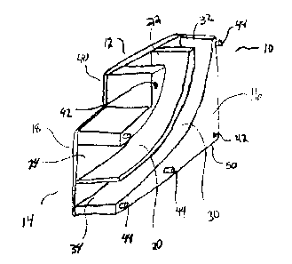
Fig. I is perspective view of a radiant floor conduit collector;
Fig. 2 is a side view of the collector of Fig. 1;
Fig. 3 is a perspective view of two collectors connected together;
Fig. 4 is front view of a collector; and
Fig. 5 is a perspective view of two collectors, connected together, facing in
opposite directions.
CA 02604582 2007-09-27
-Page9-
DETAILED DESCRIPTION OF THE ILLUSTRATED EMBODIMENTS
Fig. 1 illustrates a perspective view of a radiant floor conduit collector 10
for holding
conduits such as radiant floor tubing or piping in place while a cement slab
is poured
around the collector 10. The collector 10 comprises: a top end 12; a bottom
end 14; a
first side 16; a second side 18; a first guide channel 20 having a top opening
22 and a
bottom opening 24; a second guide cbannel 20 having a top opening 32 and a
bottom
opening 34; a number of apertures 42; a number dowels 44; and an end plate 40.
Fig. 2 illustrates a side view of the collector 10. The first guide channel 20
and second
guide channel 30 are positioned in the collector 10 and siaed to fit a desired
size of
conduit. The first guide channel 20 and second guide chaiuiet 30 are open on
the fiist
t5 side 16 of the collector 10 so that conduit can be inserted into the first
guide channel 20
a17C1 tl1e.SCCond !tl!i~1~ ~IL1nnPl 30 tl~nup~2 thN onPni~to {~n the ~r~t
cirlP 1Fi_ T7i~_ firCt en1ir-e_
.._
'
r_-,~-:_- -- -
=_.~.~ -
_.,., ; ._.. ~-_-
-- __-_ --_ ~= -- -- - - - --- --- - --- - - -- -- - -- ----
=-'= - - ..,.. _ _ _..... _.. . -- - - ----
=-___=___. - .:;f = .- - ._.--~,_:- --.~~-_-- . . _ .. _ _ .
CA 02604582 2007-09-27
- Page 10 -
channel 20 defines a curved path that slowly change the orientation of the
first guide
channei 20 from the vertical direction at the top end 12 to the horizontal
direction at the
bottom end 14 at a degree that will not damage a radiant floor conduit
inserted into the
first guide channe120. In one aspect, the curved path follows a constant
radius.
1L L= _~-- _lll 11UV1 (.U' n_'_'-AUUIL ~_.-' l'.clll tVG 1l- =--WC.'~ d 1ntV
rtGU= ~ in the r= lI1 b'UI--Jl ' ---' -LLG l:l!L-[L11C11---lti llJ
I13al1riG'i, a lAUlQ ~11Q1:C I1
20 through the open end on the first side 16 and the first guide channel 20
will change the
direction of the conduit from a vertical direction at the top end 12 of the
collector 10 (so
that it can be connected to a manifold that supplies heated fluid) to
horizontal at the
bottom end 14 of the collector 10 with a gradual enough bend that the tubing
used for the
conduit will not be damaged.
The second guide channel 30 has a top opening 32 at the top end 12 of the
collector 10
and a bottom opening 34 at the bottom end 14 of the collector 10. The top
opening 32 is
positioned horizontally, so that a conduit passing through the top opening 32
is oriented
in a vertical direction, and the bottom opening 34 is positioned vertically,
so that a
conduit passing tllrough the bottom opening 34 is oriented in a horizontal
direction. Like
the first guide channel 20, the second guide channel 30 defines a curvcd path
that
gradually changes the orientation of the first guide chaiuiel 20 from the
vertic.al direction
at the top opening 32 to the horizontal direction at the bottom opening 34
changing the
direction of the second guide channel 30 gradually enough so as not to damage
a conduit
CA 02604582 2007-09-27
- Yage ! 1 -
-,ns.,.a~-.~d ;irt;.c . rccendgnide elannel 30. In eneaspeEt, the e'rcrved
p8tlÃell6v' ed by the
second guide channel 20 has a constant radius.
An end plate 40 is positioned on the second side 18 of the collector 10 so
that when a
conduit is slid into place in the first guide channel 20 and second guide
channel 30, the
conduit is held in place by the end plate 40. Typically, the end plate 40 is
molded as an
integral piece of the collector 10.
In operation, the collector 10 is used to position the end of a run of conduit
so that it will
extend out of a concrete slab that is poured over the run of conduit to form
part of a
radiant floor heating system. In one aspect, a portion of the top end 12 of
the collector 10
can be left extending above a top surface of a poured concrete slab so that a
conduit
placed in the collector 10 can be completely enclosed at the top end iz to
prevent the
conduit from being damaged by floor fmishing materials or other devices during
construction. A run of conduit is started with a supply portion starting from
a location
where a manifold will be installed. An installer inserts the supply portion of
the conduit
in either the first guide chansiet 20 or the second guide channel 30. At this
point, the
conduit will no longer be oriented downwards, but rather, the collector 10
will have
altered the direction of the conduit so that it is oriented in a horizontal
direction. The
installer can then run the supply portion of the run of conduit out onto the
ground surface
where the cement slab will be poured. The run of conduit is then run back to
the
collector 10 and the location where the manifold will be installed in a return
portion of
CA 02604582 2007-09-27
-Page12-
the run of conduit. Once the run of conduit is back at the collector 10, the
installer inserts
the return portion of the run of conduit in the other of the second guide
channel 30 and
first guide chatmel 20 (the one that was not used to guide the supply portion
of the
conduit). If only a single run of eonduit is being used for the radiant floor
heating
system, a cover plate (not shown) can be place on the side of the collector 10
to keep the
conduit in the fixst. guide channel 20 and the second guide channel 30 while
the cement
slab is being poured.
In one aspect, the top opening 22 of the first guide channel 20 is spaced a
distance D
from the top opening 32 of the second guide channel 30 so that the ends of a
run of
conduit spaced substantially the same distance apart that they will need to be
in order to
connect to a standard spaced manifold that ttie conduits will eventually be
connected to.
A bottom edge 50 of the collector 10 is flat and sized to be wide enough so
that the
collector 10 will siz securely the ground surface 80 and support itself in
place on the
ground surface 80 while the concrete slab is beingpoured aroul-ld th e
collector lv.
Each collector 10 is adapted to be attached to other collectors 10 using a set
of apertures
42 and dowels 44 on the first side 16 and second side 19 of the collector 10.
Fig. 3 illustrates two collectors IOA, IOB attached to each other to hold two
runs of
conduit for a radiant floor heating system. A first collector IOA is
positioned to hold a
CA 02604582 2007-09-27
- Page 13 -
first run of conduit, including a supply portion through either the first
guide channel 20 or
the second guide cliatmel 30 and a return portion, through tlte other of the
first guide
channe120 or second guide chaQViel 30. Once the first run of conduit is
positioned in the
first collector 10A, the second collector 10B is then placed adjacent to the
first side 16 of
the first collector 1 OA and comlected to the first collector l0A by mating
the apertures 42
on the first side 16 of the f-rst collector IOA with the dowels 44 on the
second side 18 of
the second collector 10B and the dowels 44 on the first side 6 of the first
collector l0A
with the apertures 42 on the second side 18 of the second collector 10B. The
second side
18 of the second collector IOB now holds the fint run of conduitin nlace
inythefirst
open tops of the first guide channe120 and the second guide channel 30.
A second run of conduit is then inserted in the second collector IOB and a
cover plate 100
can then be connected to the ftrst side 16 of the second collector lOB, using
the apertures
I 42 and dowels 44 on that first side 16 of the second collector IOB, to hold
the second run
of conduit in place in the first guid'e channel 20 and the second guide
channel 30 of the
second collector lOB. With the first collector IOA and second collector IOB
placed on a
ground surface, holding the end of the two runs of conduit in place, the
cement slab can
be poured, encasing both the conduit runs and the first collector 10A and
second collector
20 10B.
CA 02604582 2007-09-27
- Page 14 -
Although Fig. 3 illustrates two collectors 10A, IOB, any number of collectors
10 can be
connected to accommodate any practical number of conduit runs for the radiant
floor
heating system by siniply adding additional collectors 10. For each additional
run of
conduit used in the radiant floor heating system, an additional collector 10
can simply be
added by connecting it to the previous collector 10, once the ends of a run of
conduit are
positioned in the previous collector 10. Once the ends of each run of conduit
have been
positioned in a collector 10, a cover plate 100 can be connected to the last
connector 10,
to hold ttie tubing run in the last connector 10, while the concrete slab is
poured into
place over the connectors 10.
Fig 4 illustrates a side view of a collector 10. In one aspect, a width, W, of
the collector
10 is used so that the spacing of the collectors 10 when they are connected
together,
substantially match a standard spacing of a manifold, which they will be
connected to.
Fig. 5 illustrates a further aspect where two collectors IOC, lOD are attached
to each
other so that a first collector IOC has the bottom opening 24 of theTrst guide
channel 20_
while the bottom opening 24 of the first guide channel 20 and the bottom
opening 34 of
the second guide channel 30 of the second collector 10D, face in an opposite
direction.
The top opening 22 of the first guide channel 20 and the top opening 32 of the
second
guide channel 32 face in the same direction as the top opening 22 of the first
guide
channe120 and the top opening 32 of the second guide channel 32 of the second
collector
CA 02604582 2007-09-27
- Page 15 -
IOD. In this manner, runs of conduit can be run in opposite directions from
the mauifold
(such as when a manifold will be installed on an interior wall), yet still
connected to the
same manifold.
The foregoing is considered as illustrative only of the principles of the
invention.
Further, since numerous changes and modifications will readily occur to those
skilled in
the art, it is not desired to limit the invention to the exact construction
and operation
shown and described, and accordingly, all such suitable changes or
modifications in
structure or operation which may be resorted to are intended to fall within
the scope of
the claimed invention.