Note: Descriptions are shown in the official language in which they were submitted.
CA 02604706 2010-06-18
31536-7
DETERMINATION OF WHEEL SENSOR POSITION
USING A SINGLE RADIO FREQUENCY DETECTOR
IN AN AUTOMOTIVE REMOTE TIRE MONITOR SYSTEM
BACKGROUND
[0002] 1. Technical Field
The invention relates generally to a remote tire monitoring system. More
particularly, the invention relates to a method and apparatus for determining
wheel
sensor position using a single radio frequency detector.
[0003] 2. Background Information
Systems have been developed to monitor a characteristic such as tire pressure
of a vehicle and to report the characteristic to a receiver at a central
monitoring station
using radio transmissions. A monitor is located at each tire and periodically
takes a
measurement of the tire characteristic. The monitor then transmits the results
of the
measurement in a radio frequency transmission to the central monitoring
station
which produces an alarm or a display in response to the measurement.
[0004] One problem with such systems has been the need to program the location
of the transmitters at the central station. To be fully useful, the tire
characteristic data
is preferably associated with the tire which originated the measurement when
presenting a display or alarm. Each monitor includes identification
information which
can be transmitted with the measurement. The tire monitor is preferably
activated to
produce this information and the information is then conveyed to the central
station
and associated with the position of the tire.
1
CA 02604706 2007-10-12
WO 2006/113385 PCT/US2006/013972
[0005] In the technique of U.S. Patent No. 5,600,301, the tire monitors each
include a reed switch or other magnetic device. A magnet is passed near the
reed
switch, causing the monitor to transmit a radio frequency transmission that
includes
identification data. A service technician repeats this process at each wheel
and then
loads the identification and position information into the central monitoring
station.
Another method provides a printed bar code on each tire monitor which contains
the
identification information and which may be read with a suitable bar code
reader.
[0006] In U.S. Patent No. 5,880,363, an activation signal is provided from the
central controller to a low frequency transmitter at each wheel well. The
transmitter
generates a low frequency signal to activate the tire monitor. The tire
pressure
monitor responds by generating a long wave identification signal and
transmitting that
signal with tire pressure and identification data directly to the control
unit. The long
wave identification signal is used to identify the position of the tire by
distinguishing
this transmission from other transmissions received by the controller.
[0007] U.S. Patent No. 5,883,305 discloses two-way communication of data by
radio signals. A tire pressure monitor is activated by a radio frequency
signal
transmitted by an antenna in the wheel well adjacent the tire. The tire
pressure
monitor transmits a second radio frequency signal which is detected by the
wheel well
antenna. The second signal is demodulated to detect that tire pressure data.
[0008] These previous techniques have been limited in effectiveness. The
magnetic programming technique may be subject to interference and crosstalk,
for
example in a factory where many such tire monitors are being assembled with
tires
and vehicles. The bar code label system requires a label at each tire-which
can be lost
or become dirty or illegible. The apparatus for transmitting a long wave
activation
signal and generating a long wave identification signal therefrom is too
expensive for
some applications. The two-way data communication techniques require
demodulation of the received radio signals at the wheel well and coaxial
cabling back
to the central controller, both of which add to the cost of the system.
[0009] A further limitation of some of these prior techniques is the manual
operation requiring activation by a service technician. A system is desired
which
automatically conveys wheel position data to the receiver. Such a system would
be
2
CA 02604706 2007-10-12
WO 2006/113385 PCT/US2006/013972
particularly useful after any change in tire position, such as tire rotation
or
replacement of a tire.
[0010] U.S. patent number 6,518,876, commonly assigned with the present
application, discloses a system and method in which tire monitors are located
at each
wheel of the vehicle and periodically transmit tire data along with a tire
monitor
identifier. Four small, inexpensive RF detectors are located near each wheel.
Each
RF detector is connected to the central control unit by a power line and a
ground line.
When a tire monitor transmits data by emitting an RF transmission, the RF
detector
that is closest to the transmitter will detect the burst of RF energy. The RF
detector
responds to the RF energy by modulating the power line to the control unit
with the
envelope of the transmitted data. The control unit detects this modulation on
one of
its power lines. Also, the RF receiver of the control unit receives and
demodulates the
data transmitted by the tire monitor. The control unit associates the received
data
with the position indication provided by the modulation on the power line.
When the
positions of the wheels on the vehicle are changed, the control unit can
determine the
new position using the modulated power line in association with the tire
monitor
identifier in the transmitted data.
[0011] While this system has been very successful in application, a system
featuring reduced cost and weight is desired. The cables that must be run from
the
control unit to all four RF detectors add substantially to the cost and weight
of an
installation. Accordingly, there is a need for a system and method which
provide the
operational advantages of the earlier system in a system offering reduced
complexity,
parts count, weight and cost.
BRIEF SUMMARY
[0012] By way of introduction only, a tire monitor for use in conjunction with
a
remote tire monitoring system of a vehicle includes in one embodiment a single
radio
frequency (RF) detector, a receiver and a control unit. The RF detector is
associated
with a plurality of tire monitors to detect RF transmissions. Upon detection,
the RF
detector generates a transmission indication. Apart from the RF detector, the
receiver
is operable to receive tire information from the plurality of tire monitors.
The control
3
CA 02604706 2010-06-18
31536-7
unit is coupled with the RF detector and the receiver and operates to
determine
position of the plurality of tire monitors.
[0013] In other embodiment, a remote tire monitor system for use with a
vehicle having a front side, a rear side, a left side and a right side
includes a single
detector, a receiver and a control unit. The single detector is configured to
position proximate one side of the vehicle. The single detector generates a
transmission indication in response to RF transmissions from at least one of
the
plurality of tire monitors. The receiver is operable to receive the tire
information
and the control unit is coupled with the single detector and the receiver. The
control unit is operable to determine a position of the plurality of tire
monitors
based on the detected transmission indications and the tire information.
[0014] In another embodiment, a tire monitor method for a tire monitor
positioned at a wheel of a vehicle includes detecting RF transmissions from a
plurality of tire monitors and receiving tire data from the plurality of tire
monitors.
The tire monitor method further includes determining positions of the
plurality of
tire monitors based on the detected RF transmissions and the tire data.
According to one aspect of the present invention, there is provided a
remote tire monitor system, comprising: a plurality of tire monitors
associated with
wheels of a vehicle and operable to transmit tire information; a single radio
frequency (RF) detector operable to detect a RF transmission from two or more
tire monitors and produce a detected transmission indication; a central
receiver
operable to receive the tire information independently of the single RF
detector;
and a control unit coupled with the RF detector and the receiver, the control
unit
operable to determine positions of the plurality of tire monitors based on the
detected transmission indication from the single RF detector and the received
tire
information from the receiver; wherein the single RF detector is arranged to
be
remotely coupled to the control unit and is arranged proximate one of a front
tire
set and a back tire set and one of a left tire set and a right tire set;
wherein the
control unit is operable to count the detected transmission indication and
compare
count values of the received detected transmission indication for the
plurality of
tire monitors, and the control unit determines left versus right position and
front
versus rear position for the plurality of tire monitors.
4
CA 02604706 2011-05-10
31536-7
According to another aspect of the present invention, there is provided a
remote tire monitor system for use with a vehicle having a front side, a rear
side, a left side
and a right side, comprising: a plurality of tire monitors associated with
each side of the
vehicle and operable to transmit tire information; a single radio frequency
(RF) detector
positioned proximate one side of the vehicle and configured to operatively
generate a
transmission indication in response to radio frequency (RF) transmissions from
at least
one of the plurality of tire monitors; a central receiver operable to receive
the tire
information independently of the single RF detector; and a control unit
coupled with the
RF detector and the receiver, the control unit operable to determine positions
of the
plurality of tire monitors based on the transmission indication from the
single RF detector
and the tire information from the receiver; wherein the single RF detector is
arranged
remote from the control unit and the central receiver is arranged proximate
the control unit,
and the single RF detector is arranged proximate one of a front tire set and a
back tire set
and one of a left tire set and a right tire set; wherein the control unit is
operable to evaluate
a received signal strength for each transmission from the plurality of tire
monitors and the
control unit is operable to determine front versus rear position information
based on the
detected transmission indication and left versus right position information
based on the
received signal strength.
According to still another aspect of the present invention, there is provided
a
remote tire monitor system for use with a vehicle having a front side, a rear
side, a left side
and a right side, comprising: a plurality of tire monitors associated with
each side of the
vehicle and operable to transmit tire information, each tire monitor including
an
acceleration sensor to detect acceleration values and generating an
acceleration signal for
the acceleration values; a single radio frequency (RF) detector positioned
proximate one
side of the vehicle and operable to generate a transmission indication in
response to radio
frequency (RF) transmissions from at least one of the plurality of tire
monitors; a receiver
operable to receive the tire information; and a control unit coupled with the
RF detector
and the receiver, the control unit operable to determine positions of the
plurality of tire
monitors based on the transmission indication and the tire information, the
control unit also
4a
CA 02604706 2010-06-18
31536-7
operable to evaluate the acceleration signal for each transmission from the
plurality of tire monitors.
According to yet another aspect of the present invention, there is
provided a tire monitor method for use with a vehicle having a front side, a
rear
side, a left side and a right side, the method comprising: positioning a
single radio
frequency (RF) detector proximate one of a front tire set and a back tire set
and
one of a left tire set and a right tire set; at the single RF detector,
detecting RF
transmissions from at least one of a plurality of tire monitors associated
with each
side of the vehicle; at a central receiver, receiving tire data from the
plurality of tire
monitors independently of the detection of the RF transmissions at the single
RF
detector; at a control unit, determining positions of the plurality of tire
monitors
based on the detected RF transmissions from the single RF detector and the
tire
data from the receiver, wherein determining positions comprises: at the
control
unit, counting a number of detected transmissions from each tire monitor; at
the
control unit, comparing the number of detected transmissions among the
plurality
of tire monitors; selecting at least one identifier having a greater number of
the
detected transmissions than the rest of the tire monitors; processing the
received
tire data to extract an identifier of each tire monitor; and associating the
identifier
with the number of detected transmission.
According to a further aspect of the present invention, there is
provided a tire monitor method for use with a vehicle having a front side, a
rear
side, a left side and a right side, the method comprising: at a plurality of
tire
monitors associated with each side of the vehicle, generating acceleration
signals
representing acceleration values that arise from rotation of wheels;
positioning a
single radio frequency (RF) detector proximate one side of the vehicle; at the
single RF detector, detecting RF transmissions from at least one of the
plurality of
tire monitors; at a receiver, receiving tire data from the plurality of tire
monitors;
and at a control unit, determining positions of the plurality of tire monitors
based
on the detected RF transmissions and the tire data by at least evaluating a
polarity
of the acceleration signals and determining a left versus right position of
the tire
monitors based on the polarity of the acceleration.
4b
CA 02604706 2010-06-18
31536-7
According to yet a further aspect of the present invention, there is
provided a tire monitor method for use with a vehicle having a front side, a
rear
side, a left side and a right side, the method comprising: at a plurality of
tire
monitors associated with each side of the vehicle, generating acceleration
signals
representing acceleration values that arise from rotation of wheels;
positioning a
single radio frequency (RF) detector proximate one side of the vehicle; at the
single RF detector, detecting RF transmissions from at least one of the
plurality of
tire monitors; at a receiver, receiving tire data from the plurality of tire
monitors;
and at a control unit, determining positions of the plurality of tire monitors
based
on the detected RF transmissions and the tire data by at least evaluating a
polarity
of the acceleration signals and determining a front versus rear position of
the tire
monitors based on the polarity of the acceleration.
According to still a further aspect of the present invention, there is
provided a tire monitor method for use with a vehicle having a front side, a
rear
side, a left side and a right side, the method comprising: at a plurality of
tire
monitors associated with each side of the vehicle, generating acceleration
signals
representing acceleration values that arise from rotation of wheels;
positioning a
single radio frequency (RF) detector proximate one side of the vehicle; at the
single RF detector, detecting RF transmissions from at least one of the
plurality of
tire monitors; at a receiver, receiving tire data from the plurality of tire
monitors;
and at a control unit, determining positions of the plurality of tire monitors
based
on the detected RF transmissions and the tire data by at least evaluating
lead/lag
relationship of the acceleration signals; and determining a left versus right
position
of the tire monitors, based on the lead/lag relationship of the acceleration.
According to another aspect of the present invention, there is
provided a tire monitor method for use with a vehicle having a front side, a
rear
side, a left side and 'a right side, the method comprising: at a plurality of
tire
monitors associated with each side of the vehicle, generating acceleration
signals
representing acceleration values that arise from rotation of wheels;
positioning a
single radio frequency (RF) detector proximate one side of the vehicle; at the
single RF detector, detecting RF transmissions from at least one of the
plurality of
tire monitors; at a receiver, receiving tire data from the plurality of tire
monitors;
4c
CA 02604706 2010-06-18
31536-7
and at a control unit, determining positions of the plurality of tire monitors
based
on the detected RF transmissions and the tire data by at least evaluating
lead/lag
relationship of the acceleration signals and determining a front versus rear
position of the tire monitors based on the lead/lag relationship of the
acceleration.
[0015] The foregoing discussion of the preferred embodiments has been
provided only by way of introduction. Nothing in this section should be taken
as a
limitation on the following claims, which define the scope of the invention.
BRIEF DESCRIPTION OF THE DRAWINGS
[0016] FIG. 1 is a block diagram of one embodiment of a remote tire
monitor system shown in conjunction with portions of a vehicle;
[0017] FIG. 2 is a flow diagram illustrating one embodiment of an auto learn
method for the remote tire monitor system of FIG. 1;
[0018] FIG. 3 is a flow diagram illustrating one embodiment of an auto learn
method for the remote tire monitor system of FIG. 1;
[0019] FIG. 4 is a block diagram of a vehicle with a remote tire monitor
system using two RF (Radio Frequency) detectors;
[0020] FIGS. 5 and 6 and are a flow diagram illustrating one embodiment of
a remote tire monitor system;
4d
CA 02604706 2010-06-18
31536-7
[0021] FIG. 7 is a block diagram of a vehicle with a remote tire monitor
system
using a single front RF detector;
[0022] FIG. 8 is a flowchart illustrating a first example operation of the
remote
tire monitor system using the front RF detector;
[0023] FIG. 9 is a flowchart illustrating a second example operation of the
remote
tire monitor system using the front RF detector; and
[0024] FIG. 10 is a flowchart illustrating a third example operation of the
remote
tire monitor system using the front RF detector.
DETAILED DESCRIPTION OF THE DRAWINGS AND THE PRESENTLY
PREFERRED EMBODIMENTS
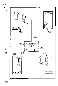
100251 Referring now to the drawing, it is a block diagram of a remote tire
monitor system 100 shown in conjunction with portions of a vehicle 102. The
vehicle
102 includes in this example four tires 104. Other numbers of tires may be
included,
such as a fifth tire as spare or additional tires if the vehicle is a truck,
trailer or other
multi-wheeled vehicle.
[0026] Associated with each of the tires 104 is a transmitter or tire monitor
106.
Each of the tire monitors 106 includes a battery powered, radio frequency (RF)
transmitter. Any suitable tire monitor may be used. U.S. Patent Application
serial
number 09/245,938, entitled "Method And Apparatus For A Remote Tire Pressure
Monitor System," filed February 5, 1999 in the name of McClelland et ah, and
commonly assigned with the present application
illustrates one suitable tire monitor for use in the remote tire pressure
monitor
system 100. Each tire monitor 106 includes a sensor such as a pressure sensor
for
measuring a tire characteristic. The tire monitor 106 converts the measured
tire
characteristic to tire data. The tire data is encoded for transmission from
the tire
monitor 106.
[0027] The tire monitor further includes a transmitter configured to transmit
RF
signals including the tire data. In some embodiments, the transmissions are
encoded
or randomized to minimize clashes at a receiver. For example, U.S. Patent
Application serial number 09/245,577, entitled "Method For Communicating Data
In
A Remote Tire Pressure Monitoring System," filed February 5, 1999 in the name
of
5
CA 02604706 2010-06-18
31536-7
Bailie, et al., and commonly assigned with the present application.
This application shows a technique in which data words are
transmitted separated by a time delay. The time delay for each respective data
word is
defined according to a repeating pattern common to the tires so that data
words are
transmitted during a plurality of aperiodic time windows. Transmission
parameters
such as modulation techniques, transmission frequency and transmission power
are
chosen according to local regulations and to assure reliable reception of the
RF
signals.
[0028] The tire monitor 106 includes a motion switch 139. The motion switch
139 closes upon detection of movement of the vehicle 100. The motion switch
139
provides a signal to the processor 124 indicating closure of the switch 139
and motion
of the vehicle. In response to closure of the switch, the tire monitor system
100
begins operating, for example, by transmitting tire data. In the illustrated
embodiment, during normal operation, the tire monitor 106 transmits
supervisory tire
pressure information once every minute. Any suitable motion switch may be used
for
the switch 139.
[0029] The remote tire monitor system 100 includes a control unit 110 and a
plurality of radio frequency (RF) detectors 112. In alternative embodiment,
the
remote tire monitor system 100 additionally includes a user display for
providing user
information such as tire pressure information and low tire pressure alarms. In
the
illustrated embodiment, each RF detector 112 is mounted on the vehicle 102
proximate an associated tire monitor 106 to detect the RF signals from the
associated
tire monitor 106 and produce a transmission indication in response to detected
RF
signals. Each of the RF detectors 112 is electrically coupled by a conductor
114 to
the control unit 11g. Structure and operation of the RF detectors 112 will be
described in greater detail below.
[0030] The control unit 110 includes an RF receiver 120, an RF decoder 122,
and
a controller 124. The RF receiver 120 is configured to receive RF signals
conveying
tire data from at least one transmitting tire monitor 106 of the plurality of
tire
monitors 106 associated with the wheels or tires 104 of the vehicle 102. Any
suitable
RF receiver circuit may be used. The design and implementation of the RF
receiver
120 will depend on the type of modulation used for the RF signals,
transmission
6
CA 02604706 2007-10-12
WO 2006/113385 PCT/US2006/013972
frequency for the RF signals, and physical limitations such as permitted size,
weight
and power dissipation.
[00311 The RF decoder 122 is configured to receive a transmission indication
from at least one receiving RF detector 112 of a plurality of RF detectors 112
associated with wheels or tires 104 of the vehicle 102. Thus, a tire monitor
106 will
transmit RF signals which are detected by the RF detector 112 associated with
the
transmitting tire monitor 106. The receiving RF detector 1 12 signals its
detection of
the RF signals by providing the transmission indication on its associated
conductor
114.
[0032] The RF decoder 122 is further configured to identify a position of a
transmitting tire monitor on the vehicle in response to the transmission
indication
received from an RF detector. Accordingly, the RF decoder 122 includes a
plurality
of input circuits 123 coupled to the conductors 114 which are in turn coupled
to the
RF detectors 112. A transmission indication impressed on a conductor 114 is
detected
by an associated input circuit 123. In the illustrated embodiment, there is a
one-to-
one relationship between input circuits 123 and RF detectors 112. In this
manner, the
RF detector 112 which originated the transmission indication may be identified
by the
RF decoder determining which input circuit 123 detects the transmission
indication.
In alternative embodiments, the RF decoder 122 may include fewer than four
input
circuits 123 which are multiplexed in some manner among the plurality of RF
detectors 112. For example, a single input circuit 123 may be time shared
among the
plurality of RF detectors 112 to reduce the cost and complexity of the RF
decoder
122.
[0033] The RF decoder 122 is electrically coupled with the RF circuit 120.
Upon
receipt of RF signals at the RF circuit 120, the RF signals are demodulated to
extract
the tire data contained within the RF signals. In some applications,
additional data
decoding may be required after demodulation. The tire-data in one exemplary
embodiment includes a tire monitor identifier, or unique identification code
which
uniquely identifies the tire monitor 106 which transmitted the RF signals. In
addition,
in this exemplary embodiment, the tire data also includes tire pressure data
related to
a sensed tire pressure of the tire 104 at which the transmitting tire monitor
106 is
7
CA 02604706 2007-10-12
WO 2006/113385 PCT/US2006/013972
located. Alternative tire data may be included or substituted for the tire
pressure data,
such as a number of tire revolutions, tire temperature, and so forth.
[00341 After extracting the tire data from the RF signals, the tire data is
conveyed
from the RF receiver 120 to the RF decoder 122. The RF decoder 122 associates
the
tire data with a position of the transmitting tire monitor 106 on the vehicle
102.
Position information is determined using the input circuit 123 and a
transmission
indication received over a conductor 114 from RF detector 112. The tire data
and
associated tire position are conveyed from the RF decoder 122 to the
controller 124.
[0035] The controller 124 controls the operation of the remote tire monitor
system
100. The controller 124 is preferably a microcontroller including a processor
128 and
a memory 126. The processor 128 operates in response to data and instructions
stored
in the memory 126 to control overall operation of the system 100.
[00361 In the illustrated embodiment, the processor 128 stores position data
for a
plurality of tire monitors 106 of the remote tire monitor system 100. The
controller
124 is electrically coupled to the RF decoder 122 to receive tire data and
position data
from the RF decoder 122. In the illustrated embodiment, when tire data and
position
data are received at the microcontroller 124, the processor 128 retrieves
stored
position data from the memory 126. In one embodiment, the position data are
stored
in association with a position on the vehicle, such as left front, left rear,
right front or
right rear. The received position data is compared with the stored position
data. If
there is no change, the position data is not updated and further processing
may occur
using the received tire data. However, the processor 128 updates the position
data for
the transmitting tire monitor 106 when the position of the transmitting tire
monitor
106 varies from the stored position data for the transmitting tire monitor.
Thus, the
controller 124 includes a memory 126 and a processor configured to store in
the
memory 126 position of the plurality of tire monitors 106 including the
position of the
transmitting tire monitor which originated the received position data.
[00371 In an alternative embodiment, the memory 126 is not used for storage of
position data. Rather, the received tire data is associated by the control
unit 110 with
the position information provided by the transmission indication from a RF
detector
112. The tire data and the position information from the input circuit 123 are
used
together to produce a display or alarm, if appropriate, by the system 100.
8
CA 02604706 2007-10-12
WO 2006/113385 PCT/US2006/013972
Additionally, in still another embodiment, the tire data omits any identifying
information for the transmitting tire monitor 106 and again, the tire data and
the
position information from the input circuit 123 are used together to produce
the
appropriate display or alarm.
[0038] Completing the identification of the elements. in FIG. 1, the vehicle
102
further includes a CAN driver 130, a voltage regulator 132, power line noise
suppressor 134, and a battery 136. The battery 136 provides operating power
for
electrical systems of the vehicle 102 including the remote tire monitor system
100.
The battery 136 is a portion of the electrical power system of the vehicle,
which
typically also includes an alternator and other components. Such electrical
power
systems for vehicles are well known. The power line suppressor 134 reduces
noise on
the power line from the battery 136. Noise may originate in other electrical
components of the vehicle 102, such as the ignition system. The voltage
regulator
132 receives the battery voltage or other operating voltage from the power
line
suppressor 134 and produces a well regulated voltage for components such as
the
control unit 110 and CAN driver 130. The CAN driver 130 provides electrical
interface with other elements of a Controlled Area Network. Controlled Area
Network or CAN is a serial communication protocol for data commonly used in
automotive and other applications. The CAN bus 138 accessed by the CAN driver
130 is used to interconnect a network of electronic nodes or modules. The CAN
bus
operates according to an adopted standard. In conjunction with a remote tire
pressure
monitor system 100, the CAN bus 138 may be used to convey tire monitor data to
other locations in the vehicle 102. For example, an alarm or a display (not
shown)
may be controlled to provide a visual or audible indication to an operator of
the
vehicle 102 that the tire data indicates an out-of-range condition, such as
low tire
pressure.
[0039] In FIG. 1, the RF decoder 122 and the controller 124 are shown as
separate
elements of the control unit 110. In alternative embodiments, they may be
combined
in a single processor or logic block or circuit. Any other illustrated
elements or
additional elements included to enhance the functionality of the system 100
may be
integrated or combined with other components of the system 100.
9
CA 02604706 2007-10-12
WO 2006/113385 PCT/US2006/013972
[0040] Further, the system 100 should not be restricted to use in conjunction
with
a CAN bus. In alternative embodiments, any other communications medium may be
employed for interconnecting the system 100 with other elements of the vehicle
102.
For example, communication buses in accordance with the J- 1850 or USB
standards
may be substituted, or the control unit 110 may be directly hard wired with
other
elements of the vehicle 102. Still further, external communications may be
omitted
entirely so that the system 100 is completely self-contained.
[0041] FIG. 1 further shows a detailed view of one embodiment of an RF
detector
112 for use in the remote tire monitor system 100. The RF detector 112
includes an
antenna 140 to sense radio frequency (RF) signals transmitted from the tire
monitor
106, an amplifier 142, an envelope detector coupled to the antenna 140 through
the
amplifier 142 and an output circuit 146 coupled to the envelope detector 144.
The
envelope detector 144 includes a filter 149, a diode 150, a capacitor 152
coupled to
ground and an amplifier 154. The RF detector 112 is powered from a power line
156
and a ground line 158 provided on the conductor 114 which couples the RF
detector
112 to the input circuit 123 of the RF decoder 122. To isolate the operational
circuitry of the RF detector 112 from noise on the power line 156, the RF
detector 112
further includes a resistor 160 and a capacitor 162 to ground.
[0042] The envelope detector 144 responds to the input signals received at the
antenna and amplified by the amplifier 142 to produce at the output circuit
146 data
corresponding to the envelope of the RF signals transmitted by the tire
monitors 106.
Thus, the filter 148, diode 150 and capacitor 152 together form a circuit
coupled with
the antenna 140 to detect an envelope of electrical signals produced by the
antenna in
response to the RF signals. The envelope is itself an electrical signal which
is
amplified in the amplifier 154. The output signal from the amplifier 154 is
applied to
the base of a transistor 164. In response to this signal at its base, the
transistor 164
modulates a wireline signal on the conductor 114 in response to the envelope
of the
RF signals received at the RF detector 112. That is, the signals applied at
the base of
the transistor 164 control turn-on of the transistor 164, conducting current
from its
collector at the power node of the conductor 114 to its emitter at the ground
node of
the conductor 114. As a result, the current in the conductor 114 will be
modulated in
response to the RF signals received at the antenna 140 of the RF detector 112.
CA 02604706 2007-10-12
WO 2006/113385 PCT/US2006/013972
[0043] In one embodiment, to detect the modulated current, the input circuits
123
of the RF decoder in the illustrated embodiment may include a current mirror
which
duplicates the current drawn from the input stage of the input circuit 123,
coupled to
the conductor 114. The output current from the current mirror in the input
circuit 123
is provided to a resistor which converts the current signal into a voltage
signal which
can be read by the microcontroller 124. Suitable current mirror circuits are
within the
purview of those ordinarily skilled in the art of circuit design.
[0044] In this manner, then, the signal provided on the conductor 114 forms a
transmission indication indicating that the tire monitor 106 associated with
the RF
detector 112 has transmitted an RF signal which was detected by the RF
detector 112.
Producing the transmission indication includes detecting the envelope of the
RF
signals transmitted by the tire monitor 106 and producing a wireline signal on
the
conductor 114 in response to the envelope of the RF signals. In particular, in
the
illustrated embodiment, the wireline signal is produced by modulating a
current in a
conductor 114 coupled with the control unit 110. The control unit 110 detects
the
modulation of the current to locate the transmitting tire monitor 106.
[0045] Significantly, the RF detector 112 does not demodulate the data
transmitted by the tire monitor 106. Only the RF circuit 120 of the control
unit 110
demodulates the data to extract the contents of the RF signal 106. The RF
detector
.only senses the presence of the transmitted RF signals. This reduces the cost
of the
RF detectors 112 and the overall cost of the remote tire monitor system 100.
[00461 Also, by modulating the current in the conductor 114, the RF detector's
sensitivity to noise is reduced. Noise will occur in the form of voltage
spikes or
pulses on the conductor 114. However, this noise will have little effect on
the
operation of the RF detector 112 and will have little effect on the current
levels in the
conductor. As a result, the conductor 114 can be, for example, a twisted pair
of wire
or any other inexpensive two-wire cable. Coaxial cable or other shielded cable
is not
necessary for implementing the system 100 using RF detector 112.
[0047] In alternative embodiments, the RF circuit 120 may be omitted. In such
an
embodiment, the RF detectors 112 are used to detect the variations in the
radio
frequency signals and modulate a wire line signal on the conductors 114. The
RF
decoder 122 in such an embodiment is configured to demodulate the data in
11
CA 02604706 2007-10-12
WO 2006/113385 PCT/US2006/013972
conjunction with the microcontroller 124. Current pulses on the conductor 114
are
detected by the RF decoder 122 and converted to voltage pulses. The voltage
pulses
can be read by the microcontroller 124. In this manner, microcontroller 124
obtains
the data from the RF detectors and the RF decoder, without use of an RF
circuit 120.
This has the advantage of eliminating the relatively expensive RF circuit.
Further,
this permits reduction in the transmit power used by the tire monitors 106 to
transmit
the radio frequency signals conveying the entire data. In some jurisdictions,
substantially attenuated transmit power is required for applications such as
tire
monitors. These low transmit power requirements may be satisfied while still
providing reliable performance in the remote tire monitoring system 100 by use
of the
RF detectors 112.
[0048] In still other embodiments, the functionality described herein may be
implemented using a programmed computer or other processor operating in
response
to data and instructions stored in memory. The processor may operate in
conjunction
with some or all of the hardware elements described in the embodiments shown
herein.
[00491 The disclosed tire monitor system may be used to provide an improved
auto learn or auto train method for automatically identifying positions of a
plurality of
tire monitors on a vehicle. As noted above, previously devices such as a
transponder
or magnetic activation tools were used in the car plant to train the control
unit of the
remote tire monitor system with identifiers for the wheel sensors or tire
monitors.
With the vehicle located in a training booth or activation area at the
factory, the wheel
sensors were activated in sequence and the control unit, expecting activated
pressure
transmissions in a certain order, learned the identification and position on
the vehicle
of the wheel sensors. So as to prevent cross talk from other training booths,
each
activation area is required to be RF shielded. Another method of training the
receivers was to use bar code readers to scan the identifiers of the wheel
sensors and
input this data into the receiver. All of these methods required an additional
operation
either manually or by automatic readers. These operations add cost and
potential for
downtime.
[00501 In the illustrated embodiment of FIG. 1, no such tools are required. In
the
car plant at the end of the production line, a standard one to two minute
dynamic test
12
CA 02604706 2007-10-12
WO 2006/113385 PCT/US2006/013972
is used to test and calibrate steering, brakes etc. of the vehicle. For the
illustrated
embodiment, positions and identities of the four tire pressure monitor wheel
sensors
are automatically learned during this dynamic test.
[00511 This is achieved by placing the control unit or receiver in a "learn
state" at
a dynamic test booth. The wheel sensors transmit either once a minute as in
the
normal mode, or in a special initial mode corresponding to a brand new, right
out of
the box state, transmitting more often, for example every 30 seconds, or every
10
seconds.
[00521 For example, when the wheel sensors leave the manufacturer's production
line, they are placed in off mode. This mode means that each wheel sensor is
dormant
until it is activated by the closing of its motion switch. Closing the motion
switch is
only achievable through centrifugal force caused by spinning the tire monitor
on a
rotating wheel. During normal operation, the wheel sensor, while driving,
transmits
tire information including supervisory tire pressure once every minute.
However, in
the illustrated embodiment, for the driving periods during the first 16
activations of
the motion switch, the wheel sensor will transmit the supervisory pressure
data once
every 30 seconds (to conform to United States regulatory requirements) or 10
seconds
outside the United States. Other time intervals may be used. After the initial
16
transmissions, or any other suitable number, the transmission interval is
changed to its
normal mode value, such as one minute. This initial mode is known as factory
test
mode.
[0053] At the time of the dynamic vehicle test, the vehicle is accelerated,
causing
the wheel sensors to activate with the rotation of the wheels and associated
closure of
their motion switches. When the wheel sensors begin transmitting tire
pressure, say
once every thirty seconds, each sensor's identifier is transmitted by the
sensor and is
received up by the RF circuit of the control unit. In this initial unlearned
state, the
receiver loads the new identifier into memory, associating the transmission
with one
of the four RF detectors. Only data received which also is synchronized to
activity on
one of the RF detector conductors is regarded as valid. Over the one to two
minute
duration of the dynamic test, each wheel sensor will transmit numerous times
and the
control unit can verify the tire information, such as each wheel sensor
identifier, and
13
CA 02604706 2007-10-12
WO 2006/113385 PCT/US2006/013972
associated wheel position. The control unit can then load this data into non-
volatile
memory for subsequent normal use.
[0054] Key advantages of this auto-learn technique is the lack of any
additional
labor or equipment at the vehicle assembly plant, and the lack of a need for a
transponder component or magnetic switch in the wheel sensor. Also there is no
possibility of learning the wrong wheels, from other vehicles due to cross
talk or of
getting the wrong position. Thus, cost is reduced, operation is simplified and
reliability is increased. Using the illustrated embodiment of the tire monitor
system,
no additional activation or learning tools are required to train the control
unit with the
wheel sensors' position on the vehicle. The only device required to train the
control
unit is the standard dynamic vehicle test at the end of line test in the
vehicle assembly
plant. Because the training procedure can be carried out in parallel with the
steering
and braking tests on the rolling road, and because of the factory test mode
feature, no
extra time or cost is required to `auto learn' the tire monitor system.
[0055] The illustrated embodiment further provides for automatic update of
tire
monitor position information in the control unit upon replacement of one of
the tire
monitors of the system. This would occur, for example, if one of the wheels or
tires
of the vehicle is replaced. Due to the nature of the current embodiment, where
the RF
detectors are continuously indicating the position of the wheel sensors, a
wheel sensor
may be replaced and detected by the control unit without the need for user
intervention. In this case, where a new wheel sensor is put on a wheel; the
control
unit initially realizes it is receiving a wrong identifier for the tire
monitor, but still
getting RF detector pulses from a particular wheel position. In addition, the
control
unit detects that the previously stored identifier for that position is no
longer being
received. Over a period of time, say ten minutes driving, the receiver
verifies it has
stopped receiving a stored identifier and is now receiving a new ID for that
position.
After verification, the new identifier is stored for that position and
operation continues
as normal.
[0056] The big advantage of this is the lack of need for user intervention and
elimination of the need for a service tool at each service location. Tire
monitor
position and identification is updated automatically.
14
CA 02604706 2007-10-12
WO 2006/113385 PCT/US2006/013972
[0057] FIG. 2 is a flow diagram illustrating an auto learn method for the
remote
tire monitor system of FIG. 1. The method begins at block 200. At block 202,
one or
more tires with new tire monitors are mounted on a vehicle which includes a
remote
tire monitor system. In this embodiment, the tire monitors are in unused, out
of the
box condition from the manufacturer. The installation of block 202 may occur
as part
of the final assembly of the vehicle at the factory. Alternatively, the
installation may
occur when new tires are installed on the vehicle or when a remote tire
monitor
system is added to the vehicle.
[0058] At block 204, the dynamic vehicle test is initiated and, in response,
at
block 206, the tire monitors begin transmitting radio frequency (RF) signals.
The
dynamic vehicle test is a test to check proper functionality of the systems of
the
vehicle, including drive train and brakes. Alternatively, any activity which
causes the
tire monitors to begin transmitting may be substituted at block 204 to
initiate
transmission at block 206. For example, the process of driving the vehicle
from the
end of the assembly line to a storage area or a final checkout area in block
204 may be
adequate to begin transmission at block 206. It is contemplated that the tire
monitors
each include a motion switch which activates the tire monitor in response to
motion of
the tire monitor on the wheel of the vehicle.
[0059] Further, at block 206, the tire monitor begins transmitting at a test
mode
interval, such as once every 30 or 60 seconds. This aspect may be omitted but
adds
convenience for initializing the tire monitor system. After initialization,
the interval
may be reduced to reduce power drain from the battery which powers the tire
monitor.
[0060] After transmission of the RF signals at block 206, the RF signals are
received by a receiver of the remote tire monitor system at block 208. The RF
signals
are demodulated, decoded and otherwise processed to extract the data conveyed
on
the RF signals. For example, the tire monitor may modulate a carrier signal
using
data corresponding to pressure of the tire or a tire monitor identifier. The
receiver of
the remote tire monitor system demodulates the received RF signals to receive
the
data. At block 212, the data including a tire monitor identifier, if any, is
provided to a
control unit of the remote tire monitor system.
[00611 Meanwhile, the same RF signals received and demodulated at blocks 208,
210 are detected at block 214. In the preferred embodiment, the RF signals are
CA 02604706 2007-10-12
WO 2006/113385 PCT/US2006/013972
received without demodulation, for example, using a detector of the type
illustrated
above in conjunction with FIG. 1. Other suitable RF detectors may be used. At
block
216, in response to the detected RF signals, a transmission indication is
provided to
the control unit. The transmission indication indicates to the control unit
which RF
detector of the vehicle detected the RF signals transmitted by the tire
monitor and
received by the receiver at block 208.
[0062] At block 218, identification information -associated with the tire
monitor is
stored. In one embodiment, the data forming the identifier transmitted by the
tire
monitor and received by the receiver of the remote tire monitor system is
stored in
memory. Other types and formats of identification information may be stored.
For
example, the control unit may store an RF detector indicator which indicates
which
RF detector detected the received RF signals.
[0063] In this manner, the described method provides automatic learn
capability
in a remote tire monitor system. No manual intervention is necessary for the
control
unit to identify and store the identities and locations of individual tire
monitors on the
vehicle. This reduces time and cost associated with initiating operation of
the remote
tire monitor system.
[0064] FIG. 3 is a flow diagram illustrating an auto learn method for the
remote
tire monitor system of FIG. 1. The method of FIG. 3 starts at block 300.
[0065] At block 302, RF signals transmitted by a tire monitor associated with
a
wheel of a vehicle are received by a receiver of the remote tire monitor
system. At
block 304, the RF signals are demodulated, decoded and otherwise processed to
extract the data conveyed on the RF signals. For example, the tire monitor may
modulate a carrier signal using data corresponding to pressure of the tire or
a tire
. monitor identifier. The tire monitor identifier may be a-serial number or
other unique
or nearly-unique data associated with the tire monitor. For example, the tire
monitor
identifier may be multiple bit data stored in the tire monitor at the time of
manufacture of the tire monitor. The receiver of the remote tire monitor
system
demodulates the received RF signals to receive the data. At block 306, the
data
including a tire monitor identifier, if any, is provided to a control unit of
the remote
tire monitor system.
16
CA 02604706 2007-10-12
WO 2006/113385 PCT/US2006/013972
[0066] Meanwhile, the same RF signals received and demodulated at blocks 302,
304 are detected at block 308. In the preferred embodiment, the RF signals are
received without demodulation, for example, using a detector of the type
illustrated
above in conjunction with FIG. 1. Other suitable RF detectors may be used. At
block
310, in response to the detected RF signals, a transmission indication is
provided to
the control unit. The transmission indication indicates to the control unit
which RF
detector of the vehicle detected the RF signals transmitted by the tire
monitor and
received by the receiver at block 302.
[0067] At block 312, stored identification information is retrieved from
memory
at the control unit. In the illustrated embodiment, the identification
information is
stored at a memory location associated with the transmission indication or RF
detector. Thus, the control unit receives a wireline indication from a
receiving RF
detector that a transmission has been received. Using the wireline indication,
the
control unit selects the memory location from which previous identification
information is retrieved.
[0068] At block 314, the control unit determines if the identifier received
from the
transmitting tire monitor matches the stored identification information. In
this
application, a match may mean a bit-by-bit match of received and stored data
or some
other level or association between the received data and the stored data. If
the data
match, at block 316, the tire information such as pressure data are updated.
For
example, in one embodiment, tire pressure data are stored along with the
identification information for the tire monitor. If the received tire pressure
data varies
by a predetermined amount from the stored tire pressure data, the received
tire
pressure data is stored and an alarm or other user indication is generated.
[0069] At block 318, if there is no match between the received identifier and
the
stored identification information, the method waits for receipt of an
additional
transmission associated with this RF detector. Preferably, the tire monitor
transmits
pressure data and a tire monitor identifier periodically, such as once per
minute.
Upon receipt of a subsequent transmission, at block 320, the method attempts
to
verify the previously received tire monitor identifier. This is done by
comparing the
newly received tire monitor identifier and the previously received tire
monitor
identifier to determine if there was an error in communication of the
previously
17
CA 02604706 2007-10-12
WO 2006/113385 PCT/US2006/013972
received tire monitor identifier. In some embodiments, multiple subsequent
transmissions may be received for comparison. If there is no verification, at
block
322, the mismatched transmission received at block 302 is discarded. This
condition
indicates that the same tire monitor continues to transmit, and the mismatched
transmission was received with an error.
[0070] If at block 320 the newly received data verify the previously received
data,
the identification information stored for this RF detector is updated with the
tire
monitor identifier from the received transmission. This condition indicates
that the
tire monitor has been changed and is communicating reliably. In this manner,
the
illustrated system and method provide automatic update capability after a tire
monitor
has been changed. This may occur if the tires of the vehicle are rotated or if
one or
more tires is replaced. There is thus no need to manually intervene for the
remote tire
monitor system to update the identities and locations of the tire monitors on
the
vehicle.
[0071] FIG. 4 is a block diagram of a vehicle 400 with a remote tire monitor
system 402. In the exemplary embodiment of FIG. 4, the vehicle 402 includes
wheels
404, 406, 408, 410. Each wheel includes a tire mounted on a rim. In other
embodiments, the vehicle 400 may have other numbers of wheels. For example, in
one particular embodiment, a truck has 18 wheels.
[0072] The remote tire monitor system 402 includes a control unit 412, a front
detector 414 and a rear detector 416. The front detector 414 is electrically
coupled to
the control unit 412 by a cable 418. Similarly, the rear detector 416 is
electrically
coupled to the control unit 412 by a cable 420.
[0073] The remote tire monitor system 402 further includes a tire monitor
associated with each wheel of the vehicle 400. Thus, a tire monitor 424 is
associated
with wheel 404; tire monitor 426 is associated with wheel 406; tire monitor
428 is
associated with wheel 408; and tire monitor 430 is associated with wheel 410.
The
tire monitors are generally of the type described herein and are configured to
detect a
tire condition such as tire pressure and to occasionally transmit a
transmission
including tire data, such as tire pressure data and identification information
uniquely
identifying the respective tire monitor.
18
CA 02604706 2007-10-12
WO 2006/113385 PCT/US2006/013972
[0074] In the illustrated embodiment, the front detector 414 is positioned
proximate the left front wheel 404. For example, the front detector 414 may be
mounted in the wheel well adjacent the wheel 404. Similarly, the rear detector
416 is
positioned near the left rear wheel 408, such as in the wheel well adjacent
the wheel
408. With this mounting configuration, the front detector 414 is positioned to
detect
transmissions from the pair of tire monitors 424, 426 associated with the
front wheels
404, 406. The front detector 414 is proximate the left front tire monitor 424
and distal
the right front tire monitor 426. Similarly, the rear detector 416 is
positioned to detect
transmissions from the left rear tire monitor 428 and the right rear tire
monitor 430.
The rear detector 416 is positioned proximate the left rear tire monitor 428
and distal
the right rear tire monitor 430.
[0075] The illustrated embodiment is exemplary only. In FIG. 4, the
detectors 414, 416 are designated for detecting radio frequency transmissions
from the
front wheels 404, 406 and the rear wheels 408, 410, respectively. In alternate
15. embodiments, the RF detectors 414, 416 may be positioned to detect RF
transmissions
from the left side wheels 404, 408 and the right side wheels 406, 410
respectively.
Similarly, while in FIG. 4 the front detector 414 is positioned in proximity
to the left
front wheel 404, away from the right front wheel 406, this positioning may be
reversed so that the front detector 414 is positioned near the right front
wheel 406,
such as in the left front wheel well. In the same way, the rear detector 416,
shown in
FIG. 4 in proximity to the left rear wheel 408, may be positioned in proximity
to the
right rear wheel 410. Actual positioning of the RF detectors 414, 416 is not
important. Rather, the relative signal strength or frequency of reception of
RF
transmissions from tire monitors is what is measured by the detectors 414, 416
in
conjunction with the control unit 412. It is important that each RF detector
be
positioned on one side or end of the car, away from the centerline, so that
the relative
signal strength or number of transmissions received by the RF detector from
each of
its associated pair of tire monitors can be determined.
[00761 The control unit 412 includes a receiver to receive radio frequency
transmissions from tire monitors of the tire monitor system 402, a controller
432 and a
memory device 434. The controller 432 forms a processing means and may be any
suitable control device such as a microprocessor, microcontroller, application
specific
19
CA 02604706 2007-10-12
WO 2006/113385 PCT/US2006/013972
integrated circuit (ASIC) or logic device coupled together to perform the
necessary
functions described herein.
[00771 The memory device 434 forms a memory means for storing data and
preferably is formed of semiconductor memory. In the illustrated embodiment,
the
memory device of the control unit 412 includes persistent memory or
nonvolatile
memory such as an E2PROM, and working memory such as random access memory
(RAM). For example, the persistent memory may be used to stored tire
identifiers
and pressure data over extended periods of time, such as when the vehicle 400
is
parked. The RAM may be organized as an array which stores counter values
associated with tire monitor identifiers and tire monitor positions, as will
be described
in greater detail below.
[0078] FIG. 5 is a flow diagram illustrating operation of one embodiment of a
remote tire monitor system. The method illustrated in FIG. 5 may be used in
conjunction with a remote tire monitor system of the type illustrated in FIG.
4. The
method embodiment in FIG. 5 allows a control unit of such a system to
automatically
learn the positions of the tire monitors of the system on the vehicle,
referred to as a
learn method or learn routine. This determination is made after receiving
several
transmitted frames of tire data from the respective tire monitors of the
system. The
control unit establishes an array of data in working memory and uses the data
of the
array to determine the position information for each tire monitor in the
system. An
example array of data is illustrated below.
FrontRFD Rear RFD Total RF FrameCounter
idl 22 2 22
id2 12 4 23
id3 2 20 20
id4 1 10 20
[0079] In this example, rows of the array are defined by the identification
information for each tire monitor from which data are received. In the example
above, the identification information is listed as "id 1," "id2," etc.
However, in a more
typical example, the identification information will be a numeric value
forming a
unique identifier or identification code of a transmitting tire monitor. The
CA 02604706 2007-10-12
WO 2006/113385 PCT/US2006/013972
identification code is typically transmitted along with the tire pressure or
other tire
data by the tire monitor in a transmission frame. The exemplary array is shown
with
four rows, one for each tire monitor of the vehicle in this example. The array
may
also be formatted with additional rows to record data for additional
transmitting tire
monitors whose transmissions are received by the controller.
[00801 In the example array above, the columns of the array correspond to
frame
counter values which count the number of frames received at the respective RF
detector of the system. Thus, in this example, a frame labeled with tire
monitor
identifier id I has been received at the front RF detector 22 times. A frame
with the
same identifier id 1 has been received at the rear RF detector two times, and
so on.
The count label TotalRF FrameCounter is a count of the total number of frames
received by the receiver of the controller from the identified tire monitor.
The total
frame counts recorded in this column is always greater than or equal to an RFD
frame
counter because the receiver has greater sensitivity than the RF detectors and
detects
transmissions that are missed by the RF detectors.
[00811 The method of FIG. 5 begins at block 500. The method of FIG. 5 shows
the learn routine on the production line, when the tires of the vehicle are
first
assembled with the tire monitors and added to the remote tire monitor system.
At
block 502, it is determined if tire identifiers are already stored in
electrically erasable
(E2) memory. This memory is nonvolatile or persistent, memory which retains
data
stored therein even when power is removed from the memory. In the illustrated
system, after installation on a vehicle, the persistent memory is empty. As
soon as tire
identifiers are received and verified according to the procedure of FIG. 5,
the tire
monitors are stored in the persistent memory. Thus, block 502 determines if
this is
the first time the tire monitor system has been operated after installation on
a vehicle.
If so, no tire monitor identifiers will be stored in the persistent memory and
the "no"
path will follow to block 602. If tire identifiers are already stored in the
persistent
memory, the "yes" path is followed to block 504.
[00821 At block 504, it is determined if a frame of data has been received. If
not,
control remains in a loop including block 504 until a frame of data have been
received. As indicated above, each frame of data transmitted by a tire monitor
typically includes data corresponding to the tire identifier which uniquely
identifies
21
CA 02604706 2007-10-12
WO 2006/113385 PCT/US2006/013972
the transmitting tire monitor and tire data, such as data corresponding to the
measured
tire pressure of the tire. Other information, such as a header or
synchronization data
may be transmitted as well.
[00831 Once a frame of data has been received at block 504, the tire monitor
identifier contained in the frame of data is extracted and compared with other
already-
received identifiers stored in the list in working memory. If the extracted
tire
identifier is not present in the list, block 506, it is added to the list,
block 508. Control
then proceeds to block 510, where the relevant wheel position counters are
incremented. As noted above, each identifier has three associated counters.
One
counter each is associated with each RF detector of the system and stores data
corresponding to the number of transmissions detected by that respective RF
detector.
The third counter counts the total frames received from an identified tire
monitor, and
is incremented after a frame is received at the receiver of the controller.
Thus, the
relevant wheel position counters that are incremented at block 510 include the
total
RF frame counter and the frame counter corresponding to the front RF detector
or the
rear RF detector.
[00841 At block 512, a test is performed to determine if the specified
criteria have
been fulfilled. First, it is determined if four tire identifiers in the list
have Total RF
Frame counter values that are greater than a predetermined number, 20 in this
example. That is, before applying the pass criteria, at least four tire
identifier counters
must have a value of 20 or greater. This test is implemented to ensure that
there is a
strong signal from a tire monitor and to eliminate any wrong or incorrect tire
identifiers being added to the system. If the received signal from a tire
monitor is
weak, it will likely be received only a few times, rather than 20 or more
times. Any
other suitable number may be substituted for the predetermined number 20.
Reducing
the number will increase the speed at which the tire monitor positioning is
learned by
the system, but may increase the likelihood of incorrect tire monitor position
learning.
[00851 According to the second criterion of the illustrated embodiment, the
counter for the front RF detector must be larger than the counter for the rear
RF
detector for two different tire identifiers out of the four. According to the
third
criterion, it is determined if the the frame counter for the rear RF detector
stores a
value larger than the front RF detector frame counter for the two remaining
tire
22
CA 02604706 2007-10-12
WO 2006/113385 PCT/US2006/013972
identifiers in the list. If these criteria are not fulfilled using the tire
identifiers in the
list, control returns to the block 504 to await receipt of additional frame of
data.
[0086] If these three criteria are fulfilled, however, at block 514, two tire
identifiers are selected from the list for the front axle of the vehicle,
according to the
second criterion above, and two tire identifiers are selected from the list
for the rear
axle, according to the third criterion above. Thus, at block 518, the method
has
chosen four tire identifiers with a total RF frame counter value higher than
20 and has
distinguished the selected tire identifiers between the front of the vehicle
and the rear
of the vehicle by using the front frame counter value and rear frame counter
value.
For example, using the values shown in the example list above, the tire
identifiers
corresponding to the tire monitors positioned at the front of a vehicle are
tire
identifiers idl and id2. The tire identifiers corresponding to tire monitors
positioned
at the rear of the vehicle are id3 and id4.
[0087] Beginning at block 5 16, the method identifies the right and left tire
monitor for each axle. First it is determined if, among the identified tire
identifiers
from the list for each of the front and rear axles, one RF detector counter
value has a
higher frame counter value than the other. If not, the method cannot
distinguish the
two tire monitors on the axle. Control returns to block 504 to await receipt
of
additional frames of data. If the criterion of block 516 is met, at block 518
the tire
indicator with the higher RF detector frame counter value is selected to be on
the
same side of the vehicle as the RF detector for that end of the vehicle. Thus,
in
FIG. 4, among the front wheels 404, 406, the tire identifier associated with
the larger
valued RF detector counter is selected to correspond to tire monitor 426.
Similarly,
the tire identifier having the lower valued RF detector counter value is
selected to be
associated with the tire monitor 424. Alternatively, if, as is suggested in
FIG. 5, those
RF detectors 414 and 416 are positioned on the left side of the vehicle 400,
then of the
tires of tire identifier selected at block 514, the larger valued RF detector
frame
counter is associated with the left-hand side tire monitor for both axles. In
the
illustration of FIG. 4, if the RF detector 414 were instead mounted on the
left-hand
side of the vehicle 400, the larger valued tire identifier would be selected
to be
associated with tire monitor 424 and the larger valued RF detector frame
counter
would be selected to be associated with tire monitor 428. Using the example
list of
23
CA 02604706 2007-10-12
WO 2006/113385 PCT/US2006/013972
data above, and assuming that both tire monitors are on the left-hand side of
the
vehicle, the method would select id I for the left front tire monitor and id2
for the right
front tire monitor. Similarly, the method would select id3 for the left rear
tire monitor
and id4 for the right rear tire monitor.
[0088] At block 520, the four selected tire identifiers are stored in non-
volatile
memory such as the E2PROM or other persistent memory described above. During
subsequent operation of the tire monitor system, as new frames of tire data
are
received, the tire identification information contained in the frame will be
compared
with one of the selected in store for tire identifiers. If there is a match,
the tire
pressure information or other tire data contained in the frame will be used to
update
the current tire pressure information. At block 522, the learn routine
illustrated in
FIG. 5 is exited and the method of FIG. 5 terminates.
[0089] FIG. 6 illustrates a method for the remote tire monitor system to learn
the
positioning of tire monitors on a vehicle during a normal driving operation.
The
method begins at block 602, which is accessed after determining at block 502
(FIG. 5)
that tire monitor identifiers have already been stored in the persistent
memory of the
system.
[0090] At block 602, the tire monitor values stored in the persistent memory
are
inserted into the list or array in working memory. The Total RF Frame Counter,
the
front RF detector counter value (for identifiers which were in the front) and
the rear
RF detector counter value (for identifiers which were in the rear) for each of
these
array entries is preloaded with a predetermined value, such as 5. Storing
preloaded
values such as this gives a weighting to the tire identifiers already stored
in the
persistent memory and copied into the working memory array. The benefit of
weighting the preloaded tire monitor values in the array in this manner is to
reduce the
likelihood that a tire monitor on an adjacent vehicle will be detected and
selected as
one of the four tire monitors of the vehicle. This could occur, for example,
if more
than one vehicle with comparable systems are parked adjacent each other, such
as the
end of an assembly line or in another location. Further, weighting the
preloaded tire
monitor values reduces the time required for the learn process so that
reliable
information can be given to the driver sooner. This process happens every time
the
vehicle is started and a new journey is begun.
24
CA 02604706 2007-10-12
WO 2006/113385 PCT/US2006/013972
[0091] At block 604, it is determined if a frame of data has been received. If
not,
control remains in a loop including block 604 until a frame of data is
received. Once
a frame of data has been received, control proceeds to block 606.
[0092] At block 606 it is determined if the tire monitor identifier contained
in the
received frame is already stored in the persistent memory or E2PROM. If not,
at
block 608 the received tire monitor identifier is added to the working list of
tire
identifiers in working memory. Control proceeds to block 610.
[0093] At block 610, the relevant wheel position counters are incremented.
Operation here is similar to the operation at block 510, FIG. 5. The working
list of
data includes columns for each of the front and rear RF detector counters and
a total
RF frame counter. At block 610, the total RF frame counter corresponding to
the
received tire identifier is incremented. Also at block 610, the counter
corresponding
to the front or rear RF detector is incremented, depending on which RF
detector
sensed or detected the transmission from the transmitting tire monitor.
[0094] At block 612, three criteria are tested to determine if sufficient
frames of
data have. been received to reliably distinguish front from rear tire monitor
positions.
Operation of block 612 is similar to the operation of block 512, FIG. 5. At
block 614,
two tire identifiers are selected to correspond to the front end of the
vehicle and two
tire identifiers are selected to correspond to the rear end of the vehicle. At
block 612,
if all three criteria are not fulfilled, control returns to block 604 to await
the receipt of
additional frames of data.
[00951 At block 616, it is determined if, for each of the front and rear sets
of tire
monitors, one tire monitor has a higher RF detector counter value. If not,
control
returns to block 604 to await the receipt of additional data. If so, at block
618, the
front and rear selected tire monitor pairs are each sorted among right and
left tire
monitors, selecting a left front, right front, left rear and right rear tire
monitor. At
block 620, the four tire monitor identifiers are stored in non-volatile or
persistent
memory, along with position information for the tire monitor. The learn
routine of
FIG. 6 is then exited at 622.
[0096] From the foregoing, it can be seen that the present embodiments provide
a
method and apparatus which automatically conveys wheel position and data to a
receiver in a vehicle. Even after changes in tire position due to tire
rotation or
CA 02604706 2007-10-12
WO 2006/113385 PCT/US2006/013972
replacement of a tire, the system automatically re-learns the position of the
tires on
the vehicle. No external actuation is required. Interference and cross talk
are
minimized by locating RF detectors in close proximity to the tire monitors. By
sharing one RF detector between the front wheels and one RF detector between
the
rear wheels, the required number of RF detectors is reduced along with the
required
cabling and the concomitant cost, weight and difficulty of installation of the
system.
Further, the system provides automatic learn capability for learning and
updating the
identities of tire monitors on the vehicle without manual intervention.
[00971 While a particular embodiment of the present invention has been shown
and described, modifications may be made. For example, while the exemplary
embodiment counts received transmissions from tire monitors of the system,
other
embodiments may use alternate methods or detect other signal parameters to
identify
tire monitor positions in the system. Also, while the two learn methods of
FIGS. 5
and 6 are generally similarly for both the learn method in the production line
and the
learn method during normal driving, other method steps or test criteria may be
substituted to change the two methods, accounting for the differing
environments in
which each method is practiced. It is therefore intended in the appended
claims to
cover all such changes and modifications which fall within the true spirit and
scope of
the invention.
[00981 In addition to the left/right determination described in conjunction
with
FIGS. 5 and 6, various other left/right determinations are possible. In one
embodiment, the remote tire monitor system 402 may be configured to detect the
relative signal strength received by the RF detectors 414, 416. In other
embodiment,
the control unit 412 may be configured to detect the relative signal strength
received
by the RF receiver.
[00991 FIG. 7 is a block diagram of a vehicle 700 with a remote tire monitor
system 702. In the exemplary embodiment of FIG. 7, the vehicle 700 includes
four
wheels 704, 706, 708, 710. In other embodiments, the vehicle 700 may have
other
numbers of wheels. The remote tire monitor system 702 includes a front RF
detector
714. The configuration of the remote tire monitor system 702 is not limited
thereto,
and various other configurations such as a single rear RF detector, a single
left RF
detector and a single right RF detector are possible. The remote tire monitor
system
26
CA 02604706 2007-10-12
WO 2006/113385 PCT/US2006/013972
702 includes a tire monitor associated with each wheel of the vehicle 700.
Specifically, a tire monitor 724 is associated with a wheel 704; tire monitor
726 is
associated with a wheel 706; tire monitor 728 is associated with a wheel 708;
and tire
monitor 730 is associated with a wheel 710.
[00100] The remote tire monitor system 702 includes a control unit 712. The
control unit 712 includes an RF receiver such as the RF receiver 101 of Fig.
1. In
other embodiments, the RF receiver may include a received signal strength
indicator
circuit. The front detector 714 is electrically coupled to the control unit
712 by a
cable 718. The cable 718 may use one of the power lines distributed in the
vehicle
700. The front detector 714 is positioned proximate the left front wheel 704.
For
example, the front detector 714 may be mounted in the wheel well adjacent the
wheel
704. While the front detector 714 is positioned in proximity to the left front
wheel
704, away from the right front wheel 706, this positioning may be changed so
that the
front detector 714 is positioned near the right front wheel 706, such as in
the right
front wheel well in other embodiments.
[00101] With this mounting configuration, the front detector 714 is positioned
to detect transmissions from the pair of tire monitors 724, 726 associated
with the
front wheels 704, 706. Alternatively, or additionally, the front detector 714
also may
be operable to detect transmission from the pair of tire monitors 728, 730
associated
with the rear wheels 708, 710.
[00102] Using the front detector 714, the remote tire monitor system 702
operates as follows. When any tire monitor transmits data by emitting an RF
transmission, the front detector 714 detects the burst of RF energy. The front
detector
714 responds to the RF energy by modulating the signal on the cable 718 to the
control unit 712 with the envelope of the transmitted data as described above
in
conjunction with FIG. 1. The control unit 712 detects this modulation as
transmission
indications.
[00103] Based on the detected modulations, the control unit 712 determines
front and rear position information. Because the front detector 714 is
positioned
proximate the front tire monitors 724, 726 and distal from the rear tire
monitors 728,
730, the front detector 714 may receive the RF transmissions from the rear
tire
monitors 728, 730 less frequently than the front tire monitors 724, 726. As a
result,
27
CA 02604706 2007-10-12
WO 2006/113385 PCT/US2006/013972
the control unit 712 detects a smaller number of modulations from the rear
tire
monitors 728, 730 than that from the front tire monitors 724, 726. By counting
the
detected modulations, the control unit 712 may assign identifiers with a
greater
number of detected modulations to front wheels. Conversely, the control unit
712
may assign identifiers with a smaller number of detected modulations to rear
wheels.
[001041 Fig. 8 is a flowchart illustrating one embodiment of a method for
determining position information of the remote tire monitor system 702 during
an
auto learn mode. The operation of the remote tire monitor system 702 is
described
only for convenience of discussion and various other remote tire monitor
systems are
possible. Blocks 800 to 810 may be substantially similar to the blocks 500-510
of
FIG. 2. At blocks 800 to 810, the control unit 712 receives a number of frames
of
data from the tire monitors 724-730 and extracts identifiers from the data.
The
control unit 712 performs an auto learn mode as described in conjunction with
FIGs. 2
and 5. After performing an auto learn mode for the remote tire monitor systems
702,
the control unit 712 automatically learns the positions of the tire monitors
of the
system on the vehicle. The control unit 712 establishes an array of data in
working
memory 734. The data of the array includes identifiers of each tire monitor
and count
values of the detected modulations. Unlike the remote tire monitor 402 of FIG.
4, the
remote tire monitor 702 may use two position counters associated with each
identifier.
One counter is associated with the front RF detector 714, and the other
counter is
associated with counting the total frames received from an identified tire
monitor.
This total frames may be received by the receiver of the control unit 712
having a
higher level of sensitivity. By way of example only, the memory 734 may store
the
array of data as follows.
FrontRFD Total RF FrameCounter
id l 22 22
id2 12 23
id3 6 20
Id4 1 '20
[001051 At block 812, a test is performed to determine if four tire
identifiers in
the list have Total RF Frame counter values that are greater than a
predetermined
number, for example, 20. The fulfillment of this test indicates that there is
a strong
28
CA 02604706 2007-10-12
WO 2006/113385 PCT/US2006/013972
signal from each tire monitor, which reduces possible errors based on weak
signals. If
this test is fulfilled, counter values of four tire monitors-are compared to
determine
position information at block 814. The control unit 712 compares the counter
values
of the four identifiers and selects two identifiers for a front axle and the
other two
identifiers for a rear axle at block 814. Due to the location of the RF
detector 714, the
two identifiers for the front axle have higher counter values than those for
the rear
axle. The control unit 712 has default setting information of the RF detector
configuration such as left front location of a single RF detector. Thus, the
control unit
712 assigns the two identifiers having the higher counter values to the front
axle. The
other two identifiers are assigned to the rear axle. In the foregoing example
array, the
control unit 712 selects the identifiers id I and id2 for the front axle and
the identifiers
id3 and id4 for the rear axle. At block 816, the two identifiers id I and id2
for the
front axle are compared and the identifiers id3 and id4 for the rear axle are
compared,
respectively. At block 818, for each axle, the identifier with the higher
counter value
is determined to be the same side as the side where the RF detector is
mounted.
Specifically, the identifier idl is determined to be the left side and the
identifier id2
the right side. Likewise, the id3 is determined to be the left side and the
id4 the right
side.
[001061 At block 820, the four identifiers id 1-id4 are stored in the memory
734.
As a result, the control unit 712 is able to automatically determine the
position
information of the four tire monitors 724-730 with the single RF detector 714.
It is
important to position the RF detector 714 off-center, i.e., proximate the left
side or the
right side to distinguish the left position from the right position.
[001071 In another embodiment, to improve accuracy of the position
determination, the control unit 712 may store configuration information of the
RF
detector 714 and the tire monitors 724-730. As noted above, it may be
programmed
to store the setting of the RF detector 714, i.e., the front left location.
Further, the
control unit 712 may store information concerning each distance between the RF
detector 714 and each tire monitor 724-730, dl, d2, d3 and d4. The control
unit 712
may or may not use the information dl-d4. When there is a substantial
difference
among the counter values of the identifiers, the control unit 712 may not use
the
distance information dl-d4 for determining the position. However, if the
difference
29
CA 02604706 2007-10-12
WO 2006/113385 PCT/US2006/013972
between the counter values is small, the control unit 712 may retrieve the
stored
distance information and determine the position based on the counter values
and the
distance information. For example, in the remote tire monitor system 702 of
FIG. 7,
the distance information dl-d4 has the relationship ofd4>d3>d2>dl. The counter
values may be inverse-proportional to the distances dl-d4. With the distance
information, the accuracy of the system operation may substantially improve.
This
has a particular advantage for a remote tire monitor system with more than
four
wheels. For example, trucks having two front wheels disposed adjacent each
other on
each side and/or a center wheel between a front wheel and a rear wheel may
rely on
the distance information to improve accuracy of the position determination.
[001081 The remote tire monitor system 702 described above operates such that
the RF detector 714 receives the RF transmissions from the rear tire monitors
728,
730. In other embodiment, the front RF detector 714 may not receive the RF
transmissions from the rear tire monitors 728, 730. As noted above, the front
detector
714 may be an inexpensive, small RF detector to minimize expenses for
implementing the tire monitor system 702. The front detector 714 may not be
sensitive enough to detect the RF transmissions from the rear tire monitors
728, 730.
Alternatively, or additionally, the vehicle 700 may have a long body with a
substantial
distance between the front wheels and the rear wheels such as limousine,
trailers and
trucks. In those cases, the front detector 714 may not detect the RF
transmission
when the rear tire monitors 728, 730 transmit the RF transmission. The control
unit
712 also detects no modulation that results from the RF transmission of the
rear tire
monitors 728, 730. The control unit 712 assigns identifiers with any detected
modulations to front wheels, whereas it assigns identifiers with no detection
to rear
wheels. As a result, the control unit 712 is able to determine front and rear
position
information with the single RF detector 714.
[00109] Where the RF detector 714 detects the RF transmissions only from the
front tire monitors 724, 726, the control unit 712 performs an auto learn mode
and
establishes an array of the four identifiers id l -id4. Two counters may be
used to
count the total frames received from the identified tire monitors. By way of
example,
the array of the identifiers may be illustrated as follows.
CA 02604706 2007-10-12
WO 2006/113385 PCT/US2006/013972
FrontRFD Total RF FrameCounter
id l 22 22
id2 19 23
id3 0 20
id4 0 20
The control unit 712 may use data of the array to determine front and rear
position
information of the remote tire monitor system 702. If the control unit 712
detects no
modulation, it may select and assign two identifiers id3 and id4 to the rear
tire
monitors 728, 730.
[00110) After determining the front and rear position, the left and right
position
information needs determination to complete the automatic recognition of the
tire
monitor positioning. For the rear tire monitors 728, 730, the control unit 712
may not
use the data of the array because of no detection of the RF transmissions. For
the
front tire monitors 724, 726, the control unit 712 may not again use the data
of the
array because the difference in the counter values may be unrecognizable or
small so
that it may cause erroneous determination of the position. As a result, the
control unit
712 may not be able to determine the left/right position based on the counter
values.
Alternatively, or additionally, when the front detector 714 receives the RF
transmission from the rear tire monitors 728, 730 as described above, accurate
left
versus right determination may not be made based on comparison of the counter
values. For example, the counter values may have only minor differences.
[00111] Various methods for determining the left and right position
information are available. For example, the determination of the left and
right
position is made based on a received signal strength, acceleration, phase
differences,
tire pressure changes, etc. Other known methods are possible. These methods
are
combined with the front/rear determination method using the single RF detector
to
complete the automatic location of the tire monitor positioning.
[00112] FIG. 9 is a flowchart illustrating operations of the remote tire
monitor
system 702, which determines the left and right position information based on
a
received signal strength. When the tire monitors 724, 726, 728, 730 transmit
signals,
the RF receiver and/or the RF detector 714 may receive the signals at blocks
902 and
908. The RF receiver demodulate the RF signals to extract the tire monitor
identifiers
31
CA 02604706 2010-06-18
31536-7
at block 904 and provides the identifiers to the control unit 712 at block
906. The RF
detector 714 detects RF transmissions and modulates the cable 718 with the
envelop
at block 910. The control unit 712 associates the identifiers with detected
modulation
generated by the RF detector at block 912. For example, the control unit 712
may
count a number of detected modulations and establish an array of the
identifiers and
the number of detected modulations. At block 914, the control unit 712
determines
the front and rear position information based on the number of detected
modulations.
Specifically, the control unit 712 operates such that the two identifiers with
the greater
number of detected modulations are assigned to front wheels and front tire
monitors
724, 726.
[00113[ In addition to demodulation of the received RF signals, the RF
receiver
is operable to generate a received signal strength indicator ("RSSI") signal.
For this
reason, the RF receiver may include an RSSI circuit and demodulating and
decoding
circuitry to extract the identifiers. The RSSI circuit generates the RSSI
signal of the
RF signals received at the RF receiver at block 905. Various other RSSI
circuits are
possible as long as they detect the relative signal strength from tire
monitors. The
RSSI circuit provides an RSSI signal to other circuits such as a signal
detector circuit.
The signal detector circuit may include a peak detector, a droop detector or a
negative
peak detector, etc. By way of example, the RF receiver includes a peak
detector
which is operated at block 907. The peak detector outputs a peak received
signal
strength signal to a processor 732 of the control unit 712. The detailed
description on
the peak detector is provided in the copending Application Serial No.
10/125,043.
In one embodiment, the
processor 732 may operate such that it develops a running average of the peak
RSSI
values for each wheel. At block 916, the control unit 712 retrieves the
running
average of the peak RSSI values associated with the identifiers of the tire
monitors
724, 726, 728, 730. At block 917, the control unit 712 compares the running
average
of the peak RSSI values and determines two identifiers with greater RSSI
values.
[00114] At the next block 918, the control unit 712 determines whether the RF
receiver and/or-antenna 704 are positioned closer to the left wheels of the
vehicle.
Upon determination that the RF receiver and/or antenna 704 are positioned
closer to
the left wheels, the control unit 712 assigns two identifiers with the greater
peak RSSI
32
CA 02604706 2007-10-12
WO 2006/113385 PCT/US2006/013972
values to left wheels at block 924. In other embodiment, the location of the
RF
receiver and/or antenna may be preprogrammed in the control unit 712. If the
RF
receiver and/or antenna are not positioned closer to the left wheels, the two
identifiers
with greater peak RSSI values to the right wheels at block 922. At blocks 922
and
924, the control unit 712 completes the determination of the front left and
the rear left
wheels as well as the rear left and the rear right wheels. At block 926, auto-
location
of the four tire monitors 724, 726, 728, 730 is completed.
[001151 Alternatively, or additionally, the RSSI circuit of the RF receiver
may
further permit the control unit 712 to determine additional position
information. For
example, if the RF detector 714 does not properly operate, the control unit
712 may
not receive any R.F transmissions from the RF detector 714. For example, the
array of
the identifier in the working memory 734 may be illustrated as follows.
FrontRFD Total RF_FrameCounter
Idl 2 .22
Id2 1 23
1d3 0 20
1d4 0 20
Because the Total RF_FrameCounter exceeds a predetermined threshold, for
example,
20, the control unit 712 is able to determine that the tire monitors 724-730
are
transmitting tire data and properly working. For the same reason, the control
unit 712
is able to determine that the RF detector 714 is not properly operating. The
control
unit 712 may have established another array of identifiers with the relative
signal
strength. For example, the control unit 712 may increment a counter value for
each
identifier each time the greatest RSSI value is received with that identifier.
Based on
such counter values, the control unit 712 may determine position information
of the
tire monitors. In FIG. 7, the RF receiver and/or antenna 704 are positioned
closer to
the left rear tire monitor 726. The control unit 712 assigns the identifier
with the
largest counter value to the left rear tire monitor 726, the second largest
counter value
to the left front tire monitor, and the smallest counter value to the right
front tire
monitor. This is possible because the RF receiver has a greater sensitivity
than that of
the RF detector 714.
33
CA 02604706 2010-06-18
31536-7
[00116] In other embodiment, to determine left and right tire position, an
acceleration signal from an acceleration sensor may be used. When a tire
rotates, tire
monitors experience two types of acceleration, centrifugal acceleration and
tangential
acceleration. The centrifugal acceleration is dependent upon the maximum
vehicle
speed. The tangential acceleration experienced by the tire monitor develops at
the
periphery of rotating tires. The centrifugal acceleration and the tangential
accelerations generate along two orthogonal axes.
[00117] Each tire monitor includes an acceleration sensor to detect
acceleration
values. The acceleration values include the polarity of the tangential
acceleration,
phase difference between two types of acceleration, etc. The acceleration
sensor may
be a dual-axis sensor or a tri-axis sensor, which detects the acceleration
values
developing along two axes or three axes. The acceleration sensor generates
signals
representing the acceleration values. In one embodiment, the acceleration
sensor
detects the polarity of the tangential acceleration and generates a signal
representing
the polarity. The wheels on the left side and the right side of the vehicle
are normally
configured to rotate in opposite directions. As a result, the tire monitors on
the left
side and the right side of a vehicle experience the tangential acceleration
that is
oppositely directed. For example, the left tire monitors 724, 728 and the
right tire
monitors 726, 730 transmit the acceleration signals representing the opposite
polarity
to the control unit 712. Further detailed information on the tangential
acceleration
data for use with the remote tire monitor system is found in United States
Patent No.
6,204,758 to Wacker et al.
[00118] FIG. 10 is a flowchart illustrating an operation of the remote tire
monitor system 702 for determining left and right position information using
the
polarity of the acceleration. One of the tire monitors 724-730 transmits tire
information signals received by the front detector 714 and the control unit
712. The
front detector 714 detects RF signals at block 1002 and provides transmission
indications to the control unit 712 at block 1004. The control unit 712
receives RF
signals at block 1006 and demodulates the signals at block 1008. The control
unit 712
extracts the identifiers from the received signal at block 1014. At block
1010, the
control unit 712 is provided with a vehicle moving direction detected by using
other
sensors, gear mechanism or any other suitable devices.
34
CA 02604706 2007-10-12
WO 2006/113385 PCT/US2006/013972
[00119] At block 1018, the control unit 712 selects two identifiers having the
detected modulations as transmission indications. As described above, the
control
unit 712 does not detect any modulation from the rear tire monitors because
the front
detector 714 does not detect any RF transmission. The control unit 712 assigns
the
two identifiers to the front tires and remaining two identifiers to the rear
tires at block
1022. At block 1016, the control unit 712 operates to detect the polarity of
the
tangential acceleration from the received RF signals. At block 1020, the
control unit
712 retrieves left or right position information corresponding to the polarity
of the
tangential acceleration. The control unit 712 further takes into account the
vehicle
moving direction because the wheel rotation direction differs as the vehicle
moves
forward or rearward. The polarity of the tangential acceleration directly
relates to the
wheel rotation direction. At block 1024, the control unit 712 determines front
left and
front right positions, and rear left and rear right positions. The identifiers
are stored
with the location information at block 1026.
[00120] In another embodiment, the acceleration sensor detects relationship of
two types of acceleration and generates a resulting signal.. The acceleration
sensor
may be a dual-axis sensor and detect the centrifugal acceleration and the
tangential
acceleration along two orthogonal axes. Depending on the rotation direction of
the
wheels, i.e., clockwise or counterclockwise, a signal for the centrifugal
acceleration
and a signal for the tangential acceleration may develop phase difference. For
this
purpose, the acceleration sensor may generate the resulting signal in a sine
wave form.
The sine wave output signal may describe acceleration due to gravity plus
centrifugal
or tangential acceleration components. As noted above, the tires on the left
side and
the right side rotate in the opposite directions. For example, the tires on
the left side
rotate in a clockwise direction, whereas the tires on the right side rotate in
a
counterclockwise direction. Depending on the direction of the rotation of the
wheel,
two sine waveforms produced by the acceleration sensors are out of phase and
one
axis will lead or lag the other axis. For example, if a tire on the left side
rotates in a
counterclockwise direction, acceleration along the z axis may lead
acceleration along
the x axis by 90 degrees. Conversely, a tire on the right side rotates in a
clockwise
direction and acceleration along the z axis may lag acceleration along the x
axis by 90
degrees. Further detailed description on the acceleration sensor and the
lead/lag
CA 02604706 2010-06-18
31536-7
information is found in the copending Application Serial No. 10/125,043.
[00121] This lead/lag relationship, combined with the rotation direction,
enables the control unit 712 to determine left versus right position
information. The
operation of the remote tire monitor system 702 is substantially similar to
the
operation described in connection with FIG. 10. The control unit 712 receives
the
detected modulations as transmission indications from the RF detector 714 and
receives RF signals from the receiver. The control unit 712 associates the
identifiers
with a number of detected modulations and determines front versus rear
position
based on the number of detected modulations. The control unit 712 detects a
vehicle
moving direction and acceleration values representing phase difference of the
tangential acceleration and the centrifugal acceleration. The left and right
position
information corresponding to phase difference of two types of acceleration
signals
may be preprogrammed. Specifically, when the vehicle moves forward, the left
wheel
rotates in a clockwise direction and the right wheel rotates in a counter-
clockwise
direction. For the left wheel, acceleration along the z axis may lag
acceleration along
the x axis by 90 degrees, and for the right wheel, acceleration along the z
axis may
lead acceleration along the x axis by 90 degrees. The acceleration sensors
detect this
phase difference from the left wheels and the right wheels and transmit it to
the
control unit 712. Based on the vehicle moving direction, the control unit 714
is able
to determine the rotation direction of the left wheels and the right wheels.
Then, the
control unit 712 associates the left and right position with the acceleration
signal
representing the acceleration values. As a result, an auto-location of four
corners of
the vehicle is completed.
[00122] The remote tire monitor system 702 and its operations are described
above, but various other systems are possible. Instead of the front RF
detector 714, a
rear RF detector, a left RF detector or a right RF detector may be used. The
rear RF
detector may be- positioned to be proximate a rear axle.
[00123] The left or right RF detector may be positioned to be proximate left
and right sides of the vehicle, respectively. For instance, a remote tire
monitor system
having a right RF detector for use with a four-wheel vehicle operates as
follows. The
right RF detector may be positioned proximate rear tire monitors, in
particular, a rear
36
CA 02604706 2007-10-12
WO 2006/113385 PCT/US2006/013972
right tire monitor. The control unit may first determine left and right
position
information by comparing counter values of four identifiers. Two identifiers
with
higher counter values than the other two may be assigned to right tire
monitors. The
other two identifiers may be assigned to left tire monitors. In addition,
because the
right RF detector is positioned proximate a rear axle, the control unit may
determine
front versus rear position information. Between the two identifiers assigned
to the
right tire monitors, the identifier with a higher counter value may be
associated with
the rear right tire monitor. The other identifier is associated with the rear
left tire
monitor. In the same way, the other two identifiers may be associated with the
left
front and left rear tire monitors.
[001241 In other embodiment, the right RF detector is positioned off-center,
i.e.,
proximate the right side of the vehicle and midway between the front axle and
the rear
axle. As noted above, the control unit is able to determine right versus left
position
information with the detected transmissions indications. Other method of
determining
front versus rear position information is needed because the RF detector is
not
proximate both the front axle and the rear axle. The RSSI signal or
acceleration
signals described above may be used to determine the front versus rear
position.
[001251 From the foregoing, it can be seen that the embodiments present a
method and apparatus which automatically conveys wheel position and data to a
receiver in a vehicle. The remote tire monitor system employs a single RF
detector to
generate a transmission indication upon detection of each RF transmission from
the
tire monitors. With the single RF detector, the system control unit may
determine
position information such as front versus rear and/or left versus right. The
system
control unit may use the signal strength of the transmission to determine the
remainder of the position information after determining. front versus rear or
left versus
right. Further, the system control unit may use the signal strength of the
transmission
to determine the entire position information. This feature is particularly
suitable if the
RF detector does not properly operate. Even after changes in tire position due
to tire
rotation or replacement of a tire, the system automatically re-learns the
position of the
tires on the vehicle.
[001261 A single, inexpensive RF detector is needed to identify position of
tire
monitors associated with each tire. The single RF detector operates to
determine
37
CA 02604706 2007-10-12
WO 2006/113385 PCT/US2006/013972
position information, regardless of size and type of a vehicle. The use of the
RF
receiver in addition to the RF detector further improves accuracy and
efficiency of
system operation. Upon malfunction of the RF detector, the RF receiver
including the
RSSI circuit may serve as a supplemental means to determine position
information.
[001271 It is therefore intended that the foregoing detailed description be
regarded as illustrative rather than limiting, and that it be understood that
it is the
following claims, including all equivalents, that are intended to define the
spirit and
scope of this invention.
38