Note: Descriptions are shown in the official language in which they were submitted.
CA 02605035 2007-10-15
WO 2006/108877 PCT/EP2006/061607
-1-
Blister Piercing Element for Dry Powder Inhaler
Description
The present invention relates to a piercing element for a dry powder
inhalation device.
s In particular, it relates to a piercing element for puncturing the foil lid
of a blister that
contains an individual dose of medicament for inhalation by a user of the
inhalation
device.
Oral or nasal delivery of a medicament using an inhalation device is a
particularly
attractive method of drug administration as these devices are relatively easy
for a patient
to use discreetly and in public. As well as delivering medicament to treat
local diseases
of the airway and other respiratory problems, they have more recently also
been used to
deliver drugs to the bloodstream via the lungs, thereby avoiding the need for
hypodermic injections.
It is common for dry powder formulations to be pre-packaged in blisters each
of which
contain a single dose of powder which has been accurately and consistently
measured.
The foil blister protects each dose from the ingress of moisture and
penetration of
gases such as oxygen in addition_ to shielding the dose from light and W
radiation all of
20 which can have a detrimental effect on the medicament and on the operation
of an
inhaler used to deliver the medicament to a patient.
A blister pack generally comprises a base having one or more spaced apart
cavities
defining blisters to receive individual doses of medicament and, a lid in the
form of a
25 generally planar sheet that is sealed to the base except in the region of
the cavities. The
base material is typically a laminate comprising a polymer layer in contact
with the drug,
a soft tempered aluminium layer and an external polymer layer. The aluminium
provides the moisture and oxygen barrier, whilst the polymer aids adhesion of
the
aluminium to the heat seal lacquer and provides a relatively inert layer in
contact with
CA 02605035 2007-10-15
WO 2006/108877 PCT/EP2006/061607
-2-
the drug. Soft tempered aluminium is ductile so that it can be "cold formed"
into a
blister shape. It is typically 45 m thick. The outer polymer layer provides
additional
strength and toughness to the laminate.
The lid material is typically a laminate comprising a heat seal lacquer, a
hard rolled
aluminium layer and an external lacquer layer. The heat seal lacquer layer
bonds to the
polymer layer of the base foil laminate during heat-sealing to provide a seal
around the
top of the blister cavity. The hard temper foil is relatively frangible to
enable it to be
pierced easily by a piercing element forming part of an inhalation device, to
create one
or more openings in the lid. These openings enable air or gas to flow through
the
blister, thereby entraining the dry powder and causing it to be removed from
the blister.
The powder can then be deagglomerated to form a respirable cloud and made
available
for inhalation by the user.
Inhalation devices that receive a blister pack or strip of blisters are known.
Actuation of
the device causes a mechanism to index and pierce a blister so that when the
device is
used, air is drawn through the blister entraining the dose, which is then
carried out of
the blister through the device and via the patient's airway down into the
lungs. One
such device is known from the Applicant's co-pending international application
no.
2o PCT/GB2004/004416 which has now been published as WO 2005/037353 Al..
The airflow can be created by inhalation of the user. Such inhaler devices are
generally
known as passive devices. Alternatively, the inhaler may include a source of
energy
such as a mechanical pump or canister of pressurised gas to generate pressure
or
suction. The air or gas flow in these active devices can potentially be
greater than that
in a passive device, and more repeatable. This can give better and more
consistent
blister emptying.
CA 02605035 2007-10-15
WO 2006/108877 PCT/EP2006/061607
-3-
It has been found that it is difficult to control the size and configuration
of the opening
that is pierced in a blister lid because the foil may not always tear or burst
in a
consistent way. However, the means by which the blister is pierced is of
critical
importance in the performance of a dry powder inhalation device.
It is common for problems to occur because, when the lid is pierced, foil
flaps are
formed that are pushed into the blister. These can either trap powder in the
blister or
obscure the opening. It will be appreciated that it is beneficial to form a
large opening
in the blister lid to enable a sufficient flow of air through the blister, and
to enable the
removal of agglomerates that may have formed in the powder during storage.
However,
a large opening in the blister means that the foil flaps are large and so are
more likely to
trap powder and hinder airflow.
Many conventional devices use a piercing element that remains in the blister
during
inhalation rather than being withdrawn. US5533502 and GB2340758 disclose
devices
that have two piercing elements that enter the blister or dose container. The
piercing
elements are of a hollow tubular form with a bevelled end to facilitate
piercing. The air
or gas flows into the blister through one piercing element and leaves through
another.
However, a disadvantage with the piercing elements in these devices is that
the small
size of the gas conduit can significantly restrict gas flow through the
blister, particularly
with a passive device, and also prevent the removal of agglomerates. Further,
the foil
flap that is formed by the bevelled end can obstruct the opening in the
piercing
element. This requires the piercing element to be pushed further into the
blister than
would otherwise be necessary.
The process by which a foil flap is formed in a blister lid by a piercing
element having a
bevelled end is shown in Figure 1A to 1D, from which it will be appreciated
that the
foil flap partially blocks the air flow path through the tube (see Figures
1(b) and 1(c))
unless inserted deep into the blister (see Figure 1(d)). US64011712 and
US6637431
both disclose devices in which a suction tube is inserted into a foil blister.
However, in
CA 02605035 2007-10-15
WO 2006/108877 PCT/EP2006/061607
-4-
both cases the suction tube and the cut foil flaps create a significant
intrusion into the
foil blister.
An attempt to mitigate the problems described above is provided by the device
disclosed in WO01/87393, which has a piercing element comprising a central
exit and
peripheral inlets. The piercing element rotates as it is inserted so that the
cut portions
of the lidding foil curl upwards out of the blister rather than into it.
Although this has
the benefit of reducing intrusion of cut foil flaps into the blister,
improving gas flow
and reducing potential for trapping drug, the mechanism for causing the
piercing
element to rotate during insertion makes the device significantly more
complex.
The Applicant's own earlier applications PCT/GB2004/03940 and
PCT/GB2004/004416, published as WO 2005/025656 Al and WO 2005/037353 Al,
respectively, also propose improvements in blister piercing and emptying.
PCT/GB2004/03940 discloses a drug outlet tube incorporating a piercing element
for
cutting a central opening in the blister and, a second piercing element that
creates
multiple inlet openings around the periphery of the drug outlet tube. However,
although the active device disclosed in this document generates sufficient
energy to
create gas velocities high enough to give efficient scouring of the blister,
the drug outlet
tube may still be partially obstructed by the foil flap, as previously
described, thereby
preventing agglomerates that are too large to pass through the remaining gap
from
leaving the blister.
It is also known from PCT/GB2004/004416 to provide a piercing element with two
piercing heads for forming an inlet and an outlet to the blister. Each
piercing head
comprises a primary blade and two lateral secondary blades that together form
an 'H'-
shaped configuration. These blades cut and form several foil flaps as the
piercing heads
are pushed into the foil lid of the blister. This arrangement creates large
openings in
the lid, enabling a free flow of air through the blister which is of
particular benefit to a
passive inhalation device such as the device disclosed in this application, in
which the
CA 02605035 2007-10-15
WO 2006/108877 PCT/EP2006/061607
-5-
suction and flow volume are limited to that which can be created by the user's
inhalation.
Although the size of the foil flaps created in the lid of a blister are
greatly reduced using
a piercing elements referred to above and described in more detail in
PCT/GB2004/004416, the foil flaps can still project some way into the blister.
Although this is perfectly acceptable if the medicament is in the form of a
free-flowing
powder, agglomerations of a cohesive powder can still become trapped between
the foil
flaps and the blister base.
The present invention seeks to overcome or alleviate the problems with the
conventional devices described above and other problems associated with the
evacuation of a powdered formulation from a blister.
According to the invention, there is provided a blister piercing element for
puncturing
the lid of a blister containing a dose of medicament for inhalation by a user,
the
piercing element comprising an outlet opening for the passage of medicament
entrained
in an airflow out of the blister and, a piercing head extending beyond and
overhanging
the opening that cuts a flap in a lid of a blister and pushes it away from the
opening
during insertion.
The piercing head preferably extends from a portion of the periphery of the
outdet
opening.
It will be appreciated that the piercing head that continues beyond the
opening in the
tube cuts the foil to form a flap which is then folded back by said piercing
head so that
it lies against piercing head and does not interfere with the opening, thereby
creating a
larger passage through the blister than is possible with a conventional
piercing head
such as one provided with a bevelled end to facilitate piercing.
CA 02605035 2007-10-15
WO 2006/108877 PCT/EP2006/061607
-6-
In a preferred embodiment, the piercing head overhangs the entire outlet
opening.
Preferably, the piercing head includes a cutting edge which may be formed at
the end of
the piercing head.
In one embodiment, the piercing tip is formed proximal to the end of the
piercing
head. In this case, the end of the piercing member that extends beyond the
piercing
edge may be angled back towards the opening. The piercing member therefore
takes
the form of a generally hook shaped element.
In a preferred embodiment, the piercing head is configured such that the
cutting edge is
angled relative to the plane of a blister lid to be pierced such that only a
tip of the
cutting edge initially meets the blister lid to initiate a slit in the lid.
A portion of the cutting edge remote from the tip may be chamfered or
otherwise
removed.
The piercing head may take the form of a blade-like element and the cutting
edge may
comprise a primary cutting edge formed at the free end of the blade element
for cutting
an initial slit in a blister lid, wherein a secondary cutting edge extends
along either side
of the blade element between the primary cutting edge and the outlet for
cutting slits in
a blister lid substantially at right angles to the incision made by the
primary cutting edge
to form a flap which is pushed into the blister by the piercing head.
In one embodiment, the blade like element is solid. However, it may also have
at least
one aperture therein.
CA 02605035 2007-10-15
WO 2006/108877 PCT/EP2006/061607
-7-
In a modified embodiment, a region extending between the secondary cutting
edge and
the outlet is enclosed by a wall.
In a particularly preferred embodiment, the blister piercing element includes
an inlet
opening, in addition to the outlet opening, and a pair of piercing heads, one
piercing
head extending beyond and overhanging the outlet opening and the other
piercing head
extending beyond and overhanging the inlet opening.
Preferably, the two piercing heads are in a back-to-back orientation. Although
they are
spaced from each other in a first direction, they may also be spaced from each
other or
offset from each other in a lateral direction at right angles to the spacing
between them.
Preferably, the cutting edge of each piercing head is angled so that the
cutting tip
initiates a incision close to the centre of a blister lid and cutting edges
cut a slit in the
blister lid in opposite outwardly extending directions towards opposite edges
of the
blister lid.
According to another aspect of the invention, there is provided a blister
piercing head
for puncturing a lid of a blister containing a dose of medicament for
inhalation by a
user, the blister piercing head comprising a primary cutting element which is
configured
to cut, as the piercing member enters a blister, a first linear slit in the
lid and, secondary
cutting elements that extend across each end of the primary cutting element
which are
configured to cut, as the piercing head enters a blister, second slits that
extend across
each end of the first linear slit formed by the primary cutting element, the
primary and
secondary cutting elements together forming flaps in the lid which are folded
aside by
said primary and secondary cutting elements, wherein the secondary cutting
elements
are configured so that they each form a substantially V-shaped slit in the
blister lid as
they enter the blister.
CA 02605035 2007-10-15
WO 2006/108877 PCT/EP2006/061607
8-
The secondary cutting elements are preferably configured so that the V-shaped
slits
point inwardly towards each other and each have their apex at the point of
contact with
the first linear slit cut by the primary cutting element.
According to another aspect of the invention, there is provided a blister
piercing head
for puncturing the lid of a blister containing a dose of inedicament for
inhalation by a
user, the blister piercing head comprising a pair of separate, spaced cutting
elements,
each cutting element being configured to cut a substantially V-shaped slit in
the lid of a
blister when inserted therein so that the apex of one V-shaped slit points
towards the
apex of the other V-shaped slit, the cutting elements being configured to
cause a region
of the blister lid between the apex of the first and second V-shaped slits to
burst during
entry of the cutting elements into the blister.
In a preferred embodiment, each cutting element is substantially U-shaped with
a
cutting edge formed at the base of the U that bridges an airflow aperture into
or out of
a blister.
Preferably, the cutting elements are angled towards each other and the cutting
edge may
be formed at the end of a chamfered portion of the cutting element.
In a modified embodiment, the chamfered portion of one cutting element is
larger than
the chamfered portion of the other cutting element.
A bridging element may extend between the cutting elements to burst through
the
portion of the blister extending between the apex of each V-shaped slit.
Each cutting element preferably comprises a secondary cutting edge to initiate
a slit in
the blister lid in said region between the apex of said first and second V-
shaped slits.
CA 02605035 2007-10-15
WO 2006/108877 PCT/EP2006/061607
9-
According to another aspect of the invention, there is provided a blister
piercing head
for puncturing the lid of a blister containing a dose of medicament for
inhalation by a
user, the blister piercing head comprising a plurality of cutting elements
extending in a
radial direction from a central axis, each cutting element having a tip for
initiating an
incision in a lid of a blister spaced from the central axis and, a cutting
edge extending in
a radial direction from the tip of each cutting element to cut slits in the
lid extending in
a radial direction from the central axis to form flaps which are folded into
the blister
during insertion of the cutting elements in an axial direction into the
blister through
lo said lid.
In one embodiment, the cutting edge of each cutting element has a first
portion
extending radially inwardly from the tip to the central axis and a second
portion
extending radially outwardly away from the central axis.
Each cutting element is preferably a blade lying in a plane extending in a
radial direction
from the central axis and the cutting edge is formed along an edge of the
blade.
Advantageously, the edge of the blade is chamfered to form the cutting edge.
Each blade may be provided with raised sections extending out of the plane of
the
blade to facilitate folding of the flaps into the blister.
In a preferred embodiment, the cutting elements upstand from a surface and
extend
over an airflow aperture which allows air to flow into, or out of, a blister.
Protruberances may upstand from the surface between the cutting elements to
facilitate
folding of the flaps into the blister.
CA 02605035 2007-10-15
WO 2006/108877 PCT/EP2006/061607
-10-
In a preferred embodiment, there are four cutting elements extending from a
central
axis, each cutting element being substantially at right angles to its adjacent
cutting
element.
s
Embodiments of the present invention will now be described, by way of example
only,
with reference to Figures 2 to 3 and 5 to 9 and 14 to 25 of the accompanying
drawings,
in which:
FIGURES 1A to 1D are prior art cross-sectional side views of a conventional
piercing
element as it pierces and enters a blister;
FIGURES 2A to 2D illustrate similar views to those shown in Figure 1 using the
piercing element according to an embodiment of the present invention;
FIGURE 3 is an enlarged view of Figure 2D showing the path that agglomerates
of
medicament follow when they are entrained in an airflow and pass through an
opening
in the piercing element out of the blister;
FIGURE 4 is an enlarged prior art view of Figure 1D to show how agglomerates
of
medicament are prevented from passing through the opening in the piercing
element
and out of the blister by the lid flap which partially blocks the entrance to
the opening;
FIGURE 5 is a similar view to Figure 3 showing how air flows into and out of
the
blister when pierced by a piercing element according to an embodiment of the
present
invention;
FIGURE 6A to 6D shows a cross-sectional side view, a side view, a front view
and a
perspective view, respectively, of an alternative piercing element according
to the
present invention;
FIGURE 7A to 7D shows a cross-sectional side view, a side view, a front view
and a
perspective view, respectively, of yet another alternative piercing element
according to
the present invention;
FIGURE 8 shows a similar view to that of Figure 5 but illustrates how
additional air
inlets can be created in the lid using a piercing "star";
CA 02605035 2007-10-15
WO 2006/108877 PCT/EP2006/061607
-11-
FIGURE 9 illustrates another embodiment of the invention in which two piercing
heads have been inserted into a blister, one tube forming an air inlet to the
blister and
the other forming an air/medicament outlet to the blister;
FIGURE 10A illustrates a conventional form of piercing element having two
piercing
heads and, Figure 10B illustrates a small portion of a strip of blisters to
illustrate the
type of cut made by the conventional form of piercing element shown in Figure
10A;
FIGURE 11 illustrates a perspective view of a conventional practical
implementation of
a piercing element of Figure 10A;
FIGURE 12 is a side sectional view showing the end face of a conventional
secondary
cutting element and flap formed thereby;
FIGURES 13A to 13D show various views of a conventional piercing head;
FIGURE 14A to 14D show various views of a modified piercing head according to
the
invention;
FIGURE 14E shows a top plan view of a blister lid to illustrate the flap shape
that is
cut using a piercing head as shown in Figure 14A to 14D;
FIGURE 15A to 15D shows an end, top plan, side and perspective view,
respectively,
of a practical implementation of a piercing element according to an embodiment
of the
invention;
FIGURE 16A and 16B illustrate a piercing element according to the present
invention
to show how the angle of the piercing heads may be skewed when they follow an
arcuate path into a blister lid;
FIGURE 17 illustrates a perspective view of the piercing element shown in
Figure 16A
and 16B;
FIGURE 18A to 18C show three alternatives of a slightdy perspective view of
the
underside of a blister lid following puncturing by two blister piercing heads
in different
relative positions to each other;
FIGURE 19 shows a perspective view of a piercing element forming a practical
implementation of the piercing arrangement shown in Figure 18;
CA 02605035 2007-10-15
WO 2006/108877 PCT/EP2006/061607
-12-
FIGURE 20 shows a side elevation of the piercing element illustrated in Figure
19;
FIGURE 21 shows an end elevation of the piercing element illustrated in
Figures 19
and 20;
FIGURE 22 shows a perspective view of another modified embodiment of piercing
element, similar to that illustrated in Figure 19;
FIGURE 23 shows a perspective view of yet another modified embodiment of
piercing
element, similar to that illustrated in Figures 19 and 22;
FIGURE 24 shows a perspective view of yet another modified embodiment of
piercing
element, similar to that illustrated in Figures 19, 22 and 23;
FIGURE 25 shows a perspective view of yet another modified embodiment of
piercing
element, similar to that illustrated in Figures 19, 22, 23 and 24;
FIGURE 26 shows a perspective view of another embodiment of piercing element
according to the present invention;
FIGURE 27 shows a plan view of a blister lid to show the piercing pattern
created
using a piercing element illustrated in Figure 26;
FIGURE 28A shows a plan view of a blister lid illustrating a desired cutting
pattern
using the piercing element of Figure 26;
FIGURE 28B shows a plan view of a blister lid illustrating the actual cutting
pattern
using the piercing element of Figure 26 when it is mounted to a pivoting
actuator;
2o FIGURE 29A to 29C show three modified versions of the piercing element
shown in
Figure 26 to compensate for the angular approach of the piercing heads when
mounted
to a pivoting actuator with the aim of making the piercing pattern more
closely
resemble that shown in Figure 28A;
FIGURE 30 shows another embodiment of piercing element according to the
present
invention;
FIGURE 31 shows yet another embodiment of piercing element according to an
embodiment of the present invention;
CA 02605035 2007-10-15
WO 2006/108877 PCT/EP2006/061607
- 13-
FIGURE 32 shows a plan view of a blister lid to illustrate the cutting pattern
formed by
the piercing element of Figure 31;
FIGURE 33 is a modified version of the piercing element shown in Figure 31;
FIGURE 34 is another modified version of the piercing element shown in Figure
31;
FIGURE 35 is yet another embodiment of piercing element according to an
embodiment of the present invention, and
FIGURE 36 is a plan view of a blister lid to illustrate the cutting pattern
formed by the
piercing element of Figure 35.
Referring now to the drawings, the sequence of Figures 1A to 1D shows how a
foil flap
2 is formed in the lid 3 of a blister 1 using a conventional piercing element
4 located at
the end of a hollow tube 5 and from which it will be appreciated that the flap
2 will
partially block the opening 6 at the distal end of the tube (see Figures 1(a)
and 1(b))
unless the tube 5 is inserted relatively deeply into the blister 1 (see Figure
1(d)). The
partial blockage of the opening 6 by foil flap 2 is more clearly seen in the
prior art
drawing of Figure 4 in which agglomerate 7 is prevented from passing into the
tube 5
by the foil flap 2.
The sequence of Figures 2A to 2D is similar to that of Figure 1, but the
conventional
piercing element 4 has been replaced with a piercing element 8 according to an
embodiment of the present invention. The piercing element 7 is also in the
form of a
hollow tube 9 and has an opening 10 at its distal end. However, the distal end
of the
tube 9 has a piercing head or tooth 11 that continues in a longitudinal or
axial direction
beyond the opening 10 and extends in a radially inward direction across the
end of the
tube 9 or opening 10. The piercing head 11 forms the piercing element 8 that
cuts a flap
12 in a lid 3 of a blister 1 and pushes it away from the opening 10 in the
distal end of
the tube 9 during insertion.
CA 02605035 2007-10-15
WO 2006/108877 PCT/EP2006/061607
-14-
The piercing head 11 that continues beyond the end of the tube 9 preferably
extends
angularly away from but extends radially across the end of the tube and
opening 10 by a
distance greater than the radius of the tube 9 and tapers to a piercing tip or
edge 13
located just offset from the longitudinal axis A (see Figure 2A) of the tube
9. Although
the piercing tip or edge 13 may be formed at the very end of the portion 11,
in the
embodiment shown in Figures 2, 3 and 5, it is formed proximal to said end of
said
portion 11. In this case, a part 14 of said portion 11 that extends beyond the
piercing
tip 13 is angled back towards the opening 10 in the tube 5 and tapers to a
point 15. The
edge 16 of portion 11 and edge 17 of part 14 form cutting surfaces. Edge 16
cuts flap
12 and edge 17 cuts flap 12a in the lid 3 of a blister 1. It will be
appreciated that the
piercing tip 13 is offset from the axis of the tube 9 so that the flaps 12,
12a are of
unequal size, the larger flap 12 being formed on the side away from the
opening 10 in
the tube 9.
From a comparison of Figures 3 and 4, it will be appreciated that the drug
moves in a
more lateral direction substantially at right angles to the direction of
insertion of the
tube 9 into the blister 1 into the opening 10, as shown in Figure 3, than in
the prior art
embodiment of Figure 4. However, it will be appreciated that the portion 11
may not
completely extend over the end of the tube 9 when viewed in an axial direction
along
the length of the tube 9 i.e. the portion 11 may be tapered or generally be
thinner than
the diameter of the tube 9 so that drug can pass into the tube 9 in an axial
direction
over the sides of the portion 11 as well as laterally, as illustrated in
Figure 3.
It will be appreciated that, in a more practical implementation, the piercing
head 11 may
upstand from the upper surface 34 of a piercing element such as that
illustrated in
Figure 11 so as to extend over the apertures 37,38 formed therein, as will
become
apparent from the description of the various embodiments of the invention
referred to
in more detail below.
CA 02605035 2007-10-15
WO 2006/108877 PCT/EP2006/061607
- 15 -
The tooth 11 may be generally "L" -shaped in side elevation and have a first
leg
upstanding from the periphery of the opening in a tube or piercing head and a
second
leg extending in a more lateral direction across and overhanging the end of
the tube or
aperture in the piercing element. The two legs of the tooth 11 need not be at
right
angles to each other and the join between the two of them may take the form of
a
smooth blended curve. Such a configuration will become more apparent from a
consideration of the embodiment described with reference to Figures 19 to 25.
To enable the flow of air or gas through the blister 1 and out via the exit
tube 9, an air
inlet needs to be provided. This can be achieved by allowing the air to flow
in through
the annular gap 18 created between the outer diameter of the tube 9 and the
lid 3, as
shown in figure 5. Figure 5 also shows how turbulence in the blister 1 assists
in the
drug entrainment and emptying process.
An alternative embodiment for providing an airflow into the blister 1 is
illustrated in
Figure 8 in which one or more additional air inlets 19 can be created in the
lid 3 by the
use of a secondary piercing element 20 in the form of additional pins, blades,
tubes or
the like, for example those described in the applicant's own earlier
application
PCT/GB2004/003940, published as WO 2005/025656 Al. A particularly preferred
form of secondary piercing element 20 is in the form of a "star" that is
carried on the
tube 9 and pierces a series of openings 18 in the lid 3 of the blister 1
around the
periphery of the tube 9, as shown in the cross-sectional view of Figure 8.
In an alternative embodiment, the secondary piercing element takes the form of
a
another outlet tube piercing element 21, as shown in Figure 9, which is
identical to the
first piercing element. This is particularly useful if the blister 1 is an
oval or
approximately rectangular form rather than circular. The piercing elements can
be
arranged so that their openings face each other so as to enable a direct flow
of air
through the blister between the inlet and the outlet.
CA 02605035 2007-10-15
WO 2006/108877 PCT/EP2006/061607
- 16 -
It will be appreciated that the piercing element of the present invention may
take
different forms to produce a different form to the cut foil flap. However, the
overall
intention is that the piercing head pushes the cut foil flap 12 away from the
opening 10
to prevent it from interfering with the flow of medicament and air out of the
blister 1.
Two possible alternative embodiments of piercing element according to the
invention
are illustrated in figures 6 and 7. It can also be seen that, from Figures 6A
and 7A, both
of these designs feature a tapered outlet tube 22 for connection to an
aerosolising
.nozzle.
The dimensions A and D in Figure 6A and 7A influence the ability of the
piercing
element to entrain larger agglomerates of powder. Preferably A is greater than
1 mm.
More preferably A is greater than 2 mm and less than 5 mm. In the embodiments
of
Figures 6 and 7, A is 2.5 mm. Preferably D is greater than 1 mm. More
preferably D is
greater than 1.5 mm and less than 5 mm. In the embodiments of Figures 6 and 7,
A is
2 mm.
The angles (3 and y of the two tangents of the tip of the cutting element
relative to the
surface of the foil are important in controlling the nature of the piercing.
If the angle
is too small the piercing head will tend to burst through the foil in a
potentially
uncontrolled and therefore inconsistent manner. It is preferable for (3 to be
sufficiently
large to make a clean cut rather than a burst through the foil. Preferably the
angle is
greater then 5 and less than 60 . More preferably the angle is greater then
10 and less
than 30 . In the embodiments of Figures 6 and 7 the angle is substantially 20
.
Similarly, the angle y needs to be large enough to provide a sharp point on
the tip of the
piercing head. Preferably the angle is greater then 30 . More preferably the
angle is
greater then 60 and less than 90 . In the embodiments of Figures 6 and 7 the
angle is
substantially 90 . It will be appreciated that no further advantage is gained
in the
CA 02605035 2007-10-15
WO 2006/108877 PCT/EP2006/061607
-17-
quality of the piercing cut from having an angle y of greater than 90 .
However, the
embodiment of Figure 6 includes a chamfer on the inside of the piercing edge
which
advantageously provides a lead-in to facilitate the flow of powder into the
piercing
element.
In a further embodiment (not illustrated), the tip of the piercer may be
provided with
an "egg tooth" feature to facilitate the start of the cut. In this case the
included angle of
the egg tooth is critical in facilitating a clean cut. Preferably the included
angle is less
than 100 and more preferably less than 60 .
The piercing element can be made from a suitable rigid material such as metal
or
plastic. If made of metal the tube and cutting feature can be machined or
spark eroded.
Plastic materials may be either machined or injection moulded. To simplify the
construction the tube may be made from more than one part and subsequendy
assembled.
In the embodiment of Figure 9, two tubes 9, each with a piercing element 8,
have been
inserted into a blister 1. The tubes 9 are oriented so that the openings 10 at
the distal
end of each tube 9 face each other so that air flows into the blister 1 via
one tube 9 and
out of the blister 1, together with the entrained drug, through the other tube
9.
However, it will be appreciated that the tubes 9 may be positioned so that the
openings
10 face in opposite directions to each other to create more swirl in the
airflow as it
passes through the blister with the aim of scouring the blister more
thoroughly to
prevent drug from becoming trapped behind the flaps cut by the piercing
element 8.
Such an arrangement will be explained in more detail with reference to Figures
18 to 25.
The present invention also provides a modified embodiment of the 'H' shaped
piercing
element shown in Figure 10A, previously described with reference to Figure 8A
and 8B
of the Applicant's co-pending application no PCT/GB2004/004416. The shape of
the
CA 02605035 2007-10-15
WO 2006/108877 PCT/EP2006/061607
- 18-
piercing head is important as the openings that are formed in the lid of the
blister 1
must be of a sufficient cross-sectional area to promote the free-flow of air
through the
blister 1 and to ensure that all, or substantially all, the dose is entrained
and carried out
of the blister 1 in the airflow.
Referring now to the prior art drawing of Figure 10A, each piercing head 25
comprises
a primary cutting tooth 26 and a pair of secondary cutting teeth 27 extending
laterally
across each end of the primary cutting tooth 26 so that the secondary cutting
teeth 27
are each perpendicular to the primary cutting tooth 26. Each of the primary
and
secondary cutting teeth 26,27 taper towards a sharp point 26a, 27a and the
height of the
mid-point of the secondary teeth 27 is such that the points of the secondary
teeth 27
are at the same height as the edges of the primary tooth 26. The edges of all
the teeth
may be sharpened to help them to cut the lidding foil 3 of the blister 1. As
the pointed
tip 26a of the primary cutting tooth 26 is above the pointed tip 27a of each
of the
secondary cutting teeth 27, the primary cutting tooth 26 slits or at least
initiates a slit in
the blister lid 3 before either of the secondary cutting teeth 27 begin to cut
second
linear slits in the blister lid 1. The supporting plate 28 from which the
primary and
secondary cutting teeth 26,27 upstand, has holes 29 cut into it beneath the
primary and
secondary piercing teeth 26, 27 to allow a free flow of air therethrough.
Figure 10B shows a short section of strip 30 of blisters to show the shape and
size of
the openings 31 that each of the piercing heads 25, described with reference
to Figure
10A, cut in the lid 3 of a blister 1. The primary cutting teeth 26 penetrate
the lid 3
(point A) and, as they enter the blister 1, two linear cuts or slits are made
by each of
them, as indicated by arrows "B". As the piercing head 25 further enters the
blister 1,
the secondary cutting teeth 27 penetrate the blister 1 and further linear cuts
are made at
each end of the linear cuts "B" perpendicular to the first linear cut "B"
formed by the
primary piercing element 26, as indicated by arrows "C". These cuts have the
effect of
creating flaps 32 that are folded back into the blister as the piercing head
25 enters
further into it. The piercing heads 25 are capable of forming openings 31 that
extend to
over 30 to 50% of the surface area of the lid 3 of a blister 1.
CA 02605035 2007-10-15
WO 2006/108877 PCT/EP2006/061607
-19-
A practical implementation of the conventional piercing element described
above is
shown in Figure 11 and comprises a main body portion 33 having an upper
surface 34
that lies flush against the upper surface of a lid 3 of a pierced blister 1
when the piercing
head has fully entered a blister 1. The piercing heads comprises one piercing
tooth 35
upstanding from the upper surface 34 and another piercing tooth 36 upstanding
from a
relieved or recessed region 34a of the upper surface 34. Apertures 37,38 are
formed in
the upper surface 34 and recessed region 34 beneath teeth 35,36, respectively.
Each
piercing tooth 35, 36 comprises a primary cutting element 40 and secondary
cutting
elements 41 extending across the end of the primary cutting element 40, as
described
with reference to Figures 10A and 10B. Further details and precise dimensions
of the
angles of the cutting surfaces are described in more detail in the Applicants
co-pending
international PCT patent application no. GB04/004416, with specific reference
to
Figures 27A and 27B.
A problem with the conventional piercing heads 35,36 described above, is that
the
secondary cutting elements 41 cut generally rectangular shaped flaps 37 (see
end view of
Figure 12 showing an end face of one secondary cutting element 41) whose
corners 38
touch or are very close to the blister wall 39 when folded inwardly by the
secondary
cutting elements 41. This reduces the free-flow of air and hence the movement
of
powder in the blister 1. The end view of Figure 12 is also repeated in Figure
13a,
together with a top plan view when inserted through a lid 3 (Figure 13b), side
view
when inserted through a lid of a blister (Figure 13c) and top plan view before
insertion
through a blister (Figure 13d) which clearly shows the H- Shape of the
piercing head.
It is therefore desirable for the flaps formed by the secondary cutting
elements 41 to be
shaped so that the distance between the corner 38 of the flap 37 and the inner
wall 39
of the blister 1 is larger and most preferably, so that the edge of the flap
37 generally
corresponds in shape to the curvature of the blister wall 39. This can
generally be
achieved by cutting the flaps 37 so that they are trapezoidal or triangular in
shape,
CA 02605035 2007-10-15
WO 2006/108877 PCT/EP2006/061607
-20-
rather than rectangular, so that their edges converge inwardly and so more
closely
follow the form of the blister wall, as shown, for example, in Figure 14a
which
illustrates the same cross-section through a blister showing the end face of
the
secondary piercing tooth as shown in Figure 12 and Figure 13a but in which the
tooth
has a modified shape to form flaps 45 having angled or converging edges 46.
Figures
14b and 14c show a plan view and side sectional view, respectively, of the
primary and
secondary cutting teeth when inserted through a lid 3 of a blister 1,
according to the
modified embodiment of the invention and Figure 14d shows a plan view prior to
insertion of a conventional piercing head into a blister 1.
As can be most clearly seen from Figure 14d, to make the flaps trapezoidal or
triangular
in shape and give increased distance between the flap and the blister wall,
the secondary
teeth are not single flat plates extending across each end of the primary
cutting element,
as with the conventional "H"-shape piercer. Instead, each secondary tooth
comprises a
"V" or chevron shaped element 48 having its apex 49 at the point where it
joins the
primary cutting element 50. Each chevron shaped element is configured to point
inwardly towards the primary cutting element 50. This arrangement initally
cuts
substantially V-shaped slits in the blister lid and subsequentdy forms
trapezoidal or
triangular shaped flaps 51 in the blister lid 3 as the piercing head is
inserted into the
blister 1, to give improved clearance between the flap 51 and the blister wall
39 and
provide a free flow of air into the blister 1 to reduce the interference to
the flow of air
caused by the flaps cut by conventional secondary teeth 27,41.
It will be appreciated that the angle of the secondary cutting teeth 48 with
respect to the
primary cutting tooth 50 may be varied and that the length of the primary
cutting tooth
50 may be varied to the extent that it is so short that the apex 49 of each of
the
secondary cutting teeth 48 are practically in contact with each other and the
primary
and secondary cutting teeth 48,50 together form an "X" shape in plan view.
Preferably
the angle a between a secondary cutting tooth and the primary cutting tooth
viewed in
CA 02605035 2007-10-15
WO 2006/108877 PCT/EP2006/061607
-21 -
plan is between 100 and 135 . In the embodiment of Figure 15, the angle a is
substantially 130 .
A practical implementation of the modified piercing element described above is
shown
in Figure 15, and is generally similar to the practical implementation
described above
with reference to the conventional piercing element shown in Figures 10A, 10B
and
Figure 11, except that the secondary cutting teeth 48 are modified, as
described above,
so that they initially form generally V-shaped slits in the blister lid 3 and
triangular
shaped flaps which do not contact the interior of the blister wall.
It will be appreciated that the above described embodiment opens four
substantially
triangular or trapezoidal shaped flaps 37a, as shown in Figure 14E, as opposed
to the
two rectangular flaps. The triangular flaps 37a at each end of the blister 1
are not so
close to the blister base when open and so allow a greater airflow behind them
which
assists in the evacuation of powder from the blister 1. The piercing element
described
with reference to Figures 14 and 15 has become known as the "envelope" type
piercer,
in view of the slits cut in the blister lid which resemble that of an
envelope, as will be
apparent from Figure 14E.
In another embodiment of the conventional practical implementation of the
piercing
element described above and shown in Figures 10A, 10B and 11, the piercing
heads can
be modified to take into account the way in which the element is inserted into
the
blister lid. For example, an inhaler which includes one or more piercing heads
to
enable access to a blister will typically incorporate a mechanism to control
the position
of the piercing heads and the way in which the heads are inserted. The
mechanism may,
for example, control the piercing head such that it enters the blister
following a
substantially linear direction perpendicular to the plane of the blister lid.
However, it is
more likely that the piercing element will be located on a pivoting actuating
member,
such that the element moves in a an arc as the piercing heads pierces a
blister. In this
case it is advantageous to modify the piercing heads to ensure that the foil
flaps are
CA 02605035 2007-10-15
WO 2006/108877 PCT/EP2006/061607
-22-
formed correctly and so that initial piercing of the foil lid is carried out
as intended by
the 'point' of the primary tooth. This is achieved by forming the primary
cutting tooth
60 at an angle with respect to the upper surface 34,34a of the piercing
element from
which the piercing heads upstand so as to compensate for the angle between the
upper
surface of the piercing element and the blister lid 1 at the point of contact
of the tip of
the primary cutting tooth with the blister lid 3, as shown in Figure 16 and
17. This can
be achieved by making one of the secondary cutting elements 61 protrude
further from
the upper surface 34 of the piercing head than the other secondary cutting
tooth 62 so
that the primary cutting element 60, which extends from the top of one
secondary
cutting tooth 61 to the top of the other secondary cutting tooth 62, is angled
with
respect to the upper surface 34 of the piercing element.
A further embodiment, referred to by the Applicant's as a "double-beak"
piercer, will
now be described with reference to Figures 18 to 25. It will be apparent that
this
embodiment is similar to that shown in Figure 9, except that the piercing
heads or teeth
are positioned in a "back-to-back" relationship so that the openings face away
from
each other rather than towards each other, as shown in Figure 9.
With small excipient particles (typically in the range 20-100 m in diameter),
powder
may be readily evacuated from a blister using a piercing element with
conventional
piercing heads. However, some formulations contain either large excipient
particles
with particle sizes between 100 and 500 m or agglomerations of smaller
particles in a
similar size range. A conventional piercing head is less able to thoroughly
evacuate
these powders as the flow path between the inlet and outlet is not open
sufficiently
creating "dead" areas where powder can become trapped. The present embodiment
overcomes this limitation by creating a larger opening unencumbered by a flap,
as the
flap is behind the piercing head, and by directing the airflow so that it
scours the area
behind the flaps and near the ends of the blister.
CA 02605035 2007-10-15
WO 2006/108877 PCT/EP2006/061607
-23-
Referring first to Figure 18A to 18C, there is shown the underside of a
blister lid 3 into
which two piercing heads 70, forming part of the same piercing element, have
been
inserted. Each piercing head 70 is in the form of a blade like element
comprising a first
leg portion 71 which generally extends in the direction of insertion, or which
is only
angled away from the direction of insertion to a small extent as shown and, a
second leg
portion 72 which extends in a more lateral direction from the end of the first
leg
portion 71 and overhangs apertures 74 formed in the blister lid 3 by each of
the
piercing heads 70. As the second leg portion 72 of each piercing head 70
punctures the
lid 3 to form apertures 74, they create flaps 73 which are folded down into
the blister
and lie against the first leg portion 71 so as not to block airflow through
the apertures
74 in the lid 3.
Although the piercing heads 70 are in a back-to-back relationship, i.e. the
back of each
first leg portion 71 of each piercing head 70 face toward each other, as does
the interior
surface of the foil flaps 73, they need not be in lateral alignment, as shown
in Figure
18C. On the contrary, the piercing heads 70 may be offset from each other, as
shown in
Figures 18A or 18B and in the direction indicated by "X", to encourage greater
swirl of
the air flow passing through the blister 1. In Figure 18C, the piercing heads
70 are in
complete alignment whereas in Figure 18B, the piercing heads 70 partially
overlap in
the "X" direction. In Figure 18A, there is no overlap between the piercing
heads at all,
thereby creating a more "S" shaped flow path between the openings 74.
The following table shows evacuation data for several grades of lactose used
for
inhalation. The conventional inhalation lactose (Respitose SV003, DMV
International
Pharma, The Netherlands), is evacuated repeatably as indicated by the residual
standard
deviation (RSD) by both the conventional piercer design and the piercing head
of the
present embodiment. The larger Capsulac grade is not evacuated repeatedly by
conventionals. However, with the piercing head of the present embodiment,
evacuation
repeatability as indicated by the residual standard deviation (RSD) is
significantly
improved.
CA 02605035 2007-10-15
WO 2006/108877 PCT/EP2006/061607
-24-
Typical
particle Mean ex
size Blister RSD % Range ex Piercing
Lactose Information (um) (%) ex-blister Blister (%) head
Respitose sieved lactose, Prior art
60 98.5 2.7 94 - 104
SV003 inhalation grade Figure 11
Respitose milled lactose, Embodiment
45 97.6 3.4 90 - 102
ML001 inhalation grade of Figure 18
Capsulac 212 - large fissured Prior art
250 89.6 20.4 37 - 112
355pm lactose Figure 11
Capsulac 212 - large fissured Embodiment
250 92.6 3.7 84 - 98
355pm lactose of Figure 18
13mg blister fill; 55 L/min flow rate. (Capsulac 60, Meggle AG, Germany,
sieved to obtain the fraction which passes
through a 355um sieve is retained by a 212um sieve)
Comparison ofperformance of different lactose grades using a conventional
piercing
with the double beak pieYcer.
Figure 19 shows a practical implementation of the piercing heads shown in
Figure 18
comprising a piercing element 75 from which the piercing heads 70 both
upstand. The
piercing element 75 has a similar construction to the piercing element
illustrated in
Figure 11, except that the piercing heads have a different configuration. As
described
with reference to Figure 11, the piercing element may comprise a main body
portion 33
having an upper surface 34 that lies flush against the upper surface of a lid
3 of a
punctured blister 1 when the piercing head 70 has fully entered the blister 1.
The
piercing heads 70 comprise one piercing tooth 70a upstanding from the upper
surface
34 and another piercing tooth 70b upstanding from a relieved or recessed
region 34a of
the upper surface 34. Apertures 37,38 are formed in the upper surface 34 and
recessed
region 34a beneath teeth 70a, 70b, respectively. Aperture 38 forms an airflow
inlet into
the blister whilst aperture 37 forms an airflow/drug outlet from the blister.
As described with reference to Figure 18, each piercing tooth 70 has a first
leg portion
71 upstanding from the surface 34,34a and, a second leg portion 72 extending
laterally
from the end of the first leg portion 73 so as to extend, at least partially,
over the
apertures 37,38. It can be seen that the first and second leg portions 71,72
blend
CA 02605035 2007-10-15
WO 2006/108877 PCT/EP2006/061607
-25-
smoothly into each other in the region of a curve 76 between them. The distal
end of
the second leg portion 72 has a primary cutting edge 77 which makes initial
contact
with the lid 3 of a blister 1 during insertion and cuts a first incision in
the lid 3 to form a
flap73 which is subsequently folded away by the piercing head 70 as it moves
further
through the lid 3 into the blister 1. Secondary cutting edges 77a extend along
each side
of the piercing head 70 from the primary cutting edge 77 to the surface 34,34a
so as to
cut secondary slits in the blister lid substantially at right angles to the
slit formed by the
primary cutting element 77 and thereby form a substantially rectangular flap
of foil
attached to the remainder of the blister lid 3 along only one edge which is
pushed inside
the blister 1 by the piercing head 70 as it continues to enter the blister 1.
A support leg 78 extends from the distal end of the second leg potion 72
towards the
surface 34,34a close to the aperture 37,38, although this support leg 78 is
not essential
and can be omitted.
From a consideration of the side and end elevations of Figures 20 and 21, it
will be
appreciated that the second leg portion 72 is angled away from the horizontal
or the
plane of the blister lid 3 in two directions so that only a tip 79 of the
cutting edge 77
makes initial contact and incision into the blister lid 3. The rest of the
second leg '
portion 72 falls away from the tip 79 towards the first leg portion 71 and the
upper
surface 34,34a of the piercing element. The tip 79 is the highest point of the
piercing
head 70 and is furthest from the surface 34,34a. The piercing heads 70 are
configured
so that the tip 79 is towards the centre of the blister 1 as the blister is
deeper at this
point and so is able to accommodate the piercing head without coming too close
to the
blister wall, as shown in Figure 21.
The inventors have found that there must be a sufficient cutting angle to the
foil to
ensure accurate and consistent piercing. These angles, defined by "alpha" and
"beta" in
Figures 20 and 21, and they are typically in the range 5 to 45 degrees. Larger
angles are
less desirable as they tend to constrict the airflow through the piercing
element.
CA 02605035 2007-10-15
WO 2006/108877 PCT/EP2006/061607
-26-
The cutting edge 77 may be shortened by removing a section 80 of the second
leg
portion 72 at the lower end of the cutting edge remote from the cutting tip
79, as
shown in Figures 19 to 21.
The piercing heads 70 described with reference to Figure 19 are of the
"closed" type,
i.e. the first and second leg portions 72,73 are solid unbroken walls.
However, in a
modified embodiment, the piercing heads can be of the "open" type, in which
case a
central region 81 of the first and second leg portions 72,73 is cut away to
form an
opening therethrough, as shown in Figures 21-23 and 25. Although the closed
version
gives more control over the direction of the air entering the blister, the
open version
allows for an increased airflow. It will be appreciated that the opening 81
may be of
any size and can be such that the leg portions 71,72 are substantially in the
form of a
wire frame as opposed to a blade like element, as is suggested by the
modification
shown in Figure 23 in which the piercing heads create a much larger opening in
the
blister lid 3.
To provide further control over the airflow, one or more sidewalls 82 may be
provided
to partially enclose the piercing head, as shown in Figures 24 and 25.
Two further developments of the "envelope" type piercing element described
with
reference to Figures 14 and 15 will now be described.
Figure 26 is a perspective view of a piercing element which is similar to the
piercing
element described with reference to Figures 11, 15 and 19 to 25, with the
exception that
the piercing heads have a different or "double-U" shaped configuration to
substantially
overcome or alleviate the problems referred to below.
CA 02605035 2007-10-15
WO 2006/108877 PCT/EP2006/061607
-27-
When the piercing element is injection moulded polymer, the sharpness of the
cutting
edges is determined by the smallest radius that can be obtained from the
injection
moulding process for a given material. The smallest radius that can be
obtained with a
material such as ABS on the cutting edges is typically 50 microns minimum
which is
relatively blunt compared with, for example, the edge achievable on a metal
blade. A
conventional polymer such as ABS is also considerably softer than a metal
which also
affects the cutting quality. This means that, under certain conditions of
piercing and
particularly with weaker lidding foil, a moulded shallow envelope piercer may
fail to
make the desired cuts in the foil. In the worst case, the lid of the blister
may collapse
rather than form two clear well defined openings. One reason for this is that
when
making a cut from nearer the centre of the blister lid towards the edges of
the blister,
the foil being cut is less well supported than, for example, when making a cut
from the
outside towards the centre of the blister lid.
The present embodiment is designed to overcome the aforementioned problems and
produce a similar cut pattern to the shallow envelope type piercing element
described
with reference to Figures 14 and 15, but in a more consistent and controlled
manner.
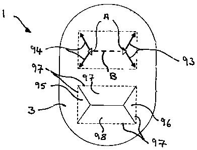
As can be seen in Figure 26, each piercing head 85 comprises a pair of
generally "U"
shaped elements 85a, 85b. Each U-shaped element comprises a pair of uprights
86
upstanding from the surface 34,34a of the piercing element on either side of
an airflow
aperture 37,38. A bridging portion 87 extends from the top of each facing pair
of
uprights 86 at an upward angle and towards each other so that they meet at an
apex 88
at a mid-point between the uprights 86.
In addition to being angled in an upward direction away from the apertures
37,38 and
the surface 34,34a of the piercing element, the bridging portions of each U-
shaped
element 85a,85b associated with the same aperture 37,38 are angled inwardly or
lean
towards each other in the same way in which the secondary cutting elements 48
of the
CA 02605035 2007-10-15
WO 2006/108877 PCT/EP2006/061607
-28-
embodiment of Figure 14 and 15 are angled inwardly and each form a V-shape
pointing
towards the primary cutting element 50.
The bridging portions 87 are multi-faceted and a cutting edge 89 is formed
between
two facets 90,91 which extends upwardly from each upright 86 towards a cutting
tip at
the apex 88 between the bridging portions 87. A further cutting edge 92
extends from
the apex 88 of each U-shaped piercing element 85a,85b in a direction towards
the other
U-shaped piercing element 85a,85b associated with the same aperture 37,38.
The cutting pattern produced in the lid 3 of a blister is illustrated in
Figure 27 from
which it will be understood that the apex 88 of each piercing head makes an
initial
incision in the lid 3 as indicated by "A" in the drawing. Further insertion of
the piercing
heads into the blister causes the cutting edges 89 to cut slits 93,94 in the
blister lid
extending from the point of initial incision "A" outward towards the edge of
the blister
lid 3. It will be appreciated that there is essentially no cutting element
extending
between each pair of U-shaped piercing heads and so the blister lid 3 is burst
open
between the initial points of incision "A", as indicated by dashed line "B" in
the
drawing. As a consequence of slitting and bursting through the blister lid 3,
two pairs
of generally triangular or trapezoidal shaped flaps 95,96,97,98 are formed
which are
folded along fold-lines 97 into the blister 1 by the piercing heads during
entry into the
blister 1. Although there is no cutting element extending between each pair of
piercing
heads, it will be appreciated that cutting edge 92 fulfils the function of
initiating a slit
extending between the initial points of incision "A" prior to bursting.
As has been described with reference to Figure 16, the piercing element may be
controlled so as to enter the blister 1 in a substantially linear path
extending at right-
angles to the plane of the blister lid 3. However, it is also envisaged that
the piercing
element may be mounted on a pivoting actuator (for example as disclosed in the
Applicant's co-pending international application no. PCT/GB2004/004416 which
has
now been published as WO 2005/037353 Al) such that the piercing heads follow
an
CA 02605035 2007-10-15
WO 2006/108877 PCT/EP2006/061607
-29-
arcuate path into a blister 1 and so approaches the lid 3 at a few degrees to
the normal
and has a component of movement in a direction parallel to the plane of the
lid 3. In
this case, use of the piercing heads described in the previous paragraph
results in the
flaps 95 furthest from the pivot axis being enlarged and, the flaps 96 closest
to the pivot
axis being reduced in size, as illustrated in Figure 28B.
To compensate, a more pronounced chamfer can be provided to the facet
extending
from the cutting edge of the piercing elements closest to the pivot axis.
However, care
must be taken not to increase the chamfer too much as this can have a
detrimental
effect on the piercing pattern, leading to inconsistent piercing. Piercing
elements having
piercing heads with more pronounced chamfers are illustrated in Figure 29A,
29B and
29C. In Figure 29A, the chamfer is pronounced to an intermediate stage whereas
in
Figure 29B, the chamfer is fu]Iy pronounced.
In a preferred embodiment illustrated in Figure 29C, the two facets 91 on the
piercing
elements closest to the pivot axis are twisted to form 3D curved surfaces that
intersect
to make a blade. The blade faces away from the pivot axis and in the direction
of any
component of movement in a direction parallel to the plane of the lid 3. The
blade is
angled at between 5 and 30 degrees and preferably between 10 and 20 degrees to
the
direction of protrusion of the piercing heads from their supports. In the
embodiment
of Figure 29C the angle is 15 degrees. The blade meets the facets 90 at a
point. During
piercing this point makes an initial incision. The blade then enters the foil
and ensures
that the V-shaped slit neccessary to achieve a repeatable burst during further
piercing is
maintained until the burst even when there is a component of movement parallel
to the
plane of the lid 3.
In a further variation of the aforementioned "double-U" shaped piercing head
illustrated in Figure 30, a bridge 99 extends between each pair of bridging
portions 87.
The bridge 99 acts to ensure that the bursting of the lid 3 between the
initial points of
incision marked "A" in Figure 27 is achieved in a more precise and repeatable
manner.
CA 02605035 2007-10-15
WO 2006/108877 PCT/EP2006/061607
-30-
It is also envisaged that the bridge 99 need not extend fully between each
pair of
bridging portions 87 and may be attached to only one. The bridge 99 may have a
generally curved peripheral surface, i.e. it could be cylindrical so that it
bursts through
the lid 3 as opposed to cutting it. It will also be appreciated that the
bridge 99 is located
beneath the apex 88 of the bridging portions 87 so that an initial incision
and slits are
cut by the cutting edges 92 prior to contact of the bridge 99 with the lid 3.
As
mentioned above initial slits are cut in the lid 3 between the two points of
initial
incision "A" by cutting edges 92 to facilitate a controlled bursting through
the lid 3 by
the bridge 99.
A second development of the envelope type piercing element, known as the
"double
cross" type piercer will now be described with reference to Figures 31 to 36.
It has previously been mentioned, in relation to the embodiment of Figures 14
and 15,
that the length of the primary cutting tooth 50 extending between the
secondary cutting
teeth 48 can be varied to the extent that the primary and secondary cutting
teeth 48,50
substantially form an "X" shape in plan view.
In the present embodiment, the primary cutting tooth 50 is omitted altogether
so that
the secondary cutting teeth 48 all meet at the same apex 100, as shown in
Figure 30.
Each cutting tooth 48 tapers to a pointed cutting tip 101 together they
produce a four
substantially triangular flaps, each of a similar shape and size. Each cutting
tooth 48
cuts from an initial insertion point (marked "B" in two opposite directions
towards the
apex and away from it towards the outer edges of the blister lid 3, as shown
by the
arrows in Figure 32. This makes for more consistent, controlled piercing of
the blister
lid 3.
The starting point for cuts in the blister lid 3 is ideally towards the outer
edges of the
blister 1 for optimum cutting where the lid 3 is better supported. However, in
order to
CA 02605035 2007-10-15
WO 2006/108877 PCT/EP2006/061607
-31-
allow the piercer to enter the blister 1 fully, it may be advantageous to move
the starting
point for the cuts up to half way towards the centre of the lid to allow the
points to fit
into the blister 1 after piercing i.e. so that the cutting tips 101 enter the
blister 1 towards
its deepest point.
In a modification of the above-described piercing element, illustrated in
Figure 33, the
piercing teeth 48 have a widened portion 102 near their root to facilitate
opening of the
flaps during piercing. In yet another modification, as shown in Figure 34,
nodes or
other protruberances 103 upstand from the surface 34, 34a of the piercing head
between the cutting teeth 48 and from the periphery of the apertures 37,38
which aid in
pushing open the flaps during piercing.
A final embodiment is called the "four point crown" piercing element and is
illustrated
in Figure 35. This embodiment is essentially a combination of the double U-
type
piercing element shown in Figure 26 and, the double cross type piercing
element shown
in Figure 30 and comprises four uprights 105 extending from the surface
34,34a. An
arm 106 extends angularly inward and upward from the end of each upright 105
and
meets at an apex 107. The end of each arm 106 is cut away to form four
triangular
shaped facets 108 each having a pointed tip 109. These tips 109 initiate four
incisions in
the blister lid very close to the centre of the lid (see incisions marked "C"
in Figure 36)
and each cutting tooth then cuts a slit in the lid extending outwardly and
inwardly from
each incision.
Many modifications and variations of the invention falling within the terms of
the
following claims will be apparent to those skilled in the art and the
foregoing
description should be regarded as a description of the preferred embodiments
only.