Language selection

Search

Patent 2605529 Summary

Third-party information liability

Some of the information on this Web page has been provided by external sources. The Government of Canada is not responsible for the accuracy, reliability or currency of the information supplied by external sources. Users wishing to rely upon this information should consult directly with the source of the information. Content provided by external sources is not subject to official languages, privacy and accessibility requirements.

Claims and Abstract availability

Any discrepancies in the text and image of the Claims and Abstract are due to differing posting times. Text of the Claims and Abstract are posted:

  • At the time the application is open to public inspection;
  • At the time of issue of the patent (grant).
(12) Patent: (11) CA 2605529
(54) English Title: DEPOSIT LOCK
(54) French Title: SERRURE A CONSIGNE
Status: Granted and Issued
Bibliographic Data
(51) International Patent Classification (IPC):
  • G07F 07/06 (2006.01)
(72) Inventors :
  • SONNENDORFER, HORST (Germany)
  • WIETH, FRANZ (Germany)
(73) Owners :
  • FRANZ WIETH
  • ANDREAS FILOSI
(71) Applicants :
  • FRANZ WIETH (Germany)
  • ANDREAS FILOSI (Germany)
(74) Agent: SMART & BIGGAR LP
(74) Associate agent:
(45) Issued: 2014-04-29
(86) PCT Filing Date: 2005-03-16
(87) Open to Public Inspection: 2006-09-21
Examination requested: 2007-09-13
Availability of licence: N/A
Dedicated to the Public: N/A
(25) Language of filing: English

Patent Cooperation Treaty (PCT): Yes
(86) PCT Filing Number: PCT/DE2005/000474
(87) International Publication Number: DE2005000474
(85) National Entry: 2007-09-13

(30) Application Priority Data: None

Abstracts

English Abstract


The invention relates to a deposit lock comprising a checking element which
controls the diameter of an inserted deposit element with respect to the
available value thereof and a key holding element, wherein said holding
element releases the key when the value is available.


French Abstract

La présente invention concerne une serrure à consigne comprenant un élément de vérification qui contrôle le diamètre de l'élément de consigne inséré quant à la validité de sa valeur, ainsi que des éléments de retenue pour une clé. Les éléments de retenue ne libèrent la clé que si la valeur est valable.

Claims

Note: Claims are shown in the official language in which they were submitted.

-7-
Claims
1.A deposit lock comprising:
an insertion opening in a housing through which a deposit
element can be inserted,
a checking element that can be used to check the validity
of the deposit element,
a locking element for a key, having two alternative
positions, in which case the key can be fixed in the
holding position and the key can be released in the
release position, and in which case the locking element
assumes the release position, released by the insertion
of the deposit element, until a release point,
characterized in that
wherein said checking element records the diameter of the
inserted deposit element and, if the diameter has a valid
value, the lock can be released and the key can be
released; and
wherein said checking element is adapted to retain the
deposit element in its position.
2.The deposit lock as claimed in claim 1, wherein
the checking element is mounted in a guide with respect
to the housing of the lock, which guide allows a
longitudinal movement of the checking element along a
predetermined path and, in addition, a rotary movement of
the checking element at one specific position on the
path.
3.The deposit lock as claimed in claim 1 or 2, wherein

-8-
the guide in which the checking element is mounted has
elongated holes and bolts, which engage in these
elongated holes, as well as a recess adjacent to at least
one of the elongated holes.
4.The deposit lock as claimed in any one of claims 1 to 3,
wherein
a spring pushes the checking element against the outer
wall of the deposit element.
5.The deposit lock as claimed in any one of claims 1 to 4,
wherein
the axes of the elongated holes run essentially parallel
to one another.
6.A deposit lock comprising:
an insertion opening in a housing through which a deposit
element can be inserted,
a locking element for a key, the locking element having
two alternative positions:
a holding position in which the key can be fixed;
and
a release position in which the key can be released;
wherein, responsive to insertion of the deposit element,
the locking element assumes the release position,
a checking element adapted to, responsive to insertion of
the deposit element,
retain the deposit element in its position,
record the diameter of the deposit element and,

-9-
upon determining the diameter has a valid value,
allowing the locking element to assumes the release
position so the key can be released.

Description

Note: Descriptions are shown in the official language in which they were submitted.


CA 02605529 2007-09-13
wO 2006/097055 PCT/DE2005/000474
Deposit lock
The invention relates to a deposit lock, which has a
checking element for a deposit, and a locking element
for a key.
A deposit lock such as this is known, for example, from
EP 1035523 A2. Deposit locks such as these are used,
for example, for shopping trolleys, which are connected
to one another via a security chain, which is attached
to the key, when in the parked state. In order to allow
a shopping trolley such as this to be used, a deposit
element, for example a deposit coin, must be inserted
into the lock.
The deposit coins differ in their value and in their
size. Normally, relatively small coins have a lower
value than relatively large coins.
In the case of known locks, it is necessary to insert a
deposit coin of the predetermined value in order to
release the key.
In the cited prior art, the maximum permissible coin
diameter is checked by means of an insertion slot which
is matched to the predetermined coin diameter and whose
dimensions prevent coins whose diameter is larger than
the maximum permissible specified diameter from being
inserted. In addition to this maximum value check, the
diameter of the deposit coin is investigated within the
deposit lock to determine whether the diameter is less
than a predetermined minimum value.
Within the lock, the minimum value for the diameter of
the coin is in this case checked as follows: one side
of the edge of the coin rests on a stationary guide,
and the opposite side of the coin edge is recorded by a
scanning element. If the coin is of the predetermined

I CA 02605529 2007-09-13
WO 2006/097055 PCT/DE2005/000474
- 2 -
minimum diameter, the scanning element releases the
release mechanism for the key.
It has now been found that known locks can also be
released by smaller, and therefore less valuable, coins
by manipulation. The smaller coins are first of all
partially inserted into the insertion slot of the
deposit lock, and a larger and therefore correct
diameter is then simulated by moving the inserted coin
laterally with respect to the insertion direction. This
then overcomes the deposit lock.
In order to make such manipulation more difficult,
deposit locks are known, such as those from
DE 199 17 391 Al, which use two scanning elements that
act independently of one another to check the diameter
within the deposit lock. These scanning elements record
the coin edge from different sides and then each
autonomously check it for the predetermined minimum
diameter. A smaller coin can simulate a correct coin by
being moved laterally within the housing only at one of
the two scanning elements, thus making it possible to
prevent the lock from being released. However, this
solution has the disadvantage that the number of parts
is increased because there are twice as many scanning
elements.
The object of the invention is therefore to provide a
deposit lock in which it is harder to release the lock
with a different coin than the intended coin, while
furthermore keeping the number of parts used small.
This object is achieved by the subject matter of the
main claim, and the dependent claims relate to
advantageous refinements and/or further developments of
the invention.

CA 02605529 2007-09-13
WO 2006/097055 PCT/DE2005/000474
- 3 -
The considerations which have led to the creation of
the present invention are based on the idea that
increased security against manipulation is provided if
the security chain can be released only when the single
scanning element within the lock checks the diameter of
the inserted coin to determine whether the diameter is
less than or greater than the predetermined value. The
security chain is then released only when it is found
that this diameter has been neither undershot nor
overshot. This narrowly limited range can be simulated
only with difficulty by lateral movement of the coin in
the deposit lock. At the same time, one scanning
element is sufficient to determine whether the diameter
is within the value range, thus advantageously keeping
the number of parts required low.
Since all the checks are carried out within the lock,
the insertion slot need no longer carry out the
function of checking the maximum diameter. It is
advantageously possible to use a standard insertion
slot, and there is no need for the different insertion
slots, each matched to one specific coin diameter. This
advantageously simplifies the parts administration. The
locks for different coins now differ only in the
configuration of the single scanning element in the
interior of the lock.
One possible exemplary embodiment of the invention will
be explained in more detail in the following text with
reference to the drawings, in which:
Figure 1 shows the view from above, in the form of a
section illustration, of the interior of the lock with
a coin,
Figure 2 shows the lock as shown in Figure 1, in a side
view sectioned along the line II-II,
Figure 3 shows the view from Figure 1 with the scanning
element initiated,

CA 02605529 2007-09-13
WO 2006/097055 PCT/DE2005/000474
- 4 -
Figure 4 shows the situation shown in Figure 1, with a
coin that is too large, and
Figure 5 shows the situation shown in Figure 1, with a
coin that is too small.
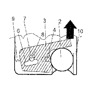
Figure 1 shows the housing 1 of the lock with the cover
open. For clarity reasons, only that area of the
housing 1 in which the coin 2 is checked is shown. A
scanning element 3 is provided in order to check the
diameter of the coin 2. An inserted coin 2 which
corresponds to the predetermined diameter can then be
pushed in further in the insertion direction then
release a key, which is likewise not shown, via a
mechanism that is not shown.
In order to explain the method of operation, reference
will be made to the section illustration shown in
Figure 2, as well as to Figure 1. The scanning element
3 is essentially flat and has a bolt 4 which projects
downwards. This bolt projects into an elongated hole 5,
which is located in the housing 1.
For its part, the scanning element 3 has a recess 6.
The shape of this recess 6 corresponds to an elongated
hole with an additional side recess 7 on one of the
longitudinal sides. A bolt 8 projects from the housing
1 into this recess 6. The scanning element 3 is pressed
by a spring 9 against one side of the outer edge of the
coin 2, while the other, opposite side of the outer
edge of the coin rests on a side guide 10. The
longitudinal axis through the elongated hole 5 runs
parallel to the longitudinal axis of the areas 6a and
6b, which are like elongated holes, of the recess 6.
The freedom of movement of the scanning element 3 with
respect to the housing 1 in the x-y direction is
defined by the shape of the elongated hole 5 and the
areas of the recess 6 which are like elongated holes
and in which the bolts 4 and 8 are located.

CA 02605529 2007-09-13
WO 2006/097055 PCT/DE2005/000474
- 5 -
The freedom of movement is provided mainly only in the
x-direction since, in most positions which the scanning
element 3 can assume, the two. If a coin with the
correct diameter is located in the lock, as shown in
Figures 1, 2 and 3, then the bolt 8 is located
precisely opposite the side recess 7. If the coin is
now pushed further into the lock, then the scanning
element can also move with a y-component, by the bolt 8
entering the side recess 7, and the scanning element 3
pivoting around the bolt 4. This pivoting movement
initiates the downstream mechanism to release the key.
Figure 4 now shows the situation with a coin 2a that is
too small. The bolt 8 is located in the area 6a, which
is like an elongated hole, of the recess 6. No pivoting
movement is possible.
The same situation occurs when a coin 2b that is too
large is inserted. In this situation, the bolt 8 is
located in the area 6b, which is like an elongated
hole, of the recess 6, and, once again no pivoting
movement of the scanning element 3 is possible in this
case.
As explained by the figures and the associated
description, the present invention advantageously means
that a pivoting movement is possible only when the
scanning element 3 is located precisely in the position
in which the bolt 8 is precisely opposite the side
recess 7. The smaller the difference between the width
of the recess 7 and the thickness of the bolt, the less
is the tolerance for the coin diameter.
In the event of a manipulation attempt, in which an
attempt is made to overcome the lock using a smaller
coin, the person carrying out the manipulation will
face the difficulty of first of all having to move the

CA 02605529 2007-09-13
WO 2006/097055 PCT/DE2005/000474
- 6 -
scanning element 3 to the exact position in the x-
direction using a small coin 2a, and then of pushing
this coin further into the lock in the y-direction
without, however in the meantime changing the x-
position of the scanning element.
In addition, the person carrying out the manipulation
will be impeded in his attempt to carry out such misuse
by the force of the spring 9, because this always
presses the scanning element 3 into a position in which
it is not possible to release the lock.
In a further refinement of the invention, which is not
illustrated as a figure, it is possible to define two
or more discrete values for a valid coin diameter.
For this purpose, further side recesses similar to the
recess 7 must be provided. For example, the further
side recess can be provided for the elongated hole 5.
The lock is now also released when the bolt 4 is
opposite the additional recess.
The lock can then be released using different coins,
thus improving the user convenience without there being
a certain range of valid diameters. A range such as
this would make it easier for a person carrying out
manipulation to overcome the lock using a smaller coin.
According to the invention, there is actually no such
range, thus advantageously making manipulation more
difficult.
The described deposit lock according to the invention
can be used wherever an object is made available to a
user for a certain time and the value of the deposit
coin is intended to motivate the user to return the
object loaned to him to a predetermined return location
again.

Representative Drawing
A single figure which represents the drawing illustrating the invention.
Administrative Status

2024-08-01:As part of the Next Generation Patents (NGP) transition, the Canadian Patents Database (CPD) now contains a more detailed Event History, which replicates the Event Log of our new back-office solution.

Please note that "Inactive:" events refers to events no longer in use in our new back-office solution.

For a clearer understanding of the status of the application/patent presented on this page, the site Disclaimer , as well as the definitions for Patent , Event History , Maintenance Fee  and Payment History  should be consulted.

Event History

Description Date
Common Representative Appointed 2019-10-30
Change of Address or Method of Correspondence Request Received 2018-01-12
Inactive: Correspondence - Prosecution 2018-01-04
Small Entity Declaration Determined Compliant 2018-01-04
Small Entity Declaration Request Received 2017-09-25
Small Entity Declaration Determined Compliant 2017-09-25
Small Entity Declaration Request Received 2017-09-25
Letter Sent 2017-08-29
Inactive: Multiple transfers 2017-08-09
Grant by Issuance 2014-04-29
Inactive: Cover page published 2014-04-28
Pre-grant 2014-01-10
Inactive: Final fee received 2014-01-10
Notice of Allowance is Issued 2013-08-13
Letter Sent 2013-08-13
Notice of Allowance is Issued 2013-08-13
Inactive: Approved for allowance (AFA) 2013-07-15
Amendment Received - Voluntary Amendment 2013-02-26
Inactive: S.30(2) Rules - Examiner requisition 2012-08-31
Amendment Received - Voluntary Amendment 2011-12-29
Inactive: S.30(2) Rules - Examiner requisition 2011-06-30
Amendment Received - Voluntary Amendment 2010-11-15
Inactive: S.30(2) Rules - Examiner requisition 2010-05-14
Letter Sent 2010-03-11
Reinstatement Requirements Deemed Compliant for All Abandonment Reasons 2010-02-18
Deemed Abandoned - Failure to Respond to Maintenance Fee Notice 2009-03-16
Inactive: Cover page published 2008-01-21
Inactive: Acknowledgment of national entry - RFE 2008-01-17
Letter Sent 2008-01-17
Inactive: Inventor deleted 2008-01-17
Inactive: First IPC assigned 2007-11-16
Application Received - PCT 2007-11-15
National Entry Requirements Determined Compliant 2007-09-13
Request for Examination Requirements Determined Compliant 2007-09-13
All Requirements for Examination Determined Compliant 2007-09-13
National Entry Requirements Determined Compliant 2007-09-13
Application Published (Open to Public Inspection) 2006-09-21

Abandonment History

Abandonment Date Reason Reinstatement Date
2009-03-16

Maintenance Fee

The last payment was received on 2014-02-20

Note : If the full payment has not been received on or before the date indicated, a further fee may be required which may be one of the following

  • the reinstatement fee;
  • the late payment fee; or
  • additional fee to reverse deemed expiry.

Patent fees are adjusted on the 1st of January every year. The amounts above are the current amounts if received by December 31 of the current year.
Please refer to the CIPO Patent Fees web page to see all current fee amounts.

Owners on Record

Note: Records showing the ownership history in alphabetical order.

Current Owners on Record
FRANZ WIETH
ANDREAS FILOSI
Past Owners on Record
HORST SONNENDORFER
Past Owners that do not appear in the "Owners on Record" listing will appear in other documentation within the application.
Documents

To view selected files, please enter reCAPTCHA code :


To view images, click a link in the Document Description column (Temporarily unavailable). To download the documents, select one or more checkboxes in the first column and then click the "Download Selected in PDF format (Zip Archive)" or the "Download Selected as Single PDF" button.

List of published and non-published patent-specific documents on the CPD .

If you have any difficulty accessing content, you can call the Client Service Centre at 1-866-997-1936 or send them an e-mail at CIPO Client Service Centre.

({010=All Documents, 020=As Filed, 030=As Open to Public Inspection, 040=At Issuance, 050=Examination, 060=Incoming Correspondence, 070=Miscellaneous, 080=Outgoing Correspondence, 090=Payment})


Document
Description 
Date
(yyyy-mm-dd) 
Number of pages   Size of Image (KB) 
Description 2007-09-12 6 237
Representative drawing 2007-09-12 1 6
Drawings 2007-09-12 1 25
Claims 2007-09-12 2 44
Abstract 2007-09-12 1 63
Claims 2010-11-14 3 62
Representative drawing 2014-03-31 1 8
Maintenance fee payment 2024-02-27 12 463
Acknowledgement of Request for Examination 2008-01-16 1 176
Notice of National Entry 2008-01-16 1 202
Courtesy - Abandonment Letter (Maintenance Fee) 2009-05-10 1 172
Notice of Reinstatement 2010-03-10 1 164
Commissioner's Notice - Application Found Allowable 2013-08-12 1 163
PCT 2007-10-31 2 100
PCT 2007-09-12 7 211
PCT 2007-10-15 1 27
Fees 2008-02-18 1 34
Fees 2010-02-17 1 34
Fees 2010-02-17 1 35
Fees 2011-02-16 1 37
Correspondence 2014-01-09 1 51
Maintenance fee payment 2017-03-06 1 24
Prosecution correspondence 2018-01-03 26 782
Small entity declaration 2017-09-24 4 114