Language selection

Search

Patent 2605835 Summary

Third-party information liability

Some of the information on this Web page has been provided by external sources. The Government of Canada is not responsible for the accuracy, reliability or currency of the information supplied by external sources. Users wishing to rely upon this information should consult directly with the source of the information. Content provided by external sources is not subject to official languages, privacy and accessibility requirements.

Claims and Abstract availability

Any discrepancies in the text and image of the Claims and Abstract are due to differing posting times. Text of the Claims and Abstract are posted:

  • At the time the application is open to public inspection;
  • At the time of issue of the patent (grant).
(12) Patent Application: (11) CA 2605835
(54) English Title: WIND BOOSTER
(54) French Title: SURPRESSEUR EOLIEN
Status: Deemed Abandoned and Beyond the Period of Reinstatement - Pending Response to Notice of Disregarded Communication
Bibliographic Data
Abstracts

English Abstract


The present invention is a method and apparatus to increase air speed through
a turbine
such as in a wind power generator. The method comprises creating a low
pressure area behind
(or, downstream) of the turbine so as to cause the wind entering the turbine
to be accelerated
thereby adding torque for the turbine to turn the generator. The apparatus
comprises a
generally conic shaped, open-ended hood that extends behind the turbine to act
as an airfoil
and so cause an increase in air speed along its lengthening outer surface,
which, in turn,
lowers the pressure in the interior of the hood. Wind will thus be 'drawn'
into the resulting
partial vacuum thereby raising wind speed. Also disclosed is a mobile use
where a turbine
generator is shrouded to the the rear of a vehicle with an opening to enable
fir flow to enter
the shroud and drive the turbine as the air seeks the naturally-occurring low
pressure area to
the rear of the vehicle and shrouded turbine.


Claims

Note: Claims are shown in the official language in which they were submitted.

CLAIMS
The embodiments of the invention in which an exclusive property or privilege
is claimed are
defined as follows:
1.
2.
3.
4.
5.

Description

Note: Descriptions are shown in the official language in which they were submitted.


CA 02605835 2007-10-03
SPECIFICATIONS
FIELD OF THE INVENTION
A vacuum assisted turbine to improve the performance of wind generators, may
also be
used to capture some of the normally waster aerodynamic energy behind a moving
vehicle.
BACKGROUND OF THE INVENTION
Wind powered electricity generation occurs when a moving mass of air strikes
the
aerodynamic shape of the turbine blades creating a rotational torque which
turns an electrical
generator. More torque (and electricity) comes from higher wind speed by a
cubic factor, that
is, a doubling of wind speed yields an eight-fold increase in turbine torque.
By creating a
partial vacuum behind the turbine, such performance increase can achieved very
cheaply.
Such a partial vacuum can be created by using a aerodynamic hood behind the
turbine which
may be conveniently funnel- or conically shaped, to operate as an airfoil
(i.e., a propellor or
fan blade or an aircraft wing or a ship's sail) whereby the increase in speed
of the wind
flowing along the longer outer surface creates a lower pressure on its inner
surface. In the
instant invention the wind speed is increased about the hood's exterior due to
the increasing
diameter of the conical flow path on the exterior of the hood and this lowers
pressure inside.
Wind will thus be accelerated through the turbine to fill the low pressure
behind. The instant
invention which might be considered a`vacuum turbine', may also be used behind
a moving
vehicle, i.e., in the slipstream so as to provide additional electrical power
for the vehicle.
SUMMARY OF THE INVENTION
To accelerate the wind for a wind powered generator, one needs only to lower
pressure on
the downwind side of the turbine as compared to the inlet side. By adding an
dynamic hood
sealed to the rear of the turbine and preferably with a diameter increasing
rearwards from the
turbine, the desired lower pressure is easily and cheaply achieved. The hood
may be as
1

CA 02605835 2007-10-03
simple as a flat, washer-like ring surrounding the turbine blades or a
developed shape like a
rocket's nozzle that optimizes the creation of the low pressure. The hood may
`sealed' to the
rear the turbine via a separate ring or hoop in order to prevent unwanted blow-
by of air into
the low pressure in the funnel. In other words, ideally, the turbine tips
should rotate within a
circular housing onto the rear of which, the hood is sealedly attached. The
use of a tower,
building or other structure to act as the hood of the instant invention is
also contemplated.
Multiple smaller turbines may be combined in such a structure. For example an
unused
building can have the windward (facing the wind) side with turbines in window
openings to
inner rooms and the leeward side (sheltered from the wind) open and connected
via said
rooms to the turbines whereby the low pressure is on the entire leeward side
to accelerate
wind flow through the turbines on the windward side through the rooms and out
the leeward
side.
In a moving vehicle there is a naturally occurring low pressure wake behind
the vehicle
which the instant invention exploits to generate electricity which may be used
to charge
batteries, operate electrical equipment (blowers, radios, wipers, etc.) and
engine pumps (oil,
water, supercharger). In this application the turbine is shrouded to the
vehicle with the one
side of the turbine exposed to the vacuum or wake. An opening in the shroud
allows air
flowing about the vehicle (sides, top and/or under) to enter the shroud and
thus be drawn
through the turbine by and into the low pressure vacuum or wake. In hybrid
vehicles this will
enable a longer range as the batteries can be charged using waste energy, In
regular vehicles
the fuel economy and the performance will benefit from the reduced generating
needs which
are being at least partially supplied by the turbine capturing waste energy
from the air flow.
BRIEF DESCRIPTION OF THE DRAWINGS
2

CA 02605835 2007-10-03
Figure 1 shows a frontal view upwind of the wind powered machine with the hood
of the
instant invention surrounding the turbine and tapering to a larger diameter
down
wind;
Figure 2 is a side view of the same embodiment showing the funnel-shaped hood;
Figure 3 shows the hood having a complex shape for higher performance;
Figure 4 shows the simplest embodiment that of a flat washer-shaper ring;
Figure 5 shows a steep, short hood;
Figure 6 shows an adjustable hood that can be automatically adjusted according
to wind
conditions.
Figure 7 shows a front (windward) side of a tower version of the hood with
multiple
turbines;
Figure 8 shows a top view of the same embodiment;
Figure 9 shows a vehicle with rear mounted turbine.
DETAILED DESCRIPTION OF THE INVENTION
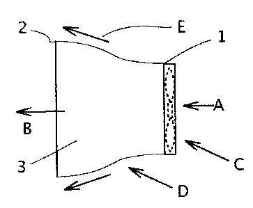
In the Figures, hood D has a windward side I and a leeward side 2. A portion
of ambient
wind A is forced to flow E outwardly along the expanding diameter (longer
distance) of hood
D and therefore to increase its speed. And a portion of wind A enters turbine
C at ambient
speed. Hood interior 3 is thereby subjected to low pressure from this flow-
speed (E minus A)
differential in accordance with Bernoulli's famous principle: "an increase in
velocity occurs
simultaneously with decrease in pressure".
In Figs 1-6 the hood D is shown in different configurations. In Figs 7 and 8,
the hood D is
in the form of a curved supporting structure or tower wherein are located the
turbines. Base 4
may provide a means to allow the hood D to rotate to correct or adjust for
wind direction.
3

CA 02605835 2007-10-03
In Fig 6 the hood D is shown to be adjustable in length and angle although it
may be
adjusted as to angle and also curvature as shown in Fig 3 where it takes the
shape of a rocket
nozzle. In Fig 5 the hood D is a simple torus shaped disc like a common metal
washer used
with nuts and bolts.
For maximum performance, the shape of hood D must take into account likely
wind
conditions and the diameter of the turbine and its height off the ground. The
hood D may
comprise an open frame-like structure covered with a surfacing material such
as plastic or
concrete. Different multiple turbine configurations are contemplated such as
in a linear
arrangement in a wall-type hood with a curved top edge.
In Fig 9 moving vehicle E (dotted outline) has a (low pressure) wake F behind.
Shroud D'
and turbine C are attached to the rear of the vehicle E. Air flow A (top,
sides and under)
naturally moves along the outer surfaces of the vehicle to thereby create wake
F aft of the
vehicle. Shroud surface 11 has opening 10 to allow air A to enter and pass
through turbine C
and exit at B to enter wake F. Opening 10 may be holes, slits, NACA ducts
(National
Advisory Committee for Aeronautics also known as submerged ducts), scoops,
peripheral
gaps, or there may be an entire section of shroud 11 missing, such as the
entire lower surface.
However it is done, enough air has to be able to enter shroud D' to turn the
turbine yet
continue to create adequate wake F aft of the turbine, and, there should be no
increase in air
resistance to the vehicle. In this instant invention, turbine C therefore,
uses normally wasted
aerodynamic energy to drive an electrical alternator or generator (not shown)
which then
connects into the vehicles wiring harness or to other devices requiring
electric energy or to
batteries of an electric power supply.
The vehicle exhaust may also add to the volume of fluid passing through the
turbine C to
provide more electrical output although at low speeds or idle, with a internal
combustion
engine, heat may be a problem.
4

Representative Drawing
A single figure which represents the drawing illustrating the invention.
Administrative Status

2024-08-01:As part of the Next Generation Patents (NGP) transition, the Canadian Patents Database (CPD) now contains a more detailed Event History, which replicates the Event Log of our new back-office solution.

Please note that "Inactive:" events refers to events no longer in use in our new back-office solution.

For a clearer understanding of the status of the application/patent presented on this page, the site Disclaimer , as well as the definitions for Patent , Event History , Maintenance Fee  and Payment History  should be consulted.

Event History

Description Date
Application Not Reinstated by Deadline 2012-10-03
Time Limit for Reversal Expired 2012-10-03
Inactive: Adhoc Request Documented 2012-07-05
Deemed Abandoned - Failure to Respond to Maintenance Fee Notice 2011-10-03
Application Published (Open to Public Inspection) 2009-04-03
Inactive: Cover page published 2009-04-02
Inactive: Correspondence - Formalities 2008-12-29
Inactive: IPC assigned 2007-12-10
Inactive: First IPC assigned 2007-12-10
Inactive: IPC assigned 2007-12-10
Inactive: Filing certificate - No RFE (English) 2007-11-16
Application Received - Regular National 2007-11-16
Amendment Received - Voluntary Amendment 2007-10-22
Small Entity Declaration Determined Compliant 2007-10-03

Abandonment History

Abandonment Date Reason Reinstatement Date
2011-10-03

Maintenance Fee

The last payment was received on 2010-07-28

Note : If the full payment has not been received on or before the date indicated, a further fee may be required which may be one of the following

  • the reinstatement fee;
  • the late payment fee; or
  • additional fee to reverse deemed expiry.

Patent fees are adjusted on the 1st of January every year. The amounts above are the current amounts if received by December 31 of the current year.
Please refer to the CIPO Patent Fees web page to see all current fee amounts.

Fee History

Fee Type Anniversary Year Due Date Paid Date
Application fee - small 2007-10-03
MF (application, 2nd anniv.) - small 02 2009-10-05 2009-08-10
MF (application, 3rd anniv.) - small 03 2010-10-04 2010-07-28
Owners on Record

Note: Records showing the ownership history in alphabetical order.

Current Owners on Record
WINSTON MACKELVIE
Past Owners on Record
None
Past Owners that do not appear in the "Owners on Record" listing will appear in other documentation within the application.
Documents

To view selected files, please enter reCAPTCHA code :


To view images, click a link in the Document Description column. To download the documents, select one or more checkboxes in the first column and then click the "Download Selected in PDF format (Zip Archive)" or the "Download Selected as Single PDF" button.

List of published and non-published patent-specific documents on the CPD .

If you have any difficulty accessing content, you can call the Client Service Centre at 1-866-997-1936 or send them an e-mail at CIPO Client Service Centre.


Document
Description 
Date
(yyyy-mm-dd) 
Number of pages   Size of Image (KB) 
Description 2007-10-02 4 163
Abstract 2007-10-02 1 22
Drawings 2007-10-02 2 32
Claims 2007-10-02 1 4
Representative drawing 2008-11-06 1 5
Claims 2008-12-28 1 17
Abstract 2007-10-21 1 17
Description 2007-10-21 3 109
Filing Certificate (English) 2007-11-15 1 156
Notice: Maintenance Fee Reminder 2009-07-05 1 118
Notice: Maintenance Fee Reminder 2010-07-05 1 122
Notice: Maintenance Fee Reminder 2011-07-04 1 122
Courtesy - Abandonment Letter (Maintenance Fee) 2011-11-27 1 173
Second Notice: Maintenance Fee Reminder 2012-04-03 1 119
Reminder - Request for Examination 2012-06-04 1 115
Notice: Maintenance Fee Reminder 2012-07-03 1 128
Correspondence 2007-11-15 1 19
Correspondence 2007-10-21 6 148
Fees 2009-08-09 1 54
Correspondence 2008-12-28 2 35
Fees 2010-07-27 1 87