Note: Descriptions are shown in the official language in which they were submitted.
CA 02606071 2007-10-25
WO 2006/114578 PCT/GB2006/001411
-1-
Device For The Preparation Of Food
The present invention relates to a device for the
preparation of food and in particular but not exclusively
to a device for at least partially cutting a food product
into discrete sections.
The preparation of food and articles such as
sandwiches or toasted articles have the drawback that the
product has to be cut into regular sections during the
course of preparation. In particular, in the case of
bread or dough based articles, which are not solid and
which can be frangible due to aeration of the product, it
can be difficult to cut such items into regular shaped
articles due to the inherent flexibility of the product.
This can mean that there is wastage of food due to poor
cutting and also if the final product is poorly cut and
hence badly presented, this can lead to wastage because,
if the food if irregularly cut, this can alter the
desirability of the final product because of its
aesthetic appeal.
An example of the disadvantages is where bread is
toasted and cut into thin elongate sections so that it
can be dipped into sauces or spreads or even into eggs.
If the toasted bread is irregularly shaped, there is a
disadvantage that the toasted finger of bread may not be
of regular dimensions which means that it may not be
possible to insert the whole section into a predefined
aperture that may have been cut into an egg. Also where
the food product has been cut into relatively thin
sections, due to the thinness of the food product
produced, lengths of the food product may become detached
when carrying an extra food item into which the product
has been dipped which can lead to spillage.
CA 02606071 2007-10-25
WO 2006/114578 PCT/GB2006/001411
-2-
A further problem associated with toasted food
products that are ultimately to be cut into sections or
units is that because of toasting, the food product
becomes brittle and when it is cut, crumbs are formed,
which can fall onto surrounding surfaces during cutting.
This is not only undesirable due to food wastage but can
also be unhygienic because any waste food needs to be
cleaned up from a food preparation area in order not to
attract pests which can have food hygiene implications,
especially in commercial food preparation establishments.
In addition, if a food item is for consumption by a
child, the food product often needs to be cut into
smaller sections for ease of consumption. This
necessitates the food being cut with a knife, which is
undesirable because children are less dextrous and
careful than adults and may cut themselves when using the
knife. Hence an adult needs to be on hand to prepare the
food which may not always be possible, leading to health
and safety implications for known methods of food
preparation involving the cutting of food into portions.
The present invention seeks to overcome the problems
associated with the prior art by providing a food
preparation device that can be used to safely and cleanly
separate a food product into discrete sections. The
product may be a product that is in the process of being
prepared such as a par baked dough product or it can be a
product in its final form, such as a toasted article that
is ready for consumption.
According to the present invention, there is
provided a device for food preparation comprising a main
body adapted for coming into contact with a food product
to be prepared, the device having an array of discrete
cutting edges extending from the main body, said cutting
CA 02606071 2007-10-25
WO 2006/114578 PCT/GB2006/001411
-3-
edges being spaced from one another to provide a series
of discrete cuts in the product which are spaced from one
another leaving areas of the food product joined
together, where no cutting occurs.
Preferably, the array of spaced cutting edges
comprises a first set of cutting edges extending in a
first direction and a second set of cutting edges
extending in a second direction.
It is envisaged that the first set of cutting edges
comprises a series of parallel edges with the second set
of cutting edges extending a distance along each end of
said first set of cutting edges.
Preferably, the second set of cutting edges
comprises two cutting edges, with one of said cutting
edges extending substantially perpendicular to and along
a first end of the first set of parallel cutting edges,
being arranged in spaced linear alignment, and the second
cutting edge of said second set of cutting edges,
extending at the other end of said spaced linear
arrangement of first cutting edges.
In a preferred arrangement, one or more of each of
the first set of cutting edges has a recess along the
length of said cutting edges. Preferably, the recess is
substantially towards the centre of the cutting edge,
however, a series of recesses may be positioned at
separate points along a cutting edge.
Preferably, one or more of the edges forming the
second set array of cutting edges has a raised edge
extending outwardly from said cutting edge. Preferably,
the raised edge or extension is positioned to be spaced
between two parallel cutting edges of the first array.
It is envisaged that the raised edge is substantially at
CA 02606071 2007-10-25
WO 2006/114578 PCT/GB2006/001411
-4-
a point equidistant between two of the parallel cutting
edges of the first array.
The arrangement of an array of first and second
cutting edges with raised and recessed areas on the
edges, forms a series of cutting and pressing edges which
come into contact with the surface of a food product. The
second set of cutting edges, which are positioned along
and perpendicular to the parallel edges of the first set
of cutting edges form a section having alternate recessed
and raised edges.
It is envisaged that each of the second set of
cutting edges has a cutting edge which does not extend
the whole distance between the cutting edges of the first
array thereby forming two uncut areas between the areas
cut by the first array, these uncut areas being at the
junction where the first and second cutting edges meet.
By having a series of uncut areas, this maintains the
portions of the food products that are being cut as a
one-piece product with the uncut areas of the food
product providing links or bridges to hold the food
product together prior to further treatment. The areas
where the cut sections of food product are held together
are relatively thin and provide weakened areas in the
product where sections of the product can be separated
relatively easily. It is preferred that the first and
second cutting edges are arranged such that a series of
parallel sections of a food product are produced and two
perpendicular food sections are produced are either end
of the parallel sections of product. These outer
sections can be pulled from the ends of the first
sections and separated, while the parallel sections of
the food product can be separated from one another by
pulling the sections which will break from one another at
CA 02606071 2007-10-25
WO 2006/114578 PCT/GB2006/001411
-5-
the bridge areas that remain after areas along a line
separating the sections have been cut.
It is envisaged that all cutting edges are
chamfered. This provides a sharper cutting edge to cut
sections. However, areas of the cutting edge may be flat
faces to provide a simple pressing surface.
Preferably, the device is formed of one or more or a
combination of rubber, metal or food grade plastic.
It is envisaged that in a preferred arrangement, the
main body includes a handle so that the cutting edges can
be impressed upon a food product.
In a preferred arrangement, the main body forms a
convex curve with the cutting edges extending outwardly
from the curved surface. This allows for the device to
be placed on an object and rocked back and forth thereby
providing a cutting action.
It is envisaged that the first set of cutting edges
extends substantially perpendicular to the curved
surface. This means that the cutting edges do not fan
out to match the curve of the main body. However, if
desired the cutting edges can be angled such that they
fan out in accordance with the curve of the main body.
Preferably, a handle extends from a rear surface of
the device, remote from the cutting edges, said handle
preferably having grip regions so that a firm force can
be applied to the device as it is being rocked back and
forth over the surface of a product.
Preferably, the food product is a farinaceous
product, for example bread or dough product. However, it
is envisaged that the device is suitable for other types
of food products for. example meat products, or other
products to be baked.
CA 02606071 2007-10-25
WO 2006/114578 PCT/GB2006/001411
-6-
According to a further embodiment of the invention,
there is provided a method of cutting a food product, by
a cutting device having cutting edges and recess edges is
pressed against the food product so that the product is
cut in similar localities while cutting does not occur in
other localities so that a complete product remains can
be processed for example by toasting.
A preferred embodiment of the invention will now be
described by way of example only with reference to and as
illustrated in the accompanying figures in which;
Figure 1 shows a cutting device according to an
embodiment of the invention;
Figures 2 shows in detail an area of the cutting
device as shown in Figure 1;
Figure 3 shows the cutting pattern of a device as
shown in Figure 1;
Figure 4 shows how the array of food sections as
shown in Figure 3 can be separated from another;
Figure 5 shows an alternative arrangement of a
cutting device, complete with handle; and
Figure 6 shows the cutting array as produced by the
device of Figure 5.
Figure 7 shows a plan view of a section through the
device.
Figure 8 shows a side view of a cutting device
according to an embodiment of the invention.
Figure 9 shows an end view of a cutting device
according to an embodiment of the invention; and
Figure 10 show a plan view of an array of first and
second cutting edges of a device as shown in Figures 8
and 9.
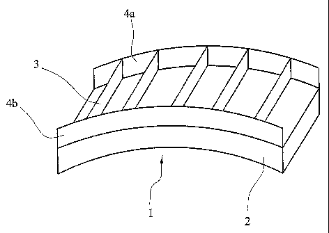
A cutting device according to an embodiment of the
invention is generally shown as 1 in Figure 1. The
CA 02606071 2007-10-25
WO 2006/114578 PCT/GB2006/001411
-7-
device, which is used to prepare food products comprises
a main body 2 which is of a convex shape, although the
face may be flat. A convex shape allows the device to be
rocked back and forth over the surface of a food product
so less force is needed to be applied to ensure cutting.
Extending from a convex face of the device, there is
a series of cutting edges 3 forming a first set of
cutting edges arranged parallel to one another and
extending width-ways down the length of the device 2.
Perpendicular to and at either end of the first set of
cutting edges 3 is a second set of cutting edges provided
as two cutting edges 4a and 4b. The height of the
cutting edges 3 is substantially that of the height of
the cutting edge 4a and 4b.
Figure 2 shows a detailed arrangement of the cutting
edges 3 and 4, which include not only cutting sections
but pressing sections too. The cutting edges 3 and 4 are
perpendicular to one another and meet at a series of
points 20 along the length of edge 4.
One or more of cutting edges 3 have recesses or
cutouts 5 along their length, while cutting edges 4 have
extended edges or portions 6a and 6b along their length.
The extended edges are positioned between the point 20,
where the cutting edges 3 meet cutting edges 4. Cutting
edge 3 has therefore alternate cutting, pressing and
cutting edges while for edge 4a of the array, there are
alternate pressing, cutting and pressing edges as can be
seen from Figure 2. The first array of cutting edges 3
are substantially perpendicular to edges 4 and the
cutting edge 3 is positioned at a point between cutting
portions 6a and 6b.
Figure 3 shows an array of cuts formed on a slice of
bread. The device simultaneously cuts and compresses the
CA 02606071 2007-10-25
WO 2006/114578 PCT/GB2006/001411
-8-
surface of the bread into a series of elongated or finger
shapes. This is achieved by rocking the device until the
bread is either cut or compressed at points defined by
the recesses 5 and the cutting portions 6a and 6b. As
there are areas of connection between the separate
fingers of bread, the slice of bread remains in one piece
and can be carried and toasted in a normal manner without
the risk of separation of the fingers from the main
slice. Once the bread is toasted, because there is
already a pre-cut formation in the bread, the fingers of
bread can be separated easily by simply pulling the
fingers apart from one another without the need for a
knife. This is shown in Figure 4 where the elongate
fingers of bread have been separated.
Figure 5 shows a further embodiment of the
invention, whereby the device Figure 1 has a handle 8
with a grip region 9. The handle allows for ease of
rocking of the device over a food surface. In the device
shown, there is a further cutting edge 7 positioned
between outer cutting edges 4a and 4b. Although one
extra cutting edge 7 is shown, there may be more than one
extra cutting edge. Having further cutting edges allows
for an increase degree of cutting to a food product as
shown in Figure 6. This means that the fingers of food
can be cut into smaller pieces and in the case of a bread
product, the pieces can be squares, which can allow for
the preparation of croutons. As shown in Figure 6, the
combined cutting and pressing provides cut areas 11, 12,
13 and 14, together with pressed areas 16, 17, 18 and 19.
In these pressed areas, there is no actual cutting
through the product. This provides frangible bridges
which hold sections of the food product together. The
CA 02606071 2007-10-25
WO 2006/114578 PCT/GB2006/001411
-9-
bridges formed weakened lines which allow the product to
be separated, for example once the product is toasted.
Figure 7 shows a plan view of a section through a
device according to the embodiment of the invention. A
first cutting edge 3 is shown having side cutting edges
4a and 4b. A handle 8 is attached to the device for ease
of operation. The cutting edge of the device has
distinct sections, these being an extended section 5b and
a recess section 5a. The recessed section 5a allows for
pressing on the food product by the cutting edge, while
section 5b actually causes cutting through the product.
As can be seen, edge 5a is flattened to provide a blunt
edge to simply perform pressing while edge 5b is
chamfered to provide cutting. At the ends of each
cutting edge 3, there is, shown in cross section, cutting
edges 4a and 4b. For each of these cutting edges, there
is a cutting portion 6a.
As shown in figure 8 the main body of the device 2
comprises an arcuate structure having a handle 8 with a
grip region 9. The grip region allows a person using the
device to push downwardly on an object and to rock the
device back and forth so that impressions or cuts are
made. Side cutting edges one of which is shown as 4a
extend along the length of the body. There are also
cutting edges 3 which are substantially perpendicular to
the side edges and form in effect contact points about
which the device can be rocked. The edges 3 and 4 meet
at points 20.
Figure 9 shows an end view of the device of Figure
8, with cut away portion 5a in cutting edge 3. The
cutting edge 3 has a step like profile with cut outs 5a.
Figure 10 shows a plan view of the device with the
cutting edges 3 forming a series of cutting edges across
CA 02606071 2007-10-25
WO 2006/114578 PCT/GB2006/001411
-10-
the face of body 2. There is a recess 5a so that no cut
is made substantially in the centre of the cutting blade.
Edges 4a & 4b have extensions 6a and 6b, which press
into a substrate being cut to form the cuts. The
extensions 6a and 6b are on either side of the point 20,
where the cross blade 3 meets side blades 4a & 4b.
The device can be used by performing an additional
press by rotating the stamp through 900. The food
squares would then be separated by pulling the sections
apart. The squares are able to be used to make fresh
croutons. After compressing the bread and subsequently
placing the bread in the toaster, the rate at which bread
browns differs, with the compressed bread taking longer
to brown than the uncompressed bread due to the increased
density of the compressed areas. This also assists in a
person being able to separate areas of the compressed
food product more easily.
The present invention is directed not only to the
individual embodiments as discussed but also to
combination of embodiments that have been described.
Modifications and variations of the present invention
will become apparent to those skilled in the art and it
is intended that all such modifications will be included
in the scope of the present invention as claimed.