Language selection

Search

Patent 2606209 Summary

Third-party information liability

Some of the information on this Web page has been provided by external sources. The Government of Canada is not responsible for the accuracy, reliability or currency of the information supplied by external sources. Users wishing to rely upon this information should consult directly with the source of the information. Content provided by external sources is not subject to official languages, privacy and accessibility requirements.

Claims and Abstract availability

Any discrepancies in the text and image of the Claims and Abstract are due to differing posting times. Text of the Claims and Abstract are posted:

  • At the time the application is open to public inspection;
  • At the time of issue of the patent (grant).
(12) Patent Application: (11) CA 2606209
(54) English Title: FOLDING TABLE
(54) French Title: TABLE PLIANTE
Status: Deemed Abandoned and Beyond the Period of Reinstatement - Pending Response to Notice of Disregarded Communication
Bibliographic Data
(51) International Patent Classification (IPC):
  • A47B 03/00 (2006.01)
(72) Inventors :
  • WEISSENRIEDER, TOBIAS (Germany)
  • DONNER, SIEGFRIED (Germany)
(73) Owners :
  • SEDUS STOLL AKTIENGESELLSCHAFT
(71) Applicants :
  • SEDUS STOLL AKTIENGESELLSCHAFT (Germany)
(74) Agent: MARKS & CLERK
(74) Associate agent:
(45) Issued:
(22) Filed Date: 2007-10-09
(41) Open to Public Inspection: 2008-04-23
Examination requested: 2008-08-21
Availability of licence: N/A
Dedicated to the Public: N/A
(25) Language of filing: English

Patent Cooperation Treaty (PCT): No

(30) Application Priority Data:
Application No. Country/Territory Date
10 2006 050 260.4-16 (Germany) 2006-10-23

Abstracts

English Abstract


For a table with three legs (10, 20, 30) and a table surface (40) which folds
down, said
table also standing on its three legs when the table surface is folded down,
and the legs
run together toward the table surface in a lower region (I), the invention
specifies that
the legs diverge at a slant from each other toward the table surface in an
upper region
(II), two of the three legs (10, 20) are joined to the table surface by
tilting linkages and
the third leg (30) is composed of a lower (31) and an upper part (32), while
the upper
part (32) comprises the upper region of the third leg, is detachably joined to
the table
surface, and can turn relative to the lower part.


Claims

Note: Claims are shown in the official language in which they were submitted.

7
CLAIMS
1. Table with three legs (10, 20, 30) and a table surface (40) which folds
down, said
table also standing on its three legs when the table surface is folded down,
and the legs
run together toward the table surface in a lower region (I), characterized in
that the legs
diverge at a slant from each other toward the table surface in an upper region
(II), two
of the three legs (10, 20) are joined to the table surface by tilting linkages
and the third
leg (30) is composed of a lower (31) and an upper part (32), while the upper
part (32)
comprises the upper region of the third leg, is detachably joined to the table
surface,
and can turn relative to the lower part.
2. Table per claim 1, characterized in that it is configured as a standing
table, and
the three legs is [sic!] longer than the largest diameter of the table
surface.
3. Table per claim 1 or 2, characterized in that the upper part is fixed
against
turning by sliding friction under its own weight.
4. Table per one of claims 1 to 3, characterized in that the legs are screwed
together in their lower region via a connection joint (50).
5. Table per one of claims 1 to 4, characterized in that the legs are only
curved in
a transitional region (III) from the lower to the upper region, being
otherwise straight.
6. Table per claim 5, characterized in that the lower part of the third leg is
oriented
parallel to the downfolded table surface, resting on it.
7. Table per one of claims 1 to 6, characterized in that the legs are tubular
with
preferably round cross section.
8. Table per one of claims 1 to 7, characterized in that a bolt (36) is
anchored in
the upper part of the third leg, not able to turn, and it projects downward
into the lower
part.

8
9 Table per claim 8, characterized in that an insert piece (37) accommodating
the
bolt is present in the lower part of the third leg, having a frictional
element (38) in a
recess, lying against the bolt under elastic deformation.
10. Table per one of claims 1 to 9, characterized in that the upper part of
the third
leg is provided with a head piece (33) at its upper end, which head piece can
swivel
into a seat (43) in the bottom of the unfolded table surface by the turning of
the upper
part of the third leg, and can be fixed elastically therein.

Description

Note: Descriptions are shown in the official language in which they were submitted.


CA 02606209 2007-10-09
DR. JOACHIM LAUER
Patentanwalt - European Patent Attorney
SPECIFICATION
TITLE
Folding table
TECHNICAL FIELD
The present invention concerns a table with three legs and a table surface
which folds
down, said table also standing on its three legs when the table surface is
folded down,
and the legs run together toward the table surface in a lower region. In
particular, the
invention concerns a standing table.
PRIOR ART
A standing table of this kind is known, but the three legs do not reach as far
as the table
surface, instead running together at the foot of a middle column. The table
surface is
carried by the middle column and is joined to the head of the middle column by
a
linkage at its center. The table surface is round and has a radius
corresponding to the
height of the middle column, so that the three legs do not hinder the folding
down of the
table surface.
With table surface folded down, the table can be placed together with other
similar
tables in space-saving manner.
Critical to the known table, as in general to all tables with middle column,
is its stability,
wherefore the middle column is also relatively thick and bulky and the linkage
joining it
to the table surface is provided with a large pressure distributing plate.
PRESENTATION OF THE INVENTION
The problem of the invention is to specify a table of the kind mentioned above
that
makes do with more simple, less bulky structural parts with at least the same
stability
and is thus suitable to making a better aesthetic impression. Furthermore, the
folding

CA 02606209 2007-10-09
2
function should be easy to operate and intuitively comprehensible. With table
surface
folded down, it should be possible to place the table together with other
similar tables in
space-saving manner.
This problem is solved by a table with the features of claim 1. Accordingly,
the table of
the invention is characterized in that the legs diverge at a slant from each
other toward
the table surface in an upper region, two of the three legs are joined to the
table surface
by tilting linkages and the third leg is composed of an upper and a lower
part, while the
upper part comprises the upper region of the third leg, is detachably joined
to the table
surface, and can turn relative to the lower part.
Preferred embodiments of the invented table are characterized in the
subclaims.
Especially preferred is the embodiment of the table as a standing table. Also
preferably
the upper part of the third leg is fixed against turning by sliding friction
under its own
weight.
BRIEF EXPLANATION OF THE FIGURES
The invention shall now be explained in greater detail by means of a sample
embodiment in connection with the drawing. This shows:
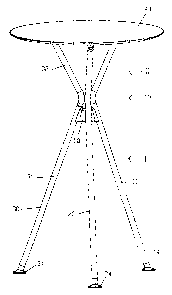
Fig. 1 a table configured as a standing table with three legs, according to
the
invention, in perspective view looking at the table surface;
Fig. 2 the table of Fig. 1 in perspective view looking underneath the table
surface;
Fig. 3 a view of the table with table surface folded down;
Fig. 4 two tables of the same kind, each with table surface folded down,
placed in
a row; and
Fig. 5 a detail view of the connection region of the three legs in cross
section
(plane of the section in the third leg).
WAYS OF IMPLEMENTING THE INVENTION
The standing table shown in the figures has three legs 10, 20 and 30 and a
round table
surface 40. The three legs of similar shape are arranged at a relative angle
of 120
each and run together from the floor upward toward the table surface 40 in a
lower
region I at an angle, first in the shape of a star, and then apart from each
other in an

CA 02606209 2007-10-09
3
upper region II in the shape of a star, so that they end up individually and
with mutual
spacing at the table surface 40. They are only curved in a transitional region
III from the
lower I to the upper region II, otherwise being straight. Just underneath the
curved
transitional region III they are joined together by a connection joint 50 in
the lower
region I.
The two table legs 10 and 20 are joined to the table surface 40 by tilting
links, whose
parts are denoted by 13 and 23 on the legs and by 41 and 42 on the table
surface. The
axes of the tilting links are aligned with each other.
The third table leg 30 is composed of a lower 31 and an upper part 32 in the
lower
region I, so that the upper part 32 comprises the upper region II, the
transitional region,
and also a small portion of the lower region I. The upper part 32 is
detachably joined to
the table surface 40 and can turn relative to the lower part 31.
Due to its turning ability, the upper part 32 can be turned away under the
table surface
40 so that the latter can then be folded down via the tilting links against
the other two
legs 10 and 20, as is represented in Fig. 3. In this position, the upper part
32 of the third
leg 30 rests against the upper region of the second table leg 20 and the table
surface
40 lies against the third leg 30. The table still stands on all three legs.
For the detachable connection of the upper part 32 to the table surface 40, a
head
piece 33 is provided at the end of the upper part 32, with a flat, dishlike
support plate,
and as its counterpart there is a roughly horseshoe-shaped seat 43 in the
table surface
40, provided with an undercut for the projecting edge of the support plate.
Together
with the turning of the upper part 32 for the folding or unfolding of the
table surface 40,
the holding plate of the head piece 33 moves into and out of the undercut
portion of the
seat 43, so that no additional manual steps are required to make or release
the
connection 32. Preferably, the support plate of the head piece 33 is also
easily locked
in the seat 43.
Also preferably the angles at which the three legs 10, 20 and 30 run at a
slant to the
vertical in their lower I and upper region II are chosen such that the table
surface 40
when folded down, as also shown in Fig. 3, is oriented parallel to the lower
part 31 of

CA 02606209 2007-10-09
4
the third leg. This is the case, e.g., when the angle relative to the vertical
is 21 in the
lower region I and 36 in the upper region. The length of the straight segment
in the
lower region I can be 814.4 mm, for example, and 247.9 mm in the upper region
II, with
a radius of 50 mm in the transitional region Ill.
When the table surface 40 is folded down, several tables of the same kind can
be
placed together in space-saving fashion, as shown in Fig. 4 by the example of
two
tables.
Now turning to Fig. 5, the pivoting connection of the lower 31 and upper part
32 of the
third leg 30 shall be described.
Both parts 31 and 32 are tubular and have a round cross section, which
preferably also
applies to the other two legs 10 and 20. All three legs can be made from metal
tubing.
In the upper part 32, a welding round blank 35 is inserted and unable to turn,
e.g., by
welding, and a bolt 36 is anchored in this, also unable to turn, and
projecting downward
into the lower part 31. There, an insert piece 37 is present, accommodating
the bolt 36,
and having a frictional element 38 in a seat, resting against the bolt 36
under elastic
deformation. When the upper part 32 is rotated, the bolt 36 turns in the
insert piece 37
and rubs against the frictional element 38, so that the movement of the upper
part 32 is
dampened by sliding friction relative to the lower part 31. Preferably, the
dampening is
such that the upper part 32 is fixed against rotation under its own weight in
every
position of rotation, but even so it can easily be moved. In this way, the
upper part 32 is
prevented from turning in an uncontrolled manner. A sufficiently large
friction can be
achieved by the use of a material such as polyurethane for the frictional
element 38. In
addition, as also shown in Fig. 5, the bolt 36 can be provided with
circumferential
grooves, into which the elastic material of the frictional element 38 expands,
further
increasing the friction.
The three lets 10, 20 and 30 are screwed together with the connection joint
50. Two
screws 51 used for the third leg can be recognized in Fig. 5, and these screws
at the
same time secure the insert piece 37 in the lower part 31 of the third leg 30.
The
clamping piece 37 is flattened relative to the screws 51, so that it lies
flush against the
inner wall of the lower part 31.

CA 02606209 2007-10-09
The lower ends of the three legs are provided with slide pieces14, 24 and 34.

CA 02606209 2007-10-09
6
LIST OF REFERENCE NUMBERS
first table leg
13 tilting link part
14 slide piece
5 20 second table leg
23 tilting link part
24 slide piece
30 third table leg
31 lower part of third table leg
10 32 upper part of third table leg
33 head piece
34 slide piece
35 welding round blank
36 bolt
37 insert piece
38 frictional element
39 sliding ring
40 table surface
41 tilting link part
42 tilting link part
43 seat
50 connection joint
51 screw
I lower table leg region
II upper table leg region
III transitional region

Representative Drawing
A single figure which represents the drawing illustrating the invention.
Administrative Status

2024-08-01:As part of the Next Generation Patents (NGP) transition, the Canadian Patents Database (CPD) now contains a more detailed Event History, which replicates the Event Log of our new back-office solution.

Please note that "Inactive:" events refers to events no longer in use in our new back-office solution.

For a clearer understanding of the status of the application/patent presented on this page, the site Disclaimer , as well as the definitions for Patent , Event History , Maintenance Fee  and Payment History  should be consulted.

Event History

Description Date
Time Limit for Reversal Expired 2011-10-11
Application Not Reinstated by Deadline 2011-10-11
Deemed Abandoned - Conditions for Grant Determined Not Compliant 2010-10-13
Deemed Abandoned - Failure to Respond to Maintenance Fee Notice 2010-10-12
Notice of Allowance is Issued 2010-04-13
Letter Sent 2010-04-13
Notice of Allowance is Issued 2010-04-13
Inactive: Filing certificate - RFE (English) 2010-04-09
Inactive: Approved for allowance (AFA) 2010-03-16
Inactive: Applicant deleted 2009-08-10
Amendment Received - Voluntary Amendment 2009-07-23
Letter Sent 2008-10-20
Request for Examination Requirements Determined Compliant 2008-08-21
All Requirements for Examination Determined Compliant 2008-08-21
Request for Examination Received 2008-08-21
Application Published (Open to Public Inspection) 2008-04-23
Inactive: Cover page published 2008-04-22
Correct Applicant Request Received 2008-03-17
Inactive: First IPC assigned 2008-02-05
Inactive: IPC assigned 2008-02-05
Inactive: Filing certificate - No RFE (English) 2007-11-23
Letter Sent 2007-11-23
Application Received - Regular National 2007-11-19

Abandonment History

Abandonment Date Reason Reinstatement Date
2010-10-13
2010-10-12

Maintenance Fee

The last payment was received on 2009-10-07

Note : If the full payment has not been received on or before the date indicated, a further fee may be required which may be one of the following

  • the reinstatement fee;
  • the late payment fee; or
  • additional fee to reverse deemed expiry.

Patent fees are adjusted on the 1st of January every year. The amounts above are the current amounts if received by December 31 of the current year.
Please refer to the CIPO Patent Fees web page to see all current fee amounts.

Fee History

Fee Type Anniversary Year Due Date Paid Date
Application fee - standard 2007-10-09
Request for examination - standard 2008-08-21
MF (application, 2nd anniv.) - standard 02 2009-10-09 2009-10-07
Owners on Record

Note: Records showing the ownership history in alphabetical order.

Current Owners on Record
SEDUS STOLL AKTIENGESELLSCHAFT
Past Owners on Record
SIEGFRIED DONNER
TOBIAS WEISSENRIEDER
Past Owners that do not appear in the "Owners on Record" listing will appear in other documentation within the application.
Documents

To view selected files, please enter reCAPTCHA code :


To view images, click a link in the Document Description column. To download the documents, select one or more checkboxes in the first column and then click the "Download Selected in PDF format (Zip Archive)" or the "Download Selected as Single PDF" button.

List of published and non-published patent-specific documents on the CPD .

If you have any difficulty accessing content, you can call the Client Service Centre at 1-866-997-1936 or send them an e-mail at CIPO Client Service Centre.


Document
Description 
Date
(yyyy-mm-dd) 
Number of pages   Size of Image (KB) 
Description 2007-10-08 6 191
Abstract 2007-10-08 1 17
Claims 2007-10-08 2 49
Drawings 2007-10-08 5 67
Representative drawing 2008-03-25 1 4
Description 2009-07-22 7 213
Claims 2009-07-22 2 51
Courtesy - Certificate of registration (related document(s)) 2007-11-22 1 104
Filing Certificate (English) 2007-11-22 1 157
Acknowledgement of Request for Examination 2008-10-19 1 175
Reminder of maintenance fee due 2009-06-09 1 110
Commissioner's Notice - Application Found Allowable 2010-04-12 1 166
Filing Certificate (English) 2010-04-08 1 157
Courtesy - Abandonment Letter (Maintenance Fee) 2010-12-06 1 172
Courtesy - Abandonment Letter (NOA) 2011-01-04 1 165
Correspondence 2008-03-16 3 98