Note: Descriptions are shown in the official language in which they were submitted.
CA 02606225 2007-10-19
WO 2006/112907 PCT/US2006/002614
FLUID DISCHARGE NOZZLE
TECHNICAL FIELD
[0001] The present invention relates to liquid dispensiiig devices having
discharge nozzles and
more particularly to a discharge nozzle having a flow control device.
BACKGROUND OF THE INVENTION
[0002] Liquid filling machines are commonly used to fill containers, bottles
and gable top
cartons with a liquid or other fluid substance, such is as used in the
beverage industry for filling
bottles with, for example, milk, juice, soda, flavored and unflavored waters,
and the like. With
increasing product demands by consumers, beverage packagers have been seeking
ways to
increase the production line speed or rate at which the liquid filling machine
can fill one
container, index the container, and be ready to fill the next container. Some
single-line liquid
filling machines now run at rates, for 1 liter sized containers, approaching
or exceeding about
150 containers per minute. The desire for faster line speeds has been an
ongoing concern of
many beverage packagers.
-[0003] Typical liquid filling machines include a vertically positioned
tubular filling nozzle and
at least one perforated plate at the exit end of the nozzle, which the liquid
passes through just
prior to entering into the container. Messiness, spillage, and waste can occur
if the liquid
continues to flow through the perforated plate of the nozzle while one
container is being moved
from beneath the nozzle and atl empty container is being moved into position
below the nozzle.
Some nozzles utilize the surface tension of the liquid at uniformly sized
apertures in the
perforated plate to assist in cessation of this unintended liquid flow.
SUMMARY OF THE INVENTION
[0004] The present invention provides a fluid dispensing nozzle. The fluid
dispensing nozzle
has a housing. The housing has a fluid flow patll therethrough. A perforated
plate is supported
by the housing within the fluid flow path. The perforated plate having a
plurality of apertures
therethrough wherein there are at least two differently sized apertures. The
at least two
differently sized apertures include a larger size aperture and a smaller size
aperture. The larger
1
CA 02606225 2009-10-07
size aperture is positioned radially inboard of the smaller size aperture. The
larger size aperture can
be centrally located within the perforated plate. A plurality of perforated
plates within the fluid flow
path can also be included. The housing includes a discharge check valve. The
discharge check valve
is capable of creating a vacuum pressure during closing. The smaller size
aperture can include a
plurality of smaller size apertures. The larger size aperture can include a
plurality of larger size
apertures.
[0005] In another embodiment, the fluid dispensing nozzle includes a housing
having a fluid flow
path therethrough. A discharge check valve is within the housing. The
discharge check valve is
capable of creating a vacuum pressure during closing. A perforated plate is
supported by the
housing within the fluid flow path. The perforated plate has a plurality of
apertures therethrough.
The plurality of apertures include at least two differently sized sets of
apertures. The at least two
differently sized sets of apertures include a larger size set of apertures and
a smaller size set of
apertures. The larger size set of apertures are centrally located within the
perforated plate. A
plurality of perforated plates can also be included. At least one of the
perforated plates is formed of
a wire mesh. There is at least one aperture having a shape that is different
from another aperture. At
least one aperture is substantially rectangular. A spacer can be included. The
spacer is positioned to
maintain separation between at least one perforated plate and another
perforated plate.
[0006] In still another embodiment, a fluid discharge nozzle is provided. The
fluid discharge nozzle
includes a nozzle body containing a flow control device within the nozzle
body. The flow control
device includes a check valve and an outlet. The check valve is capable of
creating a vacuum
pressure cycle during closing. The outlet is formed from a perforated plate.
The perforated plate
includes a plurality of apertures. At least one aperture is larger than at
least one other aperture. At
least one larger size aperture is positioned radially inboard of at least one
smaller aperture. A larger
size aperture is centrally located within the perforated plate. A plurality of
perforated plates can be
within the fluid flow path. A spacer can be at the outlet. The spacer can
maintain separation
between the perforated plates.
2
CA 02606225 2009-10-07
In accordance with an aspect of the present invention, there is provided a
fluid dispensing nozzle for
dispensing and cutting off a stream of liquid into a container, the fluid
dispensing nozzle
comprising:
a housing having a fluid flow path therethrough, the housing having an upper
portion
defining an inlet and a lower portion defining an outlet;
a discharge check valve disposed within the housing, between the inlet and the
outlet, the
discharge check valve having an open position allowing a stream of liquid flow
from the inlet to the
outlet, an intermediate position that stops the liquid flow through the
discharge check valve, and a
closed position, wherein the discharge check valve is capable of creating a
vacuum pressure at the
outlet end during closing between the intermediate position and the closed
position; and
at least one perforated plate being supported by the housing and being
positionable and =
confinable within the fluid flow path at the outlet, the at least one
perforated plate having a plurality
of apertures therethrough wherein there are at least two differently sized
apertures including at least
one larger size aperture and at least one smaller size aperture, wherein the
at least one larger size
aperture is positioned radially inboard of the at least one smaller size
aperture, wherein the created
vacuum pressure applied at the at least one larger size aperture increases the
rate of decay of the
liquid stream for dispensing into the container.
In accordance with another aspect of the present invention, there is provided
a fluid dispensing
nozzle for dispensing and cutting off a stream of liquid into a container, the
fluid dispensing nozzle
comprising:
a housing having a fluid flow path therethrough and an outlet;
a discharge check valve within the housing, the discharge check valve having
an open
position allowing a stream of liquid to the outlet, an intermediate position
that stops the liquid flow
through the discharge check valve, and a closed position, wherein the
discharge check valve is
capable of creating a vacuum pressure at the outlet end during closing between
the intermediate
position and the closed position; and
at least one perforated plate being supported by the housing and being
positionable and
confinable within the fluid flow path at the oiztlet, the at least one
perforated plate having a plurality
of apertures therethrough wherein the plurality of apertures include at least
two differently sized
2a
CA 02606225 2009-10-07
sets of apertures including a set of larger size apertures and a set of
smaller size apertures, wherein
the set of larger size apertures is positioned radially inboard of the set of
smaller size apertures,
wherein the created vacuum pressure applied at the set of larger size
apertures increases the rate of
decay of the liquid stream for dispensing into the container.
In accordance with another aspect of the present invention, there is provided
a fluid discharge
nozzle for dispensing and cutting off a stream of liquid into a container, the
fluid dispensing nozzle
comprising:
a nozzle body containing a flow control device within the nozzle body,
the flow control device includes a discharge check valve and an outlet, the
discharge check
valve having an open position allowing liquid flow to the outlet, an
intermediate position that stops
the liquid flow through the discharge check valve and a closed position
wherein the discharge check
valve is capable of creating a vacuum pressure cvcle at the outlet end during
closing between the
intermediate position and the closed position, and the outlet being formed
from at least one
perforated plate wherein the at least one perforated plate includes a
plurality of apertures, wherein at
least one aperture is larger than a size of at least one other aperture,
wherein the at least one larger
size aperture is positioned radially inboard of the at least one other
aperture, and wherein the created
vacuum pressure applied at the at least one larger size aperture increases the
rate of decay of the
liquid stream for dispensing into the container.
In accordance with another aspect of the present invention, the at least one
larger size aperture or
the set of larger size apertures is centrally located within the at least one
perforated plate.
In accordance with another aspect of the present invention, a plurality of
perforated plates within
the fluid flow path is included.
In accordance with another aspect of the present invention, the discharge
check valve is capable of
creating a vacuum pressure during closing.
2b
CA 02606225 2009-10-07
In accordance with another aspect of the present invention, the at least one
smaller size aperture
includes a plurality of smaller size apertures.
In accordance with another aspect of the present invention, the at least one
larger size aperture
includes a plurality of larger size apertures.
In accordance with another aspect of the present invention, there is provided
a fluid dispensing
nozzle further comprising a spacer at the outlet and wherein the spacer
maintains separation
between the at least one perforated plate and another of the plurality of
perforated plates.
In accordance with another aspect of the present invention, a plurality of
perforated plates is
included.
In accordance with another aspect of the present invention, the at least one
of the plurality of
perforated plates is forrried of a wire mesh.
In accordance with another aspect of the present invention, there is at least
one aperture of the set of
larger size apertures having a shape that is different from another aperture.
In accordance with another aspect of the present invention, the at least one
aperture of the set of
larger size apertures is substantially rectangular.
In accordance with another aspect of the present invention, there is provided
a fluid dispensing
nozzle further comprising a spacer and wherein the spacer is positioned to
maintain separation
between the at least one perforated plate and another perforated plate.
BRIEF DESCRIPTION OF' THE DRAWINGS
[0007] While the specification concludes with claims particularly pointing out
and distinctly
claiming the present invention, it is believed that the present invention will
be better understood
2c
CA 02606225 2007-10-19
WO 2006/112907 PCT/US2006/002614
uuin ine ioiiowing description in conjunction with the accompanying drawing
figures, in which
like reference numerals identify like elements, and wherein:
[0008] Figure 1 is a cross-sectional view of an apparatus for dispensing
liquid into containers;
[0009] Figure 2a is a cross-sectional view of the fluid discharge nozzle of
the present invention
shown in the open position;
[0010] Figure 2b is a cross-sectional view of the fluid discharge nozzle of
the present invention
shown in an iiiterinediate position moving from an open position toward a
closed position;
[0011] Figure 2c is a cross-sectional view of the fluid discharge nozzle of
the present invention
shown in the closed position;
[0012] Figure 3a is a partial sectional view of the outlet of Figure 1 shown
in an embodiment
having four perforated plates;
[0013] Figure 3b is a partial sectional view of the outlet of Figure 1 shown
in an alternative
embodiment having two perforated plates;
[0014] Figure 3c is a partial sectional view of the outlet of Figure 1 shown
in an alternative
embodiment having a single perforated plate;
[0015] Figure 4 is a perspective view of a perforated plate of the present
invention;
[0016] Figure 5 is a partial cross-sectional view of the perforated plate of
Figure 4;
[0017] Figure 6 is a graphical illustration of the fluid pressure during the
fill and refill cycle of
the present invention;
[0018] Figure 7 is an illustration of the decay in fluid flow as the liquid
exists the fluid
discharge nozzle when the discharge check valve moves toward the closed
position as illustrated
in Figure 2b;
[0019] Figure 8 is a top plan view of a perforated plate according to the
present invention;
3
CA 02606225 2007-10-19
WO 2006/112907 PCT/US2006/002614
[0020] Figure 9 is a top plan view of an alternative embodiment of a
perforated plate according
to the present invention;
[0021] Figure 10 is a top plan view of anotller alternative embodiment of a
perforated plate
according to the present invention;
[0022] Figure 11 is a top plan view of yet another alternative embodiment of a
perforated plate
according to the present invention; and
[0023] Figure 12 is a top plan view of further still another alternative
embodimeiit of a
perforated plate according to the present invention.
DETAILED DESCRIPTION
[0024] In this detailed description of the present invention, any patent or
non-patent literature
referenced herein and the disclosure contained therein is intended to be and
is hereby
incorporated by reference.
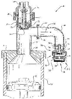
[0025] Referring now to Fig. 1, wherein a liquid dispensing apparatus 10 is
illustrated having a
dispensing nozzle 50 in accordance witli the present invention. Liquid
dispensing apparatus 10
includes an inlet tube 20 that connects that liquid dispensing apparatus 10 to
a fluid reservoir (not
shown).
[0026] Inlet tube 20 is connected to valve holder 28, which contains an inlet
check valve 25.
Inlet check valve 25 is biased such that cover 24 seals against an inlet ring
22 when inlet check
valve 25 is in the closed position. Inlet check valve 25 is biased toward the
closed position by
first spring 26. When inlet check valve 25 is closed, cover 24 seals entry
port 23. Valve holder
28 conilects this inlet check valve 25 to upper end 38 of connector tube 37.
[0027] Connector tube 37 is also attached to cylinder 33 at lower end 39 of
connector tube 37.
Lower end 39 of connector tube 37 is connected to cylinder 33 by cap 35.
Within cylinder 33 is
piston 30. Piston 30 is moveable within cylinder 33. Piston 30 can suck liquid
from reservoir
through inlet check value 25 and when the stroke is reversed Piston 30 can
pressurize any liquid
contained within cylinder 33 in order to expel such liquid from cylinder 33.
4
CA 02606225 2007-10-19
WO 2006/112907 PCT/US2006/002614
[0028] Connector tube 37 is connected to proximate end 42 of discharge tube 40
at flange 46.
Dispensing nozzle 50 is connected to distal end 44 of discharge tube 40
opposite proximate end
42 where connector tube is attached. Upper portion 51 of housing 52 attaches
to distal end 44 of
discharge tube 40 tliereby creating a fluid flow path 59. Fluid flow path 59
passes from inlet
tube 20 through inlet check valve 25 via entry port 23 into coiinector tube 37
and through
discharge tube 40 and out through dispensing nozzle 50. Piston 30 assists in
moving the liquid
from cylinder 33 and connector tube 37 through discharge tube 40 sucli that
the liquid is
intentionally expelled from liquid dispensing apparatus 10 through dispensing
nozzle 50.
[0029] Dispensing nozzle 50 includes a discharge check valve 54 biased by a
second spring 56
against valve body 72 in the closed position. Housing 52 comprises an upper
portion 51 and a
lower portion 53 wherein lower portion 53 confines valve body 72 and positions
discharge check
valve 54. Discharge check valve 54 is spaced away from outlet 60 by displacer
74.
[0030] Now referring to Figure 2a in which is shown that dispensing nozzle 50
includes flow
control device 58 which is made up of two major components, the first
component being
discharge check valve 54 and the second component being outlet 60. Discharge
check valve 54
is positioned within housing 52 adjacent upper portions 51 and outlet 60
spaced away from upper
portion 51 by displacer 74 which is confiiaed within lower portion 53 of
housing 52. Within
valve body 72 is an annular wall 55 for mating with valve head 57 and adjacent
to annular wall
55 in valve body 72, opposite displacer 74, is valve seat 75. In this
embodiment, valve seat 75
has a frusto-conical configuration.
[0031] Discharge check valve 54 is illustrated as being in the open positioii.
The open position
of dispensing check valve 54 is illustrated with fluid flow path 59 passing
between valve head 57
and valve body 72. When valve head 57 is displaced away from inner annular
wall 55 of valve
body 72, an opening is formed creating this fluid flow path 59 through
dispensing nozzle 50. In
the open position of discharge check valve 54, second spring 56 is compressed.
Additionally, in
the open position, valve head 57 of discharge check valve 54 is in close
proximity to displacer
74.
[0032] Referring now to Figure 2b, in which is illustrated dispensing nozzle
50 having
discharge check valve 54, in an intermediate position moving toward the closed
position in
CA 02606225 2007-10-19
WO 2006/112907 PCT/US2006/002614
which valve head 57 is adjacent annular wall 55 and is closely matched to the
inside diameter of
annular wall 55 so that there is minimal clearance (no contact). As discharge
check valve 54
moves toward the closed position, second spring 56 expands. In this
intermediate state, fluid
flow path 59 that passed between valve body 72 and valve head 57 has been
miniznized. As
valve head 57 with 0-ring 61 travels along annular wall 55 toward valve seat
75, a vacuum is
created and suction is applied to fluid that was passing through outlet 60. In
this manner,
discharge clieck valve 54 creates a vacuum pressure cycle within dispensing
nozzle 50. This
suction continues to be applied as 0-ring 61 is compressed and slides across
annular wall 55
toward valve seat 75. It can be seen that annular wall 55 can have an axial
length that is longer
or shorter dependeiit on the duration of time this vacuum pressure cycle or
suction is desired as
0-ring 61 slides against annular wall 55.
[0033] Referring now to Figure 2c in which is illustrated dispensing nozzle 50
having a flow
control device 58 including outlet 60 and discharge check valve 54 wherein
discharge check
valve 54 is in the closed position. Second spring 56 is fully extended and
flow path 59 is closed
as 0-ring 61 on valve head 57 has passed over annular wall 55 and 0-ring 61 is
seated and
sealed against valve seat 75 within valve body 72. In the closed
configuration, valve head 57 is
displaced as far as it is permitted.to travel away from displacer 74 and
intentional flow through
outlet 60 has ceased. Valve seat 75 is sized to sealingly engage against 0-
ring 61 in this closed
position.
[0034] Such a liquid dispensing apparatus 10 having dispensing nozzle 50 with
flow control
device 58 is often used in beverage packaging to fill various items with
liquid including, for
example, bins, bottles, bowls, boxes, buckets, cans, cartons, containers,
cups, jars, jugs, pouches,
and the like. In one embodiment, a gable top filler can be utilized,
including, for example, an
EPE Q-16 high-speed filler available from International Paper Company, of
Stamford,
Connecticut. In another embodiment, a commercially available liquid dispensing
apparatus 10
can be utilized, such as, for example, a Pure-Pak P-S90 standard cross-
section filling machine
available from Elopak a.s., of Spikkestad, Norway. One liquid dispensing
apparatus 10 that may
be used with the present invention is described in U.S. Patent No. 4,958,669
entitled "Device for
Filling Specified Amount of Liquid."
6
CA 02606225 2007-10-19
WO 2006/112907 PCT/US2006/002614
[0035] Turning now to Figure 3a in which is shown a partial sectional view of
outlet 60 of
dispensing nozzle 50. In the embodiment shown, outlet 60 is formed from four
overlying
perforated plates 62. Perforated plates 62 are each spaced apart from one
another by use of outer
spacer 64, which forms an air gap between each perforated plate 62.
Alternatively, outer spacers
64 can be omitted and all perforated plates 62 can ride directly upon each
other eliminating the
air gap. In the present embodiment, perforated plate 62 is confined in outlet
60 and positioned
across fluid flow path 59 while being supported by lower portion 53 of housing
52. These
perforated plates 62 are captured between the radially inwardly extending lip
76 on the eiid of
lower portion 53 and are maintained in position by displacer 74. Each
perforated plate 62 has a
plurality of apertures 65 that extend through perforated plate 62. Apertures
65 extend from
topside 66 of perforated plate 62 through to bottom side 68. Perforated plate
62 is comprised of
filter material 82. 'As used herein, filter material 82 can be any plate,
mesh, screen, sheet, panel,
flap, partition, shield, plug, substrate, or the like whether impermeable or
permeable being made
of metal, plastic, glass, cloth, paper, and the like whether woven, non-woven,
or otherwise, and
whether porous or not. Perforated plate 62 includes plurality of apertures 65
formed in filter
material 82 such that the liquid passing through perforated plate 62 primarily
passes through
apertures 65.
[0036] An alternative embodiment of outlet 60 is shown in Figure 3b. This
embodiment
includes two perforated plates 62 extending across fluid flow path 59.
Perforated plates 62 are
supported by being confined between radially inwardly extending lip 76 and
displacer 74 within
lower portion 53 of housing 52. Outer spacers 64 are placed between first and
second perforated
plates 62 as well as between second perforated plate 62 and displacer 74.
Outer spacer 64
creates an air gap between the two perforated plates 62. Topside 66 of lower
perforated plate 62
is adjacent bottom side 68 of upper perforated plate 62. A plurality of
apertures 65 extend
through from topside 66 to bottom side 68 of both perforated plates 62. The
plurality of
apertures 65 in perforated plate 62 can be aligned with each otlier as
illustrated in Figure 3b or
alternatively apertures 65 in each overlying perforated plate 62 can be
misaligned as illustrated in
Figure 3a. The air gap between adjacent perforated plates 62 can be changed by
increasing or
decreasing height "T" of outer spacer 64.
7
CA 02606225 2007-10-19
WO 2006/112907 PCT/US2006/002614
luu.j /l in another embodiment of outlet 60, a single perforated plate 62 can
be utilized as
shown in Figure 3c. Perforated plate 62 is captured between lip 76 and
displacer 74 at lower
portion 53 of housing 52. Perforated plate 62 is positioned such that it
extends across fluid flow
path 59 in order for the liquid to pass through the plurality of apertures 65
in perforated plate 62.
As illustrated, outer spacer 64 confines perforated plate 62 against lip 76 of
lower portion 53. It
should be understood that outer spacer 64 could be positioned such that
perforated plate 62
directly contacts displacer 74 and outer spacer 64 is placed such that it
directly contacts lip 76
thereby positioning perforated plate 62 to form a recessed outlet 60 within
lower portion 53. In
this manner, bottom side 68 of perforated plate 62 would be spaced away from
lip 76 and topside
66 would be in contact with displacer 74.
[0038} Referring now to Figure 4 wherein a perspective view of outlet 60
formed by a single
perforated plate 62 having an outer spacer 64 around the periphery of
perforated plate 62 is
illustrated. In this view, top side 66 of filter materia182 forming perforated
plate 62 is visible
whereas bottom side 68 cannot be seen. Outer spacer 64 is shown having a
height or thickness
T. A plurality of apertures 65 are shown. Apertures 651ocated in the center
portion or centrally
located within perforated plate 62 are larger than apertures 65 that are
located radially outward
from the center of perforated plate 62. _
[0039] A partial cross-sectional view of filter material 82 having a plurality
of apertures 65
across the center portion of perforated plate 62 is shown in Figure 5, which
is a sectional view
taken at section line 5-5 of Figure 4. In this illustration, topside 66 of
perforated plate 62 and
bottom side 68 along with the plurality of apertures 65 are shown. Each
aperture 65 passes
through filter materia182 of perforated plate 62. At topside 66 each aperture
65 has an entrance
67 and correspondingly at bottom side 68 each aperture 65 has an exit 69. In
one embodiment of
aperture 65, entrance 67 and exit 69 are circular and aperture 65 can form a
right cylinder. In
such an embodiment, smaller aperture 65 has an exit 69 of diameter d and an
entrance 67 of
diameter D, wherein larger aperture 65 has a corresponding diameter D at
entrance 67 and
diameter d at exit 69. It is understood in this illustration that the entrance
67 and exit 69 area
associated witll larger apertures 65 is greater than the entrance 67 and exit
69 area associated
with smaller apertures 65. In an alternative embodiment entrance 67 diameter D
need not be the
same size as exit 69 diameter d, and there could also be an intermediate
diameter spaced between
8
CA 02606225 2007-10-19
WO 2006/112907 PCT/US2006/002614
diameter D and diatneter d which can be the same or a different size. Such an
alternative
embodimeiit can be utilized to increase the surface tension in order to help
prevent unintended
dripping of liquid by increasing the fluid resistance through apertures 65 as
is disclosed in
European Patent Application EPO 784010 B l eiititled "Liquid Charging Nozzle
Plate."
[0040] Turning now to Figure 6, wliich is a theoretical graphical illustration
of the pressure of
the fluid while flowing through the present invention. During the fill cycle,
which is when piston
30 moves toward inlet check valve 25 within cylinder 33, piston 30 causes any
liquid contained
within cylinder 33 to be pushed out of cylinder 33. As fluid is pushed out of
cylinder 33 it enters
connector tube 37 and is blocked from back flowing through inlet tube 20 by
inlet check valve
25 so that the liquid is pressurized and forced through discharge tube 40
toward discharge check
valve 54 within dispensing nozzle 50. This fluid flow path 59 guides the
liquid toward flow
control device 58 and discharge check valve 54 is opened allowing liquid to
flow though outlet
60 passing through perforated plate 62 and out through apertures 65.
[0041] During the fill cycle of a typical liquid dispensing apparatus 10,
there may be three
distinct stages. First is the acceleration stage during which the liquid is
pushed by piston 30 out
of cylinder 33, through discharge tube 40 into dispensing nozzle 50. The slope
of the curve
exhibited in the graph of Figure 6 represents an increase in pressure as the
liquid is started in
motion. Next, optionally, is a constant velocity stage during which the liquid
is being pushed out
dispensing nozzle 50 through apertures 65 in perforated plate 62 by piston 30.
Finally there is a
deceleration stage when piston 30 has stopped pushing the liquid and the
liquid pressure is
decaying.
[0042] After this fill cycle is completed, the refill cycle begins as piston
30 reverses direction
and moves away from inlet check valve 25 within cylinder 33. This movement of
piston 30
generates a vacuum pressure or suction reflected in Figure 6 as a negative
flow rate in gallons
per minute. As the vacuum pressure is generated, discharge check valve 54
moves from an open
position toward a closed position as illustrated in Figure 2b.
[0043] This refill cycle can also be referred to as a vacuum pressure cycle or
"suck-back" cycle
which is further illustrated in Figure 7 wherein arrows 92 and 94 illustrate
the vacuum pressure
or suction. Arrows 94 illustrate the vacuum pressure effect at the central
portion of perforated
9
CA 02606225 2007-10-19
WO 2006/112907 PCT/US2006/002614
plate 62. The centrally positioned vacuum pressure arrows 94 are concentrated
and are a result
of larger sized apertures 65 being centrally positioned in perforated plate
62. This vacuum
pressure 92, 94 applies a suction force to stream of liquid 80, which is
passing through perforated
plate 62, in a direction opposed to the gravitational force illustrated by
arrows 96.
[0044] Ordinarily the stream of liquid 80 coming out of outlet 60 through
perforated plate 62 is
shaped as an inverted cone being larger on bottom side 68 of perforated plate
62 and growing
smaller as gravity 96 accelerates the liquid away from perforated plate 62. As
the fill cycle ends
the inverted cone shape stream of liquid 80 grows smaller and thinner until
finally all flow is cut
off.
[0045] Since the intentional liquid flow is cut off when discharge check valve
54 moves into
its intermediate position toward closing (as illustrated in Figure 2b), there
is no additional liquid
added to stream of liquid 80. Vacuum pressure 92, 94 is counteracting the
force of gravity 96
upon stream of liquid 80. Therein, stream of liquid 80 is a decaying flow and
this stream of
liquid 80 diminishes while it is still in contact with bottom side 68 of
perforated plate 62. The
vacuum suction applied to topside 66 of perforated plate 62 and especially at
larger apertures 65
that are centrally located in perforated plate 62 enables the greatest amount
of vacuum pressure
94 to be applied to the center portion of stream of liquid 80. When this
suction is initiated by
piston 30 reversing direction within cylinder 33, this vacuum pressure 94
increases the rate at
which stream of liquid 80 decays causing stream of liquid 80 to disconnect
faster from bottom
side 68 of perforated plate 62 in the form of a droplet of liquid. The shorter
the decay time, the
faster a filled container can be moved from beneath dispensing nozzle 50 and
the quicker an
empty container can be moved into position for filling by liquid dispensing
apparatus 10. This
vacuum pressure cycle along with large apertures 65 located in the center of
perforated plate 62
enables significantly increased rates of speed at which containers can be
changed or moved
during the filling operation without inadvertently spilling any of the liquid
outside of the
container. Capillary action in apertures 65 of perforated plate 62 allows
outlet 60 of dispensing
nozzle 50 to hold the liquid without any flow or drips occurring after the
fluid flow has been shut
off.
CA 02606225 2007-10-19
WO 2006/112907 PCT/US2006/002614
[0046] The present invention helps to conceiitrate the greatest vacuum force
on the decaying
portion of stream of liquid 80 right in the center of perforated plate 62. By
adding larger
apertures 65 or a coarser mesh section in the center of perforated plate 62
where stream of liquid
80 below dispensing nozzle 50 is decaying, the vacuum pressure 94 will have
greatest effect.
When the liquid is no longer being pushed out discharge check valve 54 and
discharge check
valve 54 begins to close is when the vacuum pressure cycle begins. During this
vacuum pressure
cycle, liquid can also be sucked, by the vacuum pressure 94, from between
perforated plates 62
when there are multiple perforated plates 62 utilized at outlet 60 and from
below the discharge
check valve 54 since a backflow is caused by the vacuum pressure 94 through
perforated plates
62. There may still be an inverted cone of stream of liquid 80 hanging below
perforated plate 62
but this vacuum pressure 94 helps to draw some of this liquid back up into
dispensing nozzle 50
speeding the decay of stream of liquid 80.
[0047] Various perforated plates 62 can be utilized in the present invention
having a plurality
of apertures 65 extending there through including the embodiment of a
perforated plate 62 as
shown in Figure 8. This top plan view of perforated plate 62 has a periphery
that is circular
wherein apertures 65 extend through filter material 82 and apertures 65 are
somewhat
rectangular in shape. In a central portion of perforated plate 62 arQ located
larger apertures 65
surrounded by a plurality of smaller apertures 65. A representative perforated
plate 62 of this
nature could be constructed from filter materia182 in the form of a wire mesh.
[0048] An alternative embodiment of a perforated plate 62 is shown in Figure
9. Perforated
plate 62 having larger apertures 651ocated in the central portion with smaller
apertures 65
surrounding that central portion and extending through filter material 82 is
illustrated having an
outer spacer 64 at the perimeter of perforated plate 62 and inner spacer 63 is
located at the
perimeter of larger apertures 65 located in the center of per.forated plate
62. In this embodiment
the thickness or height of outer spacer 64 may be the same as inner spacer 63
to provide a central
supporting structure wllen perforated plates 62 are stacked together in a
multiple perforated plate
62 configuration at outlet 60. An air gap formed between the multiple
perforated plates 62 is
maintained by outer spacer 64 and inner spacer 63. Such a configuration is
helpful when there
are thick or high viscosity liquids being dispensed through dispensing nozzle
50 and passing
through outlet 60 through plurality of apertures 65 in perforated plate 62.
11
CA 02606225 2007-10-19
WO 2006/112907 PCT/US2006/002614
100491 Another embodiment of perforated plate 62 is shown in Figure 10. In
this embodiment,
perforated plate 62 has a single large aperture 65 in the center of perforated
plate 62. This large
aperture 65 extends through filter material 82 and is surrounded by a
plurality of smaller
apertures 65 in perforated plate 62.
[0050] Referring now to Figure 11, yet another embodiment of perforated plate
62 is
illustrated. Perforated plate 62 is shown as being constructed from filter
material 82 in the form
of a generally circular plate with apertures 65 extending through filter
material 82. Apertures 65
are generally circular in shape and there are larger apertures 65 in the
center of perforated plate
62 surrounding by a plurality of smaller circular apertures 65. While
perforated plate 62 is
shown being substantially circular, a variety of other shapes whether regular
or irregular can be
utilized in the construction and arrangement of fluid flow path 59 and outlet
60.
[0051] The embodiment illustrated in Figure 12 has three different sizes of
apertures 65 in
three different regions of filter material 82 in perforated plate 62. In
particular, this embodiment
of perforated plate 62 has large hexagonal apertures 871ocated in the center
region of perforated
plate 62 with a plurality of medium sized circular apertures 86 surrounding
the large hexagonal
apertures 87. Surrounding medium size aperture 86 there is a plurality of
smaller apertures 85
that extend through perforated plate 62. Moreover, such apertures 65 could
also be rectangular,
triangular, octagonal, or any other desirable shape. The shape of apertures 65
may be selected
for desirable fluid flow characteristics for the particular dispensing nozzle
50 as the liquid passes
through perforated plate 62. All of these and more alternative configurations
of perforated plate
62 can be utilized as a portion of flow control device 58 to modify flow
control device 58 at
outlet 60.
[0052] Many other alternative embodiments and configurations may be apparent
to those of
ordinary skill in the art. For example, dispensing nozzle 50 could be
constructed with a flapper-
type discharge check valve 54. In addition to beverages and other flowable
food substances,
liquid dispensing apparatus 10 of the present invention can be used for non-
food grade flowable
substances and liquids such as beauty care products, healthcare products,
pharmaceuticals,
lubricants, fuels, additives, solvents, pesticides, herbicides and any other
liquid or fluid
substances. Additionally, various sizes and shapes of apertures can be
utilized to obtain an
12
CA 02606225 2007-10-19
WO 2006/112907 PCT/US2006/002614
appropriate vacuum pressure cycle to counteract the force of gravity on stream
of liquid 80 in
order to modify the intended flow of liquid or to shut off the unintended flow
of liquid and avoid
spillage as filled containers are moved away from outlet 60 of dispensing
nozzle 50 in order for
liquid dispensing apparatus 10 to charge or fill otlier containers. The
various aperture 65 shapes
can be foq'ned using commonly known methods and processes such as through the
use of laser,
water jet, and conventional drilling or through the use of punch press,
weaving, or other
processes.
[0053] Whetller there are multiple perforated plates 62 with various sized
apertures 65, or
multiple perforated plates 62 with variations in mesh sizing in certain areas,
or a coinbination of
both. Perforated plates 62 with a plurality of apertures 65 having larger
apertures 65 in the
center portion can be intermixed with mesh screens and perforate plates having
uiliform aperture
65 sizes therein. The size and shape of apertures 65 can be varied as a
function of the liquid
viscosity, fluid surface tension, flow speed of the liquid being discharged,
the capillary action of
perforated plates 62, and the ability of the liquid to resist air being drawn
back up into outlet 60.
[0054] While a number of particular embodiments of the present invention have
been
described and illustrated, it will be understood to those skilled in the art
that various additional
changes and modifications can be made without departing from the spirit and
scope of the
present invention. Accordingly, it is intended to cover, in the appended
claims all such changes
and modifications that are within the scope of this invention.
13