Note: Descriptions are shown in the official language in which they were submitted.
CA 02606350 2007-10-09
UNIVERSAL LINKAGE ASSEMBLY FOR A POWER MACHINE
BACKGROUND OF THE INVENTION
Power machines, such as skid steer loaders compact
tool carries, diggers or other power machines are used
for a wide variety of applications including for example
construction, landscaping and other applications.
Typically power machines are driven or operated using
various hand levers, joysticks or other controls. For
example, power machines can include joysticks to drive,
steer and/or operate or control different attachments or
implements. Joysticks can have different control
patterns for operating the machine. Standard control
patterns include for example, ISO pattern or H-control
pattern. Different users can prefer different
operating patterns depending upon user preference or
training and prefer mechanical control systems over
electric control systems. The present invention
addresses these and other issues and provides advantage
over prior operating control systems for a power machine
or vehicle.
SUMMARY OF THE INVENTION
The present invention relates to a universal
linkage assembly that is adaptable for different control
patterns or configurations. For example in illustrated
embodiments, the linkage assembly includes a first
control interface connectable to a first joystick to
operate one of a left or right drive motor or other
CA 02606350 2007-10-09
-2-
function and a second control interface connectable to
either the first joystick or a second joystick to
operate the other of the left or right drive motor or
other function depending upon the control pattern
desired. The invention as disclosed provides advantages
over prior linkage assemblies that could not be easily
adapted for different control patterns.
BRIEF DESCRIPTION OF THE DRAWINGS
FIG. 1 is a side view of an embodiment of a power
machine in which a universal linkage assembly is used.
FIG. 2 is a schematic illustration of illustrative
operating components or functions of the power machine
of FIG. 1.
FIGS. 3-4 are schematic illustrations of operating
control patterns for left and right joysticks for a
power machine or vehicle of the type illustrated in FIG.
l.
FIG. 5 is a schematic illustration of an operating
control pattern for left and right joysticks and left
and right foot pedals for a power machine or vehicle of
the type illustrated in FIG. 1.
FIGS. 6-8 illustrate an embodiment of a universal
linkage assembly adapted to implement a control pattern
using right and left joysticks and right and left foot
pedals.
CA 02606350 2007-10-09
-3-
FIGS. 9-11 illustrate the embodiment of the
universal linkage assembly of FIGS. 6-8 adapted to
implement the control pattern illustrated in FIG. 4.
FIGS. 12-14 illustrate the embodiment of the
universal linkage assembly of FIGS. 6-8 adapted to
implement the control pattern illustrated in FIG. 3.
DETAILED DESCRIPTION OF ILLUSTRATIVE EMBODIMENTS
FIG. 1 illustrates an embodiment of a power
machine or vehicle 100 in which embodiments of the
universal linkage disclosed herein can be incorporated
or used. As shown, the illustrated power machine
includes a body 104 that is supported relative to a
frame (not shown). Wheels 106 are coupled to the frame
so that the power machine 100 or vehicle can be driven
over the ground during use. Application, however, of the
present invention is not limited to a wheeled vehicle or
loader as shown. For example, the present invention has
application for a power machine, which moves along a
track instead of wheels.
As shown in FIG. 1, the illustrated power machine
100 includes a boom assembly 110 that is used to raise,
lower or position a work implement or attachment 112,
(which in the illustrated embodiment is a bucket) . The
boom assembly 110 includes lift arms 120 (only one of
which is shown in FIG. 1) . Lift arms 120 are pivotally
coupled to the body 104 of the machine to raise and
lower the attachment 112. Hydraulic cylinders or
CA 02606350 2007-10-09
-4-
actuators 124 (only one shown in FIG. 1) are coupled to
the body 104 and lift arms 120 to raise and lower the
lift arms 120. In FIG. 1, the boom assembly 110 is
shown in the lowered position and shown in the raised
position in phantom.
The attachment or implement 112 is rotationally
coupled to the lift arms 120 so that an orientation of
the implement 112 can be adjusted relative to the lift
arms 120. Implement 112 is rotationally adjusted or
tilted via a tilt cylinder (not shown in FIG. 1). The
tilt cylinder is extended and retracted to adjust the
orientation or tilt (e.g. curl or dump position) of the
attachment or implement 112.
Although FIG. 1 illustrates a bucket attachment or
implement, application is not limited to a bucket and
other implements can be attached to the lift arms 120 or
machine depending upon the particular work application.
For example, lift arms 120 of the power machine can
support a spade or other implement.
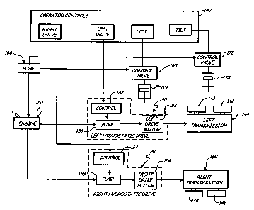
As schematically shown in the embodiment
illustrated in FIG. 2, the power machine is driven and
steered through a hydrostatic drive assembly or system
which transmits power to wheels 106 of the power
machine. In the illustrated embodiment shown, the
hydrostatic drive assembly includes a left hydrostatic
drive 140 that transmits torque or power to left wheels
142 (illustrated schematically) through a left drive
transmission 144 and a right hydrostatic drive 146 that
CA 02606350 2007-10-09
-5-
transmits torque or power to the right wheels 148
through the right drive transmission 150.
The left and right drives 140, 146 include left
and right hydrostatic drive motors 152, 154. Fluid is
supplied to the left and right drive motors 152, 154
from left and right pumps 156, 158 operated via engine
160. In the illustrated embodiment, the hydrostatic
drives 140, 142 include a variable displacement pumps
156, 158 operable via controls (or swashplate) 162, 164.
Control 162 controls the magnitude and direction of
fluid flow from pump 156 to the left drive motor 154 to
operate the left wheels and control (or swashplate) 164
controls the magnitude and direction of fluid flow to
the right drive motor 152 to operate the right wheels
148. Fluid is provided to both left and right drive
motors 152, 154 to power left and right wheels for
forward and aft motion. Steer motion is imparted to the
power machine by providing fluid flow to one of the left
or right drive motors 152, 154 to provide a skid steer
motion to the power machine.
As previously described, the lift function is
operated through hydraulic actuator or cylinder 124.
Hydraulic fluid is supplied from pump 166 powered via
engine 160 to the lift cylinder 124 through operation of
control or servo valve 168 as schematically shown in
FIG. 2. Similarly fluid is supplied from pump 166 to a
tilt cylinder 170 through operation of servo or control
CA 02606350 2007-10-09
-6-
valve 172 to adjust an orientation of an implement or
attachment.
The direction and magnitude of flow to the left
and right drive motors 152, 156 and lift and tilt
cylinders 124, 170 is controlled based upon input from
operator controls 180 of the power machine. Operator
controls 180 include various levers, pedal, and/or
joysticks that allow the user to move the power machine
or vehicle in a forward direction, reverse direction
and/or steer the machine or vehicle as well as control
or operate implements or attachments of the power
machine. In the illustrated embodiment, operating
controls 180 include left and right drive functions and
lift and tilt control functions that operate controls
and/or valves 162, 164, 168, 172 to supply hydraulic
fluid flow to the various actuators or drive motors.
Alternate hydrostatic drive assemblies include a
fixed displacement pumps and variable displacement
motors or fixed displacement pumps and motors where the
magnitude and direction of fluid flow is regulated
through a control valve. Alternate embodiments of the
present invention can be implemented for alternate
hydrostatic drive assemblies and application is not
limited to a variable displacement pump and fixed
displacement motor as described.
Different power machines have different operator
control designs or patterns. FIG. 3 illustrates one
control pattern using left and right joysticks 190, 192
CA 02606350 2007-10-09
-7-
configured to drive, steer and activate lift and tilt
functions of the power machine. As shown, both joystick
190, 192 are operable in a forward direction 194,
reverse direction 196 and transverse direction 197.
The left joystick 190, in the embodiment
illustrated in FIG. 3, is configured for drive and steer
functions and the right joystick 192 is configured to
control lift and tilt functions for an attachment or
implement. Movement of the left joystick 190 in the
forward and aft directions 194, 196 moves the machine in
forward and reverse directions, respectively and
movement of the left joystick 190 in the transverse
direction 197 provides left and right steer motion
through operation of the left and right drive motors
152, 154.
The right joystick 192 is arranged so that forward
and aft movement raises and lowers the lift arms 120 and
transverse movement in the traverse direction 197
adjusts the tilt of the attachment or bucket through the
tilt cylinder or cylinders 170.
FIG. 4 illustrates another operator control design
or pattern. The illustrated pattern is an H control
pattern where both left and right joysticks 190, 192 are
used to cooperatively drive and steer the power machine
or vehicle. As shown, movement of the left joystick 190
in the forward and aft directions 194, 196 controls the
left drive motor 152 and forward and aft movement of the
right joystick 192 controls right drive motor 154.
CA 02606350 2007-10-09
-g-
Thus, both joysticks 190, 192 are moved forward
and aft to impart forward and reverse motion to the
power machine. Steer input is provided by forward or
aft movement of one or either of the joysticks 190, 192
to impart drive or movement to one side (wheels 142) or
the other side (wheels 148) of the power machine
depending upon the steer direction. Transverse movement
of the left joystick 190 in the traverse direction 197
is used to raise and lower the lift arms 120 and
transverse movement of the right joystick 192 in the
traverse direction 197 is used to control or adjust tilt
of the attachment or bucket 112 as previously described.
FIG. 5 illustrates another operator control
pattern for left and right joysticks 190, 192 and left
and right foot pedals 198, 199. As shown, movement of
joysticks 190, 192 in the forward and aft directions
194, 196 cooperatively drives and steers the power
machine as previously described for the operating
control pattern illustrated in FIG. 4. In the embodiment
shown in FIG. 5, lift and tilt functions are controlled
via the left and right foot pedals 198, 199.
In particular, depression of left foot pedal 198
as illustrated by arrow 198-1 lowers the lift arms 120
or implement and depression of the right foot pedal 199
as illustrated by arrow 199-1 dumps the bucket or other
implement. Release of the left foot pedal 198 as
illustrated by arrow 198-2 raises the lift arms 120 or
implement and release of the right foot pedal 199 as
CA 02606350 2007-10-09
-9-
illustrated by arrow 199-2 curls the bucket or other
implement.
Different control patterns require different
linkages to connect the operator controls 180 to various
machine controls or valves (e.g. 162, 164, 168, 172) to
implement the selected function or functions. For
example, in FIG. 3 drive and steer functions are
controlled through the left joystick 190 while in FIG.
4, both joysticks 190, 192 are used to cooperatively
drive and steer the power machine or vehicle. FIGS. 5-13
illustrate a universal linkage assembly 200 that is
adaptable for different operator control designs or
control patterns, such as the patterns illustrated in
FIGS. 3-5.
FIGS. 6-8 illustrate an embodiment of the
universal linkage assembly 200 adapted to interface with
joysticks 190, 192 and foot pedals 198, 199 for
operating drive, steer, lift and tilt functions of a
power machine. As shown, the universal linkage assembly
200 includes a drive interface 210 for drive and steer
functions and a power interface 212 for lift and tilt
functions. In the embodiment shown, the universal drive
interface 210 includes a drive shaft having an inner
cylindrical body 214 and an outer cylindrical sleeve 216
rotatable about the inner cylindrical body 214. Pumps
154 and 156 are formed in block 218.
As shown, the outer cylindrical sleeve 216 is
coupled to the left control (or swashplate) 162 to
CA 02606350 2007-10-09
-10-
control the magnitude and direction of flow of hydraulic
fluid from pump 156 to the left drive motor 152 through
link rod 220 attached to the outer cylindrical sleeve
216 at link attachment 222. The inner cylindrical body
214 is coupled to the control 164 to control the
direction and magnitude of flow of hydraulic fluid from
pump 158 to the right drive motor 154 through link rod
228 attached to the inner cylindrical body 214 at link
attachment 230. Rotation of the inner cylindrical body
214 linearly moves link rod 228 to adjust control 164 to
control the magnitude and direction of flow of hydraulic
fluid from pump 158 and rotation of the outer
cylindrical sleeve 216 linearly moves link rod 220 to
adjust control 162 to control the direction and
magnitude of hydraulic fluid flowfrom pump 156.
Left and right joysticks 190, 192 are coupled to
the inner cylindrical body 214 and outer cylindrical
sleeve 216 respectively to rotate the inner cylindrical
body 214 and outer cylindrical sleeve 216 to operate
controls 162, 164 as previously described. In the
embodiment shown, joysticks 190, 192 are rotationally
coupled to posts 240 fixed to the frame of the power
machine to move in the forward and aft directions 194,
196.
Left joystick 190 is coupled to the outer
cylindrical sleeve 216 through link rod 242 and drive
attachment 244 and right joystick 192 is coupled to the
inner cylindrical body 214 through link rod 246 and
CA 02606350 2007-10-09
-11-
drive attachment 248. Forward and aft movement of the
joysticks in the forward and reverse directions 194, 196
linearly moves rods 242, 246 to rotate the outer
cylindrical sleeve 216 and the inner cylindrical body
214, respectively to control left and right pumps 156,
158 as previously described.
Similarly, in the illustrated embodiment, the
power interface includes a power shaft having an inner
cylindrical body 250 rotationally coupled to the frame
and an outer cylindrical sleeve 252 rotatable about the
inner cylindrical body 250 to operate lift and tilt
functions of the power machine. For example in the
illustrated embodiment, the inner cylindrical body 250
is coupled to the lift valve at attachment 254 to raise
and lower the boom or arms of the power machine through
a linkage (not shown) via rotation of the inner
cylindrical body 250. The outer cylindrical sleeve 252
is coupled to the tilt valve 168 at attachment 256 to
adjust tilt through linkage (not shown) via rotation of
the outer cylindrical sleeve 252.
In the illustrated embodiment, the inner
cylindrical body 250 and the outer cylindrical sleeve
252 are rotated or operated via the left and right foot
pedals 198, 199. In particular, as shown, left pedal
198 is connected to the inner cylindrical body 250
through attachment 260 and the right foot pedal 199 is
connected to the outer cylindrical sleeve 252 through
attachment 262.
CA 02606350 2007-10-09
-12-
FIG. 8 is a side view of left joystick 190
illustrating an interconnect between joystick 190 and
link rod 242 connected to outer cylindrical sleeve 216
of the drive shaft. As shown, left joystick 190 is
coupled to the link rod 242 through interconnect block
270. Interconnect block 270 is rotationally coupled to
post 240 to rotate about axis 272. The interconnect
block 270 rotates about axis 272 via forward and aft
movement of joystick 190. As shown, link rod 242 is
coupled to the interconnect block 270 at a location
spaced from axis 272. Thus, forward and aft movement of
joystick 190 rotates block 270 to linearly move rod 242
to rotate the outer cylindrical sleeve 216 in a
clockwise or counterclockwise direction to control fluid
flow to hydraulic motor 152 via pump 156 through link
rod 220 and control 162.
Similarly, joystick 192 (not shown in FIG. 7) is
coupled to link rod 246 through an interconnect block
270 rotationally coupled to post 240 as previously
described to rotate the inner cylindrical body 214 via
forward and aft movement of the right joystick 192.
In the control pattern shown, both joysticks 190,
192 are moved in a forward direction for forward drive
and aft direction for reverse drive. To steer,
joysticks 190, 192 are moved independently to impart a
differential motion to the left and right wheels 142,
148. Thus, as described and as shown in FIGS. 6-8,
movement of joysticks 190, 192 in the forward and aft
CA 02606350 2007-10-09
-13-
directions rotates the inner cylindrical body 214 and
outer cylindrical sleeve 216 to drive and steer the
power machine through linkages or link rods 220 and 228.
FIGS. 9-11 illustrate the embodiment of the
universal linkage assembly 200 previously illustrated in
FIGS. 6-8 adapted to provide an interface for an
alternate control pattern similar to that illustrated in
FIG. 4. As previously described, rotation of the outer
cylindrical sleeve 216 and inner cylindrical sleeve 214
operates controls 162, 164 to operate the left and right
drive motors 152, 154 (not shown) and rotation of the
inner cylindrical body 250 and outer cylindrical body
252 operate lift and tilt functions. Similar to the
embodiment illustrated in FIGS. 6-8, the outer
cylindrical sleeve 216 and inner cylindrical body 214
are rotated through joysticks 190, 192 through link rods
242, 246.
Instead of foot pedals 198, 199 however, in the
illustrated control pattern, the inner cylindrical body
250 and outer cylindrical sleeve 252 of the power shaft
are also rotated or controlled through joysticks 190,
192. As shown, the left 190 joystick is coupled to the
inner cylindrical body 250 through link rod 280 at
attachment 282 and the right joystick 192 is coupled to
the outer cylindrical sleeve 252 through link rod 284 at
attachment 286. Transverse movement of the joysticks
190, 192 in the transverse direction 197 linearly moves
link rods 280, 284 to rotate the inner cylindrical body
CA 02606350 2007-10-09
-14-
250 and outer cylindrical sleeve 252 to operate lift and
tilt functions or other functions of the machine.
FIG. 10 is a side view of the right joystick 192
illustrating interface between joystick 192 and link rod
246 for drive and link rod 284 for tilt. As shown in
FIG. 10, joystick 192 is coupled to interconnect block
270 through a floating bracket 290. Bracket 290 is
rotatably coupled to block 270 to rotate about axis 292.
Similarly, joystick 190 (not shown in FIG. 10) is
coupled to block 270 through floating bracket 290.
Transverse movement of joysticks 190, 192 imparts
rotation to the floating bracket 290 about axis 292. As
previously described, drive rods 242, 246 are aligned
with axis 292 and are coupled to block 270 or
interconnect at a location spaced from axis 272 so that
rotation about axis 272 linearly moves link rods 242,
246 (only rod 246 is shown in FIG. 10) to control
hydraulic fluid flow through rotation of the inner
cylindrical body 214 and outer cylindrical sleeve 216 of
the drive shaft.
Rods 280, 284 (only rod 284 is shown in FIG. 10)
are coupled to the joystick interface in alignment with
axis 272 at a location spaced from axis 292 as shown in
FIG. 11. Movement of joysticks 190, 192 in the
transverse direction 197 thus rotates the interconnect
or bracket 290 about axis 292 to linearly move rods 280,
284 to rotate the inner cylindrical body 250 and outer
CA 02606350 2007-10-09
-15-
cylindrical sleeve 252 of the power shaft for operating
lift and tilt functions as previously described.
Thus as illustrated in FIGS. 9-11, movement of the
joysticks 190, 192 in the forward and aft directions
194, 196 rotates the interconnect about axis 272, to
linearly actuate rods 242, 246 to rotate one or both of
the inner cylindrical body 214 and/or outer cylindrical
sleeve 216 to drive and/or steer the power machine.
Movement of the joysticks 190, 192 in the transverse
direction 197 rotates the interconnect about axis 292 to
linearly actuate rods 280, 284 to rotate one or both of
the inner cylindrical body 250 or outer cylindrical
sleeve 252 to control lift and tilt functions.
FIGS. 12-14 illustrate the universal linkage
assembly of FIGS. 6-11 adapted to provide an interface
for a pattern similar to that shown in FIG. 3 where the
drive and steer functions are controlled through the
left joystick 190 and lift and tilt functions are
controlled through the right joystick 192. As shown in
FIG. 11, the inner cylindrical body 214 and outer
cylindrical sleeve 216 of the drive shaft are rotated
through link rods 242, 246 coupled to the left joystick
190 and the inner cylindrical body 250 and outer
cylindrical sleeve 252 of the power shaft are rotated
through link rods 280, 284 coupled to the right joystick
192.
In the universal linkage shown in FIGS. 6-14, a
length of the inner cylindrical bodies 214, 250 is
CA 02606350 2007-10-09
-16-
longer than the outer cylindrical sleeves 216, 252 to
form a left portion extending beyond an end of the
cylindrical sleeve 216, 252 and a right portion
extending beyond the other end of the outer cylindrical
sleeve 216, 252 to provide a link attachment to the
inner cylindrical body 214, 250 on either the left side
or right side to interface with either the right or left
joysticks 190, 192.
In particular, the link rod 246 can be connected
to the right portion of the inner cylindrical body 214
and rotated by the right joystick 192 as shown in FIG. 6
or connected to the left portion of the inner
cylindrical body 214 and rotated by the left joystick
190 as illustrated in FIG. 12. As shown, the outer
cylindrical sleeve 216 includes a left attachment to
connect to the left joystick 190 through rod 242 to
control the left drive motor 152. Rod 246 coupled to the
inner cylindrical body 214 can be connected to either
the left joystick 190 so that both the left and right
drive motors 152, 154 are operated through the same
joystick or alternatively, rod 246 can be connected to
right joystick 192 so that left and right drive 152, 154
are controlled through separate joysticks for the
control pattern illustrated in FIG. 4.
Similarly, rod 280 can be connected to the left
portion of the inner cylindrical body 250 and rotated by
the left joystick 190 as shown in FIG. 9 or connected to
the right portion of the inner cylindrical body 250 and
CA 02606350 2007-10-09
-17-
rotated by the right joystick 192 as illustrated in FIG.
12. As shown, the outer cylindrical sleeve 252 includes
a right attachment to connect to the right joystick 192
through rod 284 to control tilt (in contrast to the left
joystick 190 that is coupled to the outer cylindrical
sleeve 216 of the drive shaft). Rod 280 is coupleable to
either a left or right attachment of the inner
cylindrical body 250 to connect to either the right
joystick 192 so that both lift and tilt are operated
through the same joystick as illustrated in FIG. 3 or to
connect to the left joystick 190 so that the lift and
tilt are operated via separate joysticks 190, 192 as
illustrated in FIG. 4.
Although in FIG. 12, both rods 242, 246 are
coupled to the left joystick 190 and rods 280, 284 are
coupled to the right joystick 192, application is not
limited to the illustrated embodiment and alternatively
rods 242, 246 can be connected to the right joystick 192
and rods 280, 282 connected to the left joystick 190.
As cooperatively shown in FIG. 12, rods 242, 246
are connected to the interconnect forward of the axis
272 so that forward and aft movement in direction 194,
196 of joystick 190 linearly moves rods 242, 246 to
rotate both the inner cylindrical body 214 and outer
cylindrical sleeve 216 to provide forward and aft motion
to the power machine or vehicle. As shown in FIG. 12,
rods 242, 246 are coupled to the interconnect at
locations spaced from axis 292 so that transverse
CA 02606350 2007-10-09
-18-
movement of joystick 190 in the direction 197 rotates
the bracket 290 to actuate one of the rods 242, 246 to
impart a steer motion through rotation of the inner
cylindrical body 214 or outer cylindrical sleeve 216.
As shown in FIG. 13, rods 280, 284 connected to
the inner cylindrical body 250 and outer cylindrical
sleeve 252 of the power shaft are coupled to the right
joystick 192 for lift and tilt control. Rod 280 is
connected to the interconnect at a location spaced from
axis 272 (not shown in FIG. 13) so that forward/aft
motion of the joystick 192 rotates the linkage block 270
about axis 272 to rotate the inner cylindrical body 250
to control lift.
As shown in FIG. 14, rod 284 is coupled to the
interconnect spaced from rotation axis 292 so that
transverse movement of the joystick 192 imparts linear
movement to rod 284 via rotation of the interconnect
about axis 292 to rotate the outer cylindrical sleeve
252 to control tilt. Alternatively, the left joystick
190 can be adapted to control lift and tilt function and
the right joystick 192 can be adapted to control drive
and steer functions and application is not limited to
the particular connections shown.
Although the present invention has been described
with reference to preferred embodiments, workers skilled
in the art will recognize that changes may be made in
form and detail without departing from the spirit and
scope of the invention.