Language selection

Search

Patent 2606360 Summary

Third-party information liability

Some of the information on this Web page has been provided by external sources. The Government of Canada is not responsible for the accuracy, reliability or currency of the information supplied by external sources. Users wishing to rely upon this information should consult directly with the source of the information. Content provided by external sources is not subject to official languages, privacy and accessibility requirements.

Claims and Abstract availability

Any discrepancies in the text and image of the Claims and Abstract are due to differing posting times. Text of the Claims and Abstract are posted:

  • At the time the application is open to public inspection;
  • At the time of issue of the patent (grant).
(12) Patent Application: (11) CA 2606360
(54) English Title: BACK REST FOR A CHAIR
(54) French Title: DOSSIER DE CHAISE
Status: Deemed Abandoned and Beyond the Period of Reinstatement - Pending Response to Notice of Disregarded Communication
Bibliographic Data
(51) International Patent Classification (IPC):
  • A47C 07/40 (2006.01)
(72) Inventors :
  • MAIER, PETER (Germany)
  • FISCHER, HARRY (Germany)
(73) Owners :
  • SEDUS STOLL AKTIENGESELLSCHAFT
(71) Applicants :
  • SEDUS STOLL AKTIENGESELLSCHAFT (Germany)
(74) Agent: MARKS & CLERK
(74) Associate agent:
(45) Issued:
(22) Filed Date: 2007-10-09
(41) Open to Public Inspection: 2008-04-18
Examination requested: 2008-10-10
Availability of licence: N/A
Dedicated to the Public: N/A
(25) Language of filing: English

Patent Cooperation Treaty (PCT): No

(30) Application Priority Data:
Application No. Country/Territory Date
102006 049 677.9 (Germany) 2006-10-18

Abstracts

English Abstract


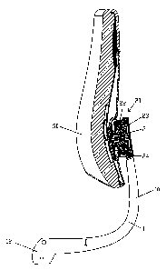
For a back rest for a chair with a back support (10) and a back surface (30)
secured to
this and able to swivel about a two-axis joint (20), wherein the joint (20)
has a joint plate
(21) connected to the back surface, an element made of an elastic material
that
supports the joint in a ground position, and a chamber 24 to accommodate the
elastic
element, connected to the back support (10), the invention specifies that the
joint plate
(21) is arranged in the receiving chamber (24) between two elements (22, 23)
made
from an elastic material, holding the joint in a ground position and each
being supported
against the receiving chamber (24), and it can swivel about the two swivel
axes. When
the joint (20) is placed under load, the two elastic elements (22,23) are only
subjected
to compression. There are no tension-loaded connections, as in the prior art,
which
break under loading and can result in the joint falling apart.


Claims

Note: Claims are shown in the official language in which they were submitted.


7
CLAIMS
1. Back rest for a chair with a back support (10) and a back surface (30)
secured
to this and able to swivel about a two-axis joint (20), wherein the joint (20)
has a joint
plate (21) connected to the back surface, an element (22, 23) made of an
elastic
material that supports the joint in a ground position, and a chamber 24 to
accommodate
the elastic element (22, 23), connected to the back support (10),
characterized in that
the joint plate (21) is arranged in the receiving chamber (24) between two
elements (22,
23) made from an elastic material, holding the joint in the ground position
and each
being supported against the receiving chamber (24), and it can swivel about
the two
swivel axes.
2. Back rest per claim 1, characterized in that the elastic elements are
loosely
accommodated in the receiving chamber and also have no firm connection to the
joint
plate.
3. Back rest per claim 1 or 2, characterized in that at least one of the two
elastic
elements is ring shaped and the back surface is connected to the joint plate
through
this ring-shaped elastic element.
4. Back rest per one of claims 1 to 3, characterized in that the elastic
elements
consist of a compressible foam material, especially an open-pore PUR foam
material.
5. Back rest per one of claims 1 to 4, characterized in that the receiving
chamber
consists of two parts (24.1, 24.2) screwed together, one of the parts (24.1)
being
molded on the back support (10), and the back surface (30) is connected to the
joint
plate (21) through the other, preferably ring-shaped part (24.2).
6. Back rest per claim 5, characterized in that the joint plate (21)
penetrates the
other part (24.2) with a molded lug (21.1), and the molded lug (21.1) has play
relative to
the other part (24.2) in the penetration region and expands in the direction
of the back
surface (30).
7. Back rest per claim 6, characterized in that a pressure distribution plate
(25) of
larger surface and also preferably unable to rotate with respect to the molded
lug (21.1)
is arranged between the back surface (30) and the molded lug (21.1).

8
8. Back rest per one of claims 5 to 8, characterized in that the two elastic
elements
(22, 23) are compressed together and thereby elastically prestressed when the
parts
(24.1, 24.2) of the receiving chamber (24) are screwed together.
9. Back rest per one of claims 1 to 8, characterized in that the back surface
(30) is
screwed to the joint plate (21), preferably by means of a single screw (26).
10. Back rest per one of claims 1 to 9, characterized in that the joint plate
(21) is
secured against twisting in the receiving chamber (24).

Description

Note: Descriptions are shown in the official language in which they were submitted.


CA 02606360 2007-10-09
DR. JOACHIM LAUER
Patentanwalt = European Patent Attorney
SPECIFICATION
TITLE
Back rest for a chair
TECHNICAL FIELD
The invention concerns a back rest for a chair with a back support and a back
surface
secured to this and able to swivel about a two-axis joint, wherein the joint
has a joint
plate connected to the back surface, an element made of an elastic material
that
supports the joint in a ground position, and a chamber to accommodate the
elastic
element, connected to the back support.
PRIOR ART
A back rest of this kind is known from EP 0 935 934 A2, where the joint
comprises two
joint plates, termed end plates. One of these end plates is connected by a
screw to the
back surface. The second end plate is connected by a screw to the back
support.
Between the two end plates is vulcanized a material layer consisting of an
elastic
rubber material, which allows the two end plates to move relative to each
other and,
thus, the joint, and supports the joint in a ground position. The second end
plate as well
as the major portion of the material layer is accommodated in a chamber
provided in
the back support. The drawback to this design is that the back falls away from
the back
support when the connection between one of the end plates and the elastic
rubber
element is released. If this occurs when a person is leaning against the back
rest, the
person can fall backward resulting in serious injuries.
PRESENTATION OF THE INVENTION
The problem of the present invention is to specify a back rest of the kind
mentioned
above, in which no such detachment can occur.
This problem is solved by the features of claim 1. Advantageous embodiments
and
further modifications of the invention are characterized in the subclaims.

CA 02606360 2007-10-09
2
The invented back rest is accordingly characterized in that the joint plate is
arranged in
the receiving chamber between two elements made from an elastic material,
holding
the joint in a ground position and each being supported against the receiving
chamber,
and it can swivel about the two swivel axes.
The invention avoids the breakaway problem, since it does not use connections
in the
joint like those of the prior art. The elastic elements used according to the
invention are
loaded only by compression and not by tension when the back surface swivels
relative
to the back support in the receiving chamber. Therefore, it does not require
any firm
connection at the boundary surfaces between the joint plate and the two
elastic
elements. As is also provided in a preferred embodiment, the two elastic
elements can
be loosely accommodated in the receiving chamber and also need have no firm
connection to the joint plate. In particular, no vulcanized connection is
needed, so that a
different material, not elastic rubber, can also be used for the elastic
elements.
A simple configuration of the joint results when at least one of the two
elastic elements
is ring-shaped and the back surface is joined to the joint plate through this
ring-shaped
elastic element.
For the two elastic elements, a compressible foam material is preferably used,
especially an open-pore PUR foam material. In this case, the elastic elements
can be
dimensioned such that they along with the joint plate entirely fill up the
inner space of
the receiving chamber and therefore [the] joint is free of play. The two
elastic elements
are even preferably precompressed in the receiving chamber so as to achieve
greater
stiffness of the joint. This also produces an advantageously small volume for
the
receiving chamber, so that the joint as a whole can be very compact in
construction.
This would not be possible with an elastic rubber material, as used in the
prior art,
because although an elastic rubber material is elastically deformable, it is
hardly
compressible at all, and therefore free space would have to be provided in the
receiving
chamber.
The receiving chamber is advantageously assembled from two parts screwed
together,
in particular, a pot-shaped part and a plate-shaped part, while one of the
parts, such as
the pot-shaped part, can be directly molded or fashioned on the back support.

CA 02606360 2007-10-09
3
A turning of the back surface about an axis perpendicular to the two swivel
axes can be
desirable. In most cases, however, one will prefer the back surface to be
oriented
always the same with respect to the back support, for aesthetic reasons. This
can be
accomplished by securing the joint plate against twisting in the receiving
chamber.
BRIEF EXPLANATION OF THE FIGURES
The invention shall now be explained in more detail by a sample embodiment in
connection with the drawing. This shows:
Fig. 1 a back rest per the invention in a vertical section through its
midplane;
Fig. 2 the joint of the back rest of Fig. 1 in enlarged view; and
Fig. 3 an exploded diagram of the back rest of Fig. 1.
WAYS OF IMPLEMENTING THE INVENTION
The back rest shown in the drawings is intended in particular for mounting on
the lower
frame (not shown) of an office chair. It comprises a back support 10, on which
a back
surface 30 is fastened and can swivel via a joint 20.
The back support 10 is formed by two support rods 11, roughly parallel to each
other, of
which the rear one can be seen in Fig. 1 and 3. The support rods 11 are joined
by their
lower free ends 12 to the aforesaid lower frame. In the area of their upper
end, the two
support rods 11 are joined to each other and also to a pot-shaped part 24.1 of
a
receiving chamber 24 of the joint 20, enclosing the pot-shaped part 24.1 of
the
receiving chamber 24 in U-shaped manner.
The joint 20 moreover includes a joint plate 21, which is embedded in the
receiving
chamber 24 between two ring-shaped elements 22 and 23 and is itself ring-
shaped,
thanks to a central continuous hole. The ring-shaped elements 22, 23 are made
of an
elastic as well as compressible material, especially a foam material, and
preferably an
open-pore PUR foam material. They are loosely accommodated in the chamber and
also have no firm connection to the joint plate.

CA 02606360 2007-10-09
4
The receiving chamber 24 is two part and consists of the mentioned pot-shaped
part
24.1 and a ring plate 24.2. The ring plate 24.2 can be screwed to the pot-
shaped part
24.1 by screws 24.3. The overall thickness of the stack made up of the two
ring-shaped
elements 22 and 23 and the joint plate 21 is greater than the depth of the
receiving
chamber 24. Therefore, the elements 22 and 23 are compressed when the ring
plate
24.2 is screwed onto the pot-shaped part 24.1.
The back surface 30 is joined by means of a screw 26 and a nut 27 to the joint
plate 21.
The screw 26 passes through a rear shell 31, supporting the cushion 32 of the
back
surface 30, a ring-shaped pressure distribution plate 25 that is supported
against this,
the ring plate 24.2, the ring-shaped element 22, the joint plate 21, and
finally also the
rear wall of the pot-shaped part 24.1 of the receiving chamber 24, which also
has a
central opening for this purpose. The nut 27 is held fast, unable to turn, in
a hexagonal
seat on the back side of the joint plate 21, away from the back surface 30.
The joint plate 21 penetrates the ring plate 24.2 with a molded lug 21.1,
which has
some play relative to the ring plate 24.2 in the penetration area and widens
toward the
back surface 30. The aforementioned pressure distribution plate 25 rests
against this
lug 21.1 at its rear side, being even larger in surface than the lug, and also
preferably
intermeshes with it so that it cannot turn relative to it. Thanks to the lug
21.1 and the
mentioned seat for the nut 27, the joint plate 21 has more of a sleeve shape
overall
than that of a plate in cross section.
Between the two elements 22 and 23, elastically prestressed by their
compression, the
joint plate 21 in the receiving chamber 24 and with it the back surface 30 is
held in a
ground position, although it can swivel relative to this under further
compression of the
two elements 22 and 23. The swivel ability exists with respect to two axes
perpendicular to the lengthwise direction of the screw 26 and also in relation
to each
other. The turning ability of the joint plate 21 about the axial direction of
the screw 26 is
blocked to prevent a twisting of the back surface 30 relative to the back
support 10. The
turn prevention is achieved by the engaging of ribs projecting into the inner
space of the
receiving chamber 25 and formed on the latter into corresponding recesses at
the
circumference of the elements 22, 23 and the joint plate 21.

CA 02606360 2007-10-09
28 denotes a lid-shaped cover for the rear side of the receiving chamber 24
and 29 a
ring-shaped cover for the circumferential region of the receiving chamber,
provided
mostly for visual appearance.

CA 02606360 2007-10-09
6
LIST OF REFERENCE NUMBERS
back support
two-axis joint
5 21.1 molded lug on the joint plate
21 joint plate
22 elastic element
23 elastic element
24 receiving chamber
10 24.1 part of the receiving chamber
24.2 ring-shaped part of the receiving chamber
pressure distributing plate
26 screw
27 nut
15 28 lid-shaped cover
29 ring-shaped cover
back surface
31 back surface shell
32 back surface cushion

Representative Drawing
A single figure which represents the drawing illustrating the invention.
Administrative Status

2024-08-01:As part of the Next Generation Patents (NGP) transition, the Canadian Patents Database (CPD) now contains a more detailed Event History, which replicates the Event Log of our new back-office solution.

Please note that "Inactive:" events refers to events no longer in use in our new back-office solution.

For a clearer understanding of the status of the application/patent presented on this page, the site Disclaimer , as well as the definitions for Patent , Event History , Maintenance Fee  and Payment History  should be consulted.

Event History

Description Date
Time Limit for Reversal Expired 2011-10-11
Application Not Reinstated by Deadline 2011-10-11
Deemed Abandoned - Failure to Respond to Maintenance Fee Notice 2010-10-12
Amendment Received - Voluntary Amendment 2010-08-27
Inactive: S.30(2) Rules - Examiner requisition 2010-03-12
Amendment Received - Voluntary Amendment 2009-08-14
Letter Sent 2008-11-13
Request for Examination Requirements Determined Compliant 2008-10-10
Request for Examination Received 2008-10-10
All Requirements for Examination Determined Compliant 2008-10-10
Application Published (Open to Public Inspection) 2008-04-18
Inactive: Cover page published 2008-04-17
Inactive: First IPC assigned 2008-03-11
Inactive: IPC assigned 2008-03-11
Inactive: Filing certificate - No RFE (English) 2007-12-07
Application Received - Regular National 2007-11-20

Abandonment History

Abandonment Date Reason Reinstatement Date
2010-10-12

Maintenance Fee

The last payment was received on 2009-10-07

Note : If the full payment has not been received on or before the date indicated, a further fee may be required which may be one of the following

  • the reinstatement fee;
  • the late payment fee; or
  • additional fee to reverse deemed expiry.

Patent fees are adjusted on the 1st of January every year. The amounts above are the current amounts if received by December 31 of the current year.
Please refer to the CIPO Patent Fees web page to see all current fee amounts.

Fee History

Fee Type Anniversary Year Due Date Paid Date
Application fee - standard 2007-10-09
Request for examination - standard 2008-10-10
MF (application, 2nd anniv.) - standard 02 2009-10-09 2009-10-07
Owners on Record

Note: Records showing the ownership history in alphabetical order.

Current Owners on Record
SEDUS STOLL AKTIENGESELLSCHAFT
Past Owners on Record
HARRY FISCHER
PETER MAIER
Past Owners that do not appear in the "Owners on Record" listing will appear in other documentation within the application.
Documents

To view selected files, please enter reCAPTCHA code :


To view images, click a link in the Document Description column (Temporarily unavailable). To download the documents, select one or more checkboxes in the first column and then click the "Download Selected in PDF format (Zip Archive)" or the "Download Selected as Single PDF" button.

List of published and non-published patent-specific documents on the CPD .

If you have any difficulty accessing content, you can call the Client Service Centre at 1-866-997-1936 or send them an e-mail at CIPO Client Service Centre.

({010=All Documents, 020=As Filed, 030=As Open to Public Inspection, 040=At Issuance, 050=Examination, 060=Incoming Correspondence, 070=Miscellaneous, 080=Outgoing Correspondence, 090=Payment})


Document
Description 
Date
(yyyy-mm-dd) 
Number of pages   Size of Image (KB) 
Claims 2010-08-26 2 52
Abstract 2007-10-08 1 21
Description 2007-10-08 6 198
Claims 2007-10-08 2 58
Drawings 2007-10-08 2 53
Representative drawing 2008-03-24 1 8
Description 2010-08-26 8 224
Filing Certificate (English) 2007-12-06 1 159
Acknowledgement of Request for Examination 2008-11-12 1 190
Reminder of maintenance fee due 2009-06-09 1 110
Courtesy - Abandonment Letter (Maintenance Fee) 2010-12-06 1 172