Language selection

Search

Patent 2606416 Summary

Third-party information liability

Some of the information on this Web page has been provided by external sources. The Government of Canada is not responsible for the accuracy, reliability or currency of the information supplied by external sources. Users wishing to rely upon this information should consult directly with the source of the information. Content provided by external sources is not subject to official languages, privacy and accessibility requirements.

Claims and Abstract availability

Any discrepancies in the text and image of the Claims and Abstract are due to differing posting times. Text of the Claims and Abstract are posted:

  • At the time the application is open to public inspection;
  • At the time of issue of the patent (grant).
(12) Patent Application: (11) CA 2606416
(54) English Title: METHOD FOR DEODORISATION
(54) French Title: PROCEDE DE DESODORISATION
Status: Deemed Abandoned and Beyond the Period of Reinstatement - Pending Response to Notice of Disregarded Communication
Bibliographic Data
(51) International Patent Classification (IPC):
  • C11B 03/14 (2006.01)
  • B01D 03/34 (2006.01)
  • C11B 03/16 (2006.01)
(72) Inventors :
  • GULLOV-RASMUSSEN, BJARNE (Denmark)
(73) Owners :
  • ALFA LAVAL CORPORATE AB
(71) Applicants :
  • ALFA LAVAL CORPORATE AB (Sweden)
(74) Agent: BORDEN LADNER GERVAIS LLP
(74) Associate agent:
(45) Issued:
(86) PCT Filing Date: 2006-04-26
(87) Open to Public Inspection: 2006-11-09
Examination requested: 2011-04-19
Availability of licence: N/A
Dedicated to the Public: N/A
(25) Language of filing: English

Patent Cooperation Treaty (PCT): Yes
(86) PCT Filing Number: PCT/SE2006/000503
(87) International Publication Number: SE2006000503
(85) National Entry: 2007-10-29

(30) Application Priority Data:
Application No. Country/Territory Date
0501009-5 (Sweden) 2005-04-29

Abstracts

English Abstract


The present invention relates to a method for deodorising organic fluids or
inorganic fluids, which comprises creating a continuous flow or semi
continuous flow of the fluids throw a column having one or more trays,
creating a plug flow of the fluids through a labyrinth of passages on each
tray by regulating the flow through the passages by use of a regulating valve
at an exit in the tray, introducing sparging gas on the bottom level of each
tray, contacting the fluids with the sparging gas in the plug flow, removing
volatiles from the fluids, and transferring the sparging gas and the volatiles
in ducts inside the column or outside the column. The present invention
relates also to a plug flow tray, a column, a deodorising plant, and use
thereof.


French Abstract

La présente invention concerne un procédé destiné à désodoriser les fluides organiques ou inorganiques, qui comprend : la création d~un écoulement continu ou semi-continu des fluides par une colonne possédant un ou plusieurs plateaux ; la création d~un écoulement à effet bouchon de ces fluides par un labyrinthe de passages sur chaque plateau en régulant l~écoulement dans les passages à l~aide d~une soupape régulatrice située à une sortie du plateau ; l~introduction d~un gaz de barbotage au fond de chaque plateau ; la mise en contact des fluides avec le gaz de barbotage dans l~écoulement à effet bouchon ; le retrait des produits volatiles se trouvant dans les fluides ; et le transfert du gaz de barbotage et des produits volatiles dans les conduits se trouvant à l~intérieur ou à l~extérieur de la colonne. La présente invention se rapporte également à un plateau à écoulement à effet bouchon, une colonne, un dispositif désodorisant et son utilisation.

Claims

Note: Claims are shown in the official language in which they were submitted.


9
Claims
1. A method for deodorising organic or inorganic fluids comprising
creating a continuous flow or semi continuous flow of the fluids through a
column having one or more trays, creating a plug flow of the fluids
through a labyrinth of passages on each tray by regulating the flow
through the passages by use of a regulating valve at an exit in the tray,
introducing sparging gas on the bottom level of each tray, contacting the
fluids with the sparging gas in the plug flow, removing volatiles from the
fluids, and transferring the sparging gas and the volatiles in a duct inside
the column or outside the column.
2. The method according to claim 1, wherein the method also
comprises transferring the flow of fluids through the regulating valve to
another plug flow tray, or to an economiser heat exchanger.
3. The method according to claim 1 or claim 2, wherein the method
also comprises transferring the flow of fluids through the regulating valve
to the centre of another plug flow tray, to the periphery of another plug
flow tray, or through a collecting pipe having the regulating valve at the
exit.
4. The method according to any of the preceding claims, wherein the
method also comprises introducing of sparging gas at a bottom level of
the trays.
5. The method according to any of the preceding claims, wherein the
sparging gas being introduced at a velocity within a range of from about
20 m/sec to about 40 m/sec.
6. The method according to any of the preceding claims, wherein the
sparging gas being introduce at a velocity less than about 30 m/sec.
7. The method according to any of the preceding claims, wherein the
sparging gas being selected from water vapour, low molecular fluids, or
combinations thereof.

10
8. The method according to any of the preceding claims, wherein the
plug flow having a total retention time less than 60 minutes.
9. The method according to any of the preceding claims, wherein the
plug flow having a total retention time within the range of from about 2 to
30 minutes.
10. The method according to any of the preceding claims, wherein the
column operates at a temperature less than 280°C.
11. The method according to any of the preceding claims, wherein the
column operates at a temperature within the range of from about 250°C
to about 270°C.
12. The method according to any of the preceding claims, wherein the
column operates at a pressure less than 20 mbar.
13. The method according to any of the preceding claims, wherein the
column operates at a pressure within a range of from about 1.5 to about 5
mbar.
14. The method according to any of the preceding claims, wherein the
fluids being selected from the group consisting of all edible oils, vegetable
fats or oils, animal fats or oils, fish oils, and mineral oils.
15. A plug flow tray for tray columns comprising a passage labyrinth of
an assembly of baffles mounted to the tray bottom and one regulating
valve in the tray bottom.
16. The plug flow tray according to claim 15, wherein the tray also
comprises sparging pipes mounted at the bottom level of the tray.
17. The plug flow tray according to claim 15 or claim 16, wherein the
sparging pipes having holes, or passages for sparging gas with a
diameter within a range of from about 0.5 mm to about 2 mm.
18. The plug flow tray according to any of claims 15 to 17, wherein the
tray also comprises at least one duct for vacuum and sparging gas.

11
19. The plug flow tray according to any of claims 15 to 18, wherein the
assembly of baffles are mounted in concentric shapes, of spiral shapes,
or both to the tray bottom.
20. The plug flow tray according to any of claims 15 to 19, wherein the
regulating valve being mounted at an exit point in the centre of the tray, at
an exit point in the periphery of the tray, or at an exit point at the end of
a
collecting pipe.
21. The plug flow tray according any of claims 15 to 20, wherein the tray
bottom being flat bottom, prismed conical bottom or circular conical
bottom.
22. The plug flow tray according any of claims 15 to 21, wherein the
bottom of the tray being sloping downwards or upward in an angle less
than 10°.
23. The plug flow tray according any of claims 15 to 22, wherein the
angle being at least 0.5°.
24. The plug flow tray according any of claims 15 to 23, wherein the
angle being within the range of from about 0.5° to about 5°.
25. A tray column comprising one or more plug flow trays according to
any of claims 15 to 24.
26. The tray column according to claim 25, wherein there are less than
plug flow trays in the column.
27. The tray column according to claim 26, wherein there is at least one
plug flow tray.
28. A deodorisation column comprising at least one tray column
according to any of claims 25 to 27, and at least one distilling column
having structured packing material.
29. The deodorisation column according to claim 28, wherein at the
bottom of the distilling column fluid collectors are mounted.
30. The deodorisation column according to claim 28 or claim 29, wherein
the tray column and the distilling column are mounted as one vessel, or

12
are mounted as two vessels connected with a connection pipe, or
combinations thereof.
31. The deodorisation column according to any of claims 28 to 30,
wherein the sparging gas, the vacuum or both are transported via ducts in
the trays, via ducts outside the column, or combinations thereof.
32. A plant comprising a deodorisation column according to any of
claims 28 to 31, at least one heat exchanger or at least one heat
exchanger economiser, or combinations thereof, and at least one
scrubber.
33. Use of a deodorisation plant for purifying vegetable oils or fats,
animal oils or fats, fish oils, other edible oils, or mineral oils.

Description

Note: Descriptions are shown in the official language in which they were submitted.


CA 02606416 2007-10-29
WO 2006/118518 1 PCT/SE2006/000503
Method for Deodorisation
The present invention relates to a method for deodorising organic fluids
or inorganic fluids, a plug flow tray, a tray column, a deodorisation
column, a plant, and use thereof.
Background of the invention
Processes for purifying oils and fats comprise columns, which operate
more or less in batch wise processes. This might risk to impose
differences in the process time for the individual oil molecule resulting in
lower quality the treated oil or fat, since the oil or fat are treated in
trays
operating by the overflow drainage principle. In chapter 6, volume 4 of
Edible Oil and Fat Products; Process Technology, edited by Y.H. Hui,
pages 339 to 390, Copyright 1996 by John Wiley & Sons, Inc. are
different principal processes described for deodorising of oils and fats.
One aim for the present invention is to provide a continuous or a semi
continuous method for purifying oils and fats having an equal retention
time for majority of all molecules in each tray of the column.
Another aim is to provide tools for accomplish the method.
The invention
Accordingly the present invention provides a new method for purifying
fluids, such as for example all edible oils and fats and mineral oils. The
new method can operate continuously, semi continuously or both. The
concept of the method is to create a uniform retention time for all
molecules or droplets, i.e. all molecules or droplets may flow as a steady
flow through the whole tray or the whole column from inlet to outlet, by
the principle first in first out. Thus the present invention relates to a
SUBSTITUTE SHEET (RULE 26)

CA 02606416 2007-10-29
WO 2006/118518 2 PCT/SE2006/000503
method for deodorising high-boiling organic or inorganic fluids, which
method comprises creating a continuous flow or semi continuous flow of
fluids through a column having one or more trays, creating a plug flow of
the fluids through a labyrinth of passages on each tray by regulating the
flow through the passages by use of a regulating valve at an exit in the
tray, introducing sparging gas on the bottom level of each tray, contacting
the fluids with the sparging gas in the plug flow, removing volatiles from
the fluids, and transferring the sparging gas and the volatiles in a duct
inside the column or outside the column.
The method may also comprise transferring the flow of fluids through the
regulating valve to another plug flow tray, or to an economiser heat
exchanger. The flow of fluids may be transferred through the regulating
valve to the centre of another plug flow tray, to the periphery of another
plug flow tray, or through a collecting pipe having the regulating valve at
the exit.
The method may also comprise introducing of sparging gas at a bottom
level of the trays. According to one alternative embodiment of the method
may the sparging gas be introduced at a velocity within a range of from
about 20 rn/sec to about 40 m/sec. According to a further alternative
embodiment of the method may the sparging gas be introduce at a
velocity less than about 30 m/sec. The method also comprises that the
sparging gas can be selected from water vapour, low molecular fluids, or
combinations thereof.
The plug flow of the present method may have a total retention time of
less than 60 minutes through the column. According to one alternative
embodiment of the method the total retention time may be less than 45
minutes, and according to yet another alternative embodiment of the
SUBSTITUTE SHEET (RULE 26)

CA 02606416 2007-10-29
WO 2006/118518 3 PCT/SE2006/000503
method the total retention time may be less than 30 minutes. According to
a further alternative embodiment of the method the total retention time
may be within the range of from about 2 to 30 minutes.
The temperature at which the column can be operating can be less than
280 C. According to one alternative embodiment of the method may the
column be operating at a temperature within the range of from about
250 C to about 270 C.
The pressure at which the column can be operating can be less than 20
mbar. According to one alternative embodiment of the method may the
column operate at a pressure can be less than 15 mbar. According to one
alternative embodiment of the method may the column operate at a
pressure within a range of from about 0.5 to about 10 mbar. According to
yet another alternative embodiment of the method may the column
operate at a pressure within a range of from about 1.5 to about 5 mbar.
According to the method may the fluids be selected from the group
consisting of all edible oils, vegetable oils or fats, animal oils or fats,
fish
oils, but also mineral oils.
The present invention relates also to a plug flow tray for tray columns,
which tray comprises a passage labyrinth of an assembly of baffles
connected to the tray bottom and one regulating valve in the tray bottom.
The passage labyrinth may be arranged so that baffle plates are arranged
across the flow, and channel plates are arranged along the flow.
SUBSTITUTE SHEET (RULE 26)

CA 02606416 2007-10-29
WO 2006/118518 4 PCT/SE2006/000503
The baffles may be connected to the bottom by welding, by brazing, part-
welding, part-brazing or combinations thereof, or by any other suitable
way of connecting.
The tray layout may comprise an arrangement of baffles mounted in
concentric shapes, of spiral shapes, or both, to a tray bottom. Each baffle
element may be shaped in such a way that a simple geometry for both
baffle and tray can be ascertained, particularly for joining to the assembly
of baffles to the bottom. The entire arrangement of baffles may be such,
that a continuous passage may be developed in the tray section with the
aim of producing as long a passage as can be practically possible.
The tray bottom may be horizontal, sloping towards, or away from the
centre, and according to one alternative embodiment may the bottom of
the tray be flat, be prismed conical or be circular conical. According to
one alternative embodiment may the bottom of the tray be sloping
downwards or upward in an angle less than 10 . According to yet another
alternative embodiment may the angle be at least 0.5 . According to a
further alternative embodiment may the angle be within the range of from
about 0.5 to about 5 .
The plug flow tray may also comprise sparging pipes, which are mounted
at the bottom level of the tray. According to one alternative embodiment
may the sparging pipes have holes, or passages for sparging gas with a
diameter within a range of from about 0.5 mm to about 2 mm.
The passage may be continuously directing the fluids towards an exit
point at the end, which could be fitted with a flow control device, which
may be a regulating valve. The exit point may be in the centre of the tray,
SUBSTITUTE SHEET (RULE 26)

CA 02606416 2007-10-29
WO 2006/118518 5 PCT/SE2006/000503
at an exit point in the periphery of the tray, or at an exit point at the end
of
a collecting pipe.
Additionally, one sector in the baffle arrangement could be a void in order
to use as a duct for distributing vacuum, or to let out volatile gasses from
successive trays mounted below, or both. Accordingly the tray may also
comprise at least one duct for vacuum and sparging gas.
The present invention relates also to a tray column, which comprises one
or more plug flow trays having a passage labyrinth of an assembly of
baffles connected to the tray bottom and one regulating valve at the tray
bottom. According to one alternative embodiment can the tray column
have less than 10 plug flow trays. According to another alternative
embodiment may the tray column have at least one plug flow tray, and
according to yet another alternative embodiment may the column have up
to six plug flow trays
The present invention relates also to a deodorisation column, which
comprises at least one tray column, and at least one distilling column or
at least one stripper having structured packing material. The distilling
column or the stripper may have fluid collectors mounted at the bottom of
the distilling column or stripper above the tray column.
According to one alternative embodiment of the invention can the
columns be mounted as one vessel containing both the tray column and
the distilling column, or can be mounted as two vessels, the tray column
and the distilling column connected with a connection pipe. The sparging
gas, the vacuum or both can be transported via ducts in the trays, via
ducts outside the column, or combinations thereof.
SUBSTITUTE SHEET (RULE 26)

CA 02606416 2007-10-29
WO 2006/118518 6 PCT/SE2006/000503
The present invention relates further to a plant comprising the
deodorising column, at least one heat exchanger or economiser, and at
least one scrubber, the invention relates also to use of the deodorisation
plant for purifying all edible oils, vegetable oils or fats, animal oils or
fats,
fish oils, or mineral oils. Further embodiments of the invention are defined
by the claims.
In the following the present invention will be explained in more detail by
means of the attached drawings.
Brief description of the drawings
Figure 1 is showing a cross section of one alternative baffle
arrangement according to the invention.
Figure 2 is showing a cross section of another alternative baffle
arrangement according to the invention.
Figure 3 is showing a cross section of a further alternative baffle
arrangement according to the invention.
Figure 4 is showing a cross section of a further alternative baffle
arrangement according to the invention.
Figure 5 is showing a cross section of side view of a collecting device
having a regulating valve at the exit, according to one
alternative embodiment of the invention.
Figure 6 is showing a cross section of a tray having sparging pipes
according to one alternative embodiment.
Figure 7 is showing a cross.section of a side view of a tray column
according to one alternative embodiment of the invention.
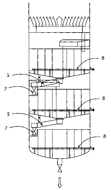
Figure 8 is showing a cross section of a side view of a tray column
according to another alternative embodiment of the invention.
SUBSTITUTE SHEET (RULE 26)

CA 02606416 2007-10-29
WO 2006/118518 7 PCT/SE2006/000503
Figure 9 is showing a cross section of a side view of a tray column
showing gas and vacuum ducts inside the column according
to one alternative embodiment.
Figure 10 is showing a cross section of a side view of a tray column
showing gas and vacuum ducts outside the column according
to another alternative embodiment.
Detailed description of the drawings
A spiral arrangement of baffles 1 is shown in Figure 1, forming a spiral
labyrinth of passages, in which the fluids flow from an inlet point 2 to an
exit point 3. In Figure 2, 3 and 4 are other arrangements of a spiral
labyrinth of passages disclosed. The fluids are directed through passages
to flow for as long time as possible before leaving the tray at exit point 3.
A duct 4 for sparging gas and vacuum are shown in the figures.
Depending on if the tray bottoms are turned upwards or downwards inlet
point 2 and exit point 3 may change place according to alternative
embodiments of the invention. In all Figures 1 to 4 a regulating valve is
mounted at or close to the exit point 3, the regulating valve is not shown
in the figures.
The fluids are leaving the trays at an exit point 3 in the tray and are
transferred to a collecting device 5 according to one alternative
embodiment. The collecting device is sloping sideways in the direction
towards the periphery of a tray below and over an inlet point not shown in
the figure. At the end point 6 of the collecting device is a regulating valve
7 mounted, which regulates the fluid flow in the passages of the tray
above. Sparging pipes 8 are mounted at the bottom of the tray.
Each tray is equipped with several sparging pipes 8 which can be seen in
Figure 6. Figure 6 shows also under lying collecting device 5 having
SUBSTITUTE SHEET (RULE 26)

CA 02606416 2007-10-29
WO 2006/118518 8 PCT/SE2006/000503
regulating valve 7. The bottoms of the plug flow trays in the tray column
can be horizontal, turned upwards or downwards. In figure 7 are the trays
both turned upwards and downwards according to one alternative
embodimen't. Tray 9 is turned downwards having an angle 0, which can
be less than 100. At the lowest point is an exit point 3 to which a
regulating valve 7 is mounted. The flow of fluids will be transferred from
the regulating valve mounted in the centre of tray to an inlet point 2 on
tray 10. Tray 10 is turned upwards. The flow of fluids will pass the
labyrinth of passages from the inlet point in the centre of the tray out to an
exit point 3 at the periphery. Mounted to exit point 3 is a regulating valve
7. Also Tray 10 is having an angle 0, which is less than 10 .
Figure 8 shows a tray column having only trays sloping downwards.
According to this alternative embodiment are the trays equipped with
collecting devices 5 and regulating valves 7, which are mounted at the
periphery of the column. Ducts 4 for vacuum, volatiles and sparging gas
according to one alternative embodiment are mounted inside the tray
column, which can be seen in Figure 9. Figure 10 is showing another
alternative embodiment wherein the ducts 4 are mounted outside the tray
column.
SUBSTITUTE SHEET (RULE 26)

Representative Drawing
A single figure which represents the drawing illustrating the invention.
Administrative Status

2024-08-01:As part of the Next Generation Patents (NGP) transition, the Canadian Patents Database (CPD) now contains a more detailed Event History, which replicates the Event Log of our new back-office solution.

Please note that "Inactive:" events refers to events no longer in use in our new back-office solution.

For a clearer understanding of the status of the application/patent presented on this page, the site Disclaimer , as well as the definitions for Patent , Event History , Maintenance Fee  and Payment History  should be consulted.

Event History

Description Date
Application Not Reinstated by Deadline 2014-02-17
Inactive: Dead - No reply to s.30(2) Rules requisition 2014-02-17
Deemed Abandoned - Failure to Respond to Maintenance Fee Notice 2013-04-26
Inactive: Abandoned - No reply to s.30(2) Rules requisition 2013-02-15
Inactive: S.30(2) Rules - Examiner requisition 2012-08-15
Letter Sent 2011-05-04
All Requirements for Examination Determined Compliant 2011-04-19
Request for Examination Requirements Determined Compliant 2011-04-19
Request for Examination Received 2011-04-19
Letter Sent 2008-06-09
Inactive: Single transfer 2008-04-01
Inactive: Correspondence - Formalities 2008-04-01
Inactive: Cover page published 2008-01-30
Inactive: Declaration of entitlement/transfer requested - Formalities 2008-01-29
Inactive: Notice - National entry - No RFE 2008-01-28
Inactive: First IPC assigned 2007-11-21
Application Received - PCT 2007-11-20
National Entry Requirements Determined Compliant 2007-10-29
Application Published (Open to Public Inspection) 2006-11-09

Abandonment History

Abandonment Date Reason Reinstatement Date
2013-04-26

Maintenance Fee

The last payment was received on 2012-04-13

Note : If the full payment has not been received on or before the date indicated, a further fee may be required which may be one of the following

  • the reinstatement fee;
  • the late payment fee; or
  • additional fee to reverse deemed expiry.

Patent fees are adjusted on the 1st of January every year. The amounts above are the current amounts if received by December 31 of the current year.
Please refer to the CIPO Patent Fees web page to see all current fee amounts.

Fee History

Fee Type Anniversary Year Due Date Paid Date
Basic national fee - standard 2007-10-29
Registration of a document 2008-04-01
MF (application, 2nd anniv.) - standard 02 2008-04-28 2008-04-18
MF (application, 3rd anniv.) - standard 03 2009-04-27 2009-03-20
MF (application, 4th anniv.) - standard 04 2010-04-26 2010-03-16
MF (application, 5th anniv.) - standard 05 2011-04-26 2011-03-16
Request for examination - standard 2011-04-19
MF (application, 6th anniv.) - standard 06 2012-04-26 2012-04-13
Owners on Record

Note: Records showing the ownership history in alphabetical order.

Current Owners on Record
ALFA LAVAL CORPORATE AB
Past Owners on Record
BJARNE GULLOV-RASMUSSEN
Past Owners that do not appear in the "Owners on Record" listing will appear in other documentation within the application.
Documents

To view selected files, please enter reCAPTCHA code :


To view images, click a link in the Document Description column. To download the documents, select one or more checkboxes in the first column and then click the "Download Selected in PDF format (Zip Archive)" or the "Download Selected as Single PDF" button.

List of published and non-published patent-specific documents on the CPD .

If you have any difficulty accessing content, you can call the Client Service Centre at 1-866-997-1936 or send them an e-mail at CIPO Client Service Centre.


Document
Description 
Date
(yyyy-mm-dd) 
Number of pages   Size of Image (KB) 
Description 2007-10-28 8 351
Representative drawing 2007-10-28 1 13
Drawings 2007-10-28 7 109
Claims 2007-10-28 4 165
Abstract 2007-10-28 2 66
Reminder of maintenance fee due 2008-01-27 1 113
Notice of National Entry 2008-01-27 1 195
Courtesy - Certificate of registration (related document(s)) 2008-06-08 1 104
Reminder - Request for Examination 2010-12-29 1 120
Acknowledgement of Request for Examination 2011-05-03 1 178
Courtesy - Abandonment Letter (R30(2)) 2013-04-14 1 165
Courtesy - Abandonment Letter (Maintenance Fee) 2013-06-20 1 173
PCT 2007-10-28 4 123
Correspondence 2008-01-27 1 24
Correspondence 2008-03-31 2 44