Language selection

Search

Patent 2607474 Summary

Third-party information liability

Some of the information on this Web page has been provided by external sources. The Government of Canada is not responsible for the accuracy, reliability or currency of the information supplied by external sources. Users wishing to rely upon this information should consult directly with the source of the information. Content provided by external sources is not subject to official languages, privacy and accessibility requirements.

Claims and Abstract availability

Any discrepancies in the text and image of the Claims and Abstract are due to differing posting times. Text of the Claims and Abstract are posted:

  • At the time the application is open to public inspection;
  • At the time of issue of the patent (grant).
(12) Patent: (11) CA 2607474
(54) English Title: ELECTROMECHANICAL LOCK DEVICE
(54) French Title: DISPOSITIF DE VERROUILLAGE ELECTROMECANIQUE
Status: Deemed Expired
Bibliographic Data
(51) International Patent Classification (IPC):
  • E05B 47/06 (2006.01)
(72) Inventors :
  • ANDERSSON, DANIEL (Sweden)
(73) Owners :
  • ASSA AB
(71) Applicants :
  • ASSA AB (Sweden)
(74) Agent: KIRBY EADES GALE BAKER
(74) Associate agent:
(45) Issued: 2014-09-09
(86) PCT Filing Date: 2006-04-27
(87) Open to Public Inspection: 2006-11-09
Examination requested: 2011-03-31
Availability of licence: N/A
Dedicated to the Public: N/A
(25) Language of filing: English

Patent Cooperation Treaty (PCT): Yes
(86) PCT Filing Number: PCT/SE2006/000506
(87) International Publication Number: SE2006000506
(85) National Entry: 2007-10-29

(30) Application Priority Data:
Application No. Country/Territory Date
0500977-4 (Sweden) 2005-04-29

Abstracts

English Abstract


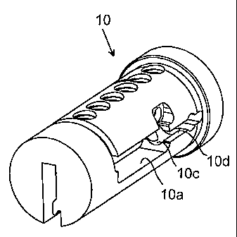
A lock device comprises a housing (2) which includes an opening (4) and a core
(10) which is rotatably mounted in the opening (4) about a longitudinal axis
of the core and which includes a key way (12) for reception of a key. A
latching element (20) co-acts between the housing (2) and the core (10). An
electronically controllable actuator (30) is mounted in the core (10) and
which is movable by means of a motor (40) between an opening-registering
position in which movement of the latching element (20) to the release
position is permitted, and a latching position in which movement of the
latching element (20) to the release position is blocked. The motor (40) is
provided in a recess (10a) in the barrel surface (10b) of the core at a
distance from the end surfaces of the core. Because the recess turns into a
bore (10c) having a cross-section that essentially correspond to the cross-
section of the actuator and which extends parallel to the longitudinal axis of
the core and in which the actuator (30) is provided; and that the latching
element (20) is provided in a slit (10d) provided between the bore and the
barrel surface of the core, the advantage is achieved that forces on the
latching element are taken up by the core itself, which improves the security.
The provision of the recess at a distance from the end surfaces of the core
gives at the same time a flexible solution as regards assembly. A method of
assembling the lock device is also described.


French Abstract

La présente invention concerne un dispositif de verrouillage comprenant un logement (2) qui inclut une ouverture (4) et un noyau (20) qui est monté de manière à pouvoir tourner dans l~ouverture (4) autour d~un axe longitudinal du noyau et qui inclut une fente de clé (12) pour la réception de la clé. Un élément de verrouillage (20) agit conjointement entre le logement 2) et le noyau (10). Un actionneur à commande électronique (30) est monté dans le noyau (10) et peut être déplacé au moyen d~un moteur (40) entre une position d~ouverture-coïncidence dans laquelle le déplacement de l~élément de verrouillage (20) en position de libération est permise et une position de verrouillage dans laquelle le déplacement de l~élément de verrouillage (20) en position de libération est bloquée. Le moteur (40) est disposé dans un évidement (10a) de la surface du canon (10b) du noyau à distance des surfaces d~extrémité du noyau. Le fait que l~évidement tourne dans un alésage (10c) présentant une coupe transversale correspondant essentiellement à la coupe transversale de l~actionneur et s~étendant parallèlement à l~axe longitudinal du noyau et dans lequel l~actionneur (30) est disposé et que l~élément de verrouillage (20) est disposé dans une fente (10d) située entre l~alésage et la surface de canon du noyau présente l~avantage que les forces exercées sur l~élément de verrouillage sont transférées vers le noyau lui-même, ce qui accroît la sécurité. La disposition de l~évidement à distance des surfaces d~extrémité du noyau constitue en même temps une solution souple en ce qui concerne le montage. Un procédé de montage du dispositif de verrouillage est également décrit.

Claims

Note: Claims are shown in the official language in which they were submitted.


7
CLAIMS
1. A lock device comprising:
a housing which includes an opening;
a core which is rotatably mounted in the opening about a longitudinal axis of
the
core and which includes a key way for reception of a key;
a latching element which co-acts between the housing and the core and which is
movable between a release position in which the core is rotatable relative to
the housing,
and a latching position in which rotation of the core relative to the housing
is blocked;
an electronically controllable actuator which is mounted in the core and which
is
movable by means of a motor between an opening-registering position in which
movement
of the latching element to the release position is permitted, and a latching
position in which
movement of the latching element to said release position is blocked;
wherein the motor is provided in a recess in a barrel surface of the core at a
distance from the end surfaces of the core;
a bore having a cross-section that essentially correspond to the cross-section
of the
actuator is arranged as a longitudinal extension of the recess, which bore
extends parallel
to the longitudinal axis of the core and in which the actuator is provided;
and
wherein the latching element is provided in a slit provided between the bore
and the
barrel surface of the core, wherein the recess opens at one radial side of the
barrel surface
of the core and the slit opens the bore at the one radial side of the barrel
surface such that a
mouth of the recess and the slit are arranged axially aligned in the barrel
surface.
2. The lock device according to claim 1, wherein the slit exhibits a width
essentially
corresponding to the width of the latching element.
3. The lock device accordingly to claim 2, wherein the latching element is
a side bar.
4. The lock device according to claim 1, wherein the latching element is a
side bar.

8
5. A method of assembling a lock device comprising a housing which includes
an
opening; a core which is rotatably mounted in the opening about a longitudinal
axis of the
core and which includes a key way for reception of a key; a latching element
which co-acts
between the housing and the core and which is movable between a release
position in
which the core is rotatable relative to the housing, and a latching position
in which rotation
of the core relative to the housing is blocked; and an electronically
controllable actuator
which is mounted in the core and which is movable by means of a motor between
an
opening-registering position in which movement of the latching element to the
release
position is permitted, and a latching position in which movement of the
latching element to
said release position is blocked; said method comprising the following steps:
providing a
recess in a barrel surface of the core; providing a bore as a longitudinal
extension of the
recess; providing a slit between the bore and the barrel surface of the core;
providing the
motor in the recess and the actuator in the bore; providing the latching
element in the slit;
and providing the core in the opening, wherein the recess opens at one radial
side of the
barrel surface of the core and the slit opens the bore at the one radial side
of the barrel
surface such that a mouth of the recess and the slit are arranged axially
aligned in the barrel
surface.
6. The method according to claim 5, wherein the bore is provided by means
of a ball
mill.
7. The method according to claim 6, wherein the slit exhibits a width
essentially
corresponding to the width of the latching element.
8. The method according to claim 6, wherein the latching element is a side
bar.
9. The method according to claim 5, wherein the slit exhibits a width
essentially
corresponding to the width of the latching element.

9
10. The method according to claim 9, wherein the latching element is a side
bar.
11. The method according to claim 5, wherein the latching element is a side
bar.

Description

Note: Descriptions are shown in the official language in which they were submitted.


CA 02607474 2007-10-29
1
WO 2006/118521
PCT/SE2006/000506
ELECTROMECHANICAL LOCK DEVICE
Field of invention
The present invention relates generally to an electromechanical lock device
and then
particularly to a lock device in which an electrically or electromechanically
operated latch
mechanism is provided in a recess in the barrel surface of a lock core.
Background of the invention
Electromechanical lock devices that include an electrically co-acting or
controlled latching
mechanism for manoeuvring a lock cylinder are known to the art. For example,
US patent
specification 5,839,307, the Swedish patent SE 9904771-4, and the European
patent
publication EP 1 134 335 A2 describe such lock devices. It is there described
how an actuator
is rotated by means of an electric motor. The actuator in turn permits or
prevents the
movement of a side bar.
In order to achieve greater flexibility it is preferred that the latching
mechanism is entirely
included in the cylinder core. In this way you can use the same lock cylinder
housing as in all-
mechanical lock devices. However, the problem is that the space in the
cylinder core is limited
and that the assembly of the latching mechanism can be difficult to realize in
a simple way.
A known way to assemble a latching mechanism entirely provided in the core is
to drill a hole
in the inner end surface of the core, which extends in the longitudinal
direction of the core.
The drawback with this solution is that such a hole in the end surface limits
the placement of
other parts in the lock device, such as the coupling of a follower to the
core.
It is also known to provide the latching mechanism in a recess in the barrel
surface of the core,
see for example the above mentioned European patent publication EP 1 134 335
A2. A
drawback associated with this solution is that a cover must be provided, which
keeps the
actuator and the side bar in place. This leads to a weakening of the latching
mechanism since
the cover can yield when the core is subjected to large turning forces.

CA 02607474 2012-12-20
2
Summary of the present invention
An object of the present invention is to provide a lock device of the above
kind in which the
electrically controlled latch mechanism exhibits more security than in prior
art devices and
which also is easier to assemble.
The invention is based on the insight that a bore can be provided by means of
a cutter or mill,
which bore extends parallel to the longitudinal direction of the core and in
which the actuator
is provided. This, in combination with the fact that the latching element is
provided in a slit
provided between the bore and the barrel surface of the core, solves the above
mentioned
problem in prior art.
One advantage afforded by the inventive lock device is that forces on the side
bar are taken up
by the core itself, which improves the security. The recess provided at a
distance from the end
surfaces of the core also gives a flexible solution as regards assembly.
Brief description of the drawings
The invention will now be described by way of example and with reference to
the
accompanying drawings, in which
FIG. 1 is a perspective view of a lock device according to the present
invention;
FIGS. 2a and 2b illustrate in detail a latch mechanism that comprises a side
bar, an actuator, a
motor, a pivotal pin, and a damping spring included in a lock device according
to the present
invention;
FIGS. 3a-c illustrate perspective views of a core comprised in a lock device
according to the
invention;
FIG. 4 illustrates a cross-section of the core in FIGS. 3a-c taken in level
with the actuator of
the latching mechanism;

CA 02607474 2007-10-29
3
WO 2006/118521
PCT/SE2006/000506
FIG. 5 illustrates a side view of the latching mechanism in an alternative
embodiment of the
invention;
FIGS. 6a-c illustrate top views of the latching mechanism shown in FIG. 5.
Detailed description of the invention
There follows a detailed description of preferred embodiments of the
invention.
FIG. 1 is an exploded view of a cylinder core, generally referenced 10, in a
lock device
constructed in accordance with the invention. The core 10 is structured for
placement in a
circular-cylindrical opening 4 in a typical cylinder housing 2 and the core
will therefore have
an outer surface which corresponds essentially to the housing opening. The
core includes a
key way 12 which is configured to receive a key (not shown) in a typical
fashion. The core 10
includes a plurality of pin tumbler openings 14 which receive tumbler pins
(not shown) in a
typical fashion. The manner in which an appropriately profiled key contacts
the tumbler pins
and places them on a parting line so that the core 10 can be rotated relative
to the housing is
known in the art and will not therefore will be described here in more detail.
The function or modus operandi of the tumbler pins is ignored throughout the
entire
description, and it is assumed and an appropriately profiled key has been
inserted in the lock.
When it is said, for instance, that the core is blocked or latched it is meant
that the core is
blocked by the electrically controlled latch mechanism described below.
FIG. 1 also illustrates a side bar 20 which is spring biased radially outwards
by a spring 22
acting on the side bar. The function of the side bar is described in detail
in, for instance,
Swedish patent application 79067022-4, which is included by reference in the
instant
application.
The core also includes a generally cylindrical actuator 30 which can be
rotated by means of a
motor 40. The motor is connected to an electronic module 48 by means of two
conductors
42a, 42b. These conductors extend in a groove in the barrel surface of the
core. In addition to
including a custom-made micro-regulating unit with an associated memory for
storing and
executing software together with drive circuits for driving the motor 40 etc,
the electronic

CA 02607474 2007-10-29
4
WO 2006/118521
PCT/SE2006/000506
*module also includes a key contact 44 in the form of an electrically
conductive metal strip
=
which is intended to make mechanical contact with a key inserted in the key
channel 12. This
enables the key and the electronic module to exchange electrical energy and
data. Thus, a
battery powering the motor 40 and the electronic module 48 can be placed
either in the lock
device or in the key. A damping spring 46 is provided radially inwards of the
motor for
damping rotation of the motor 40.
Rotation of the actuator 30 can also be influenced by a pivotal pin 50 which
has a rotational
axle that extends generally at right angles to the rotational axis of the
actuator. The pivotal pin
is disposed in a channel (not shown) that extends up to the key way 12.
The side bar 20, the actuator 30 and the motor 40 with associated components,
such as the
damping spring 46, are disposed in a recess 10a in the barrel surface 10b of
the core and are
held in place by a cover 18. Correspondingly, the electronic module 48 is
disposed in a recess
in the barrel surface of the core opposite the recess 10a.
The latch mechanism is shown in more detail in FIGS. 2a and 2b, wherein the
motor 40 has
been omitted in FIG. 2b.
In FIGS. 3a-c there are shown different perspective views of the core 10,
which all show the
recess 10a. It is here evident that the recess 10a is provided at a distance
from the end surfaces
of the core. With the expression "at a distance" is also meant that you do not
drill though the
end surface in order to provide the recess, even though the provided opening
later is sealed.
The recess 10a later turns into an essentially circular bore 10c, which
extends parallel with the
longitudinal axis of the core and in which the actuator 30 is provided, see
FIG. 4. It is also
seen that the latching element in the form of the side bar 20 is provided in a
slit 10d provided
between the circular bore and the barrel surface of the core.
Because the lock device exhibits a circular bore, which extends parallel to
the longitudinal
axis of the core and in which the actuator is provided, good strength is
obtained. This also
applies to the placement of the side bar in a slit between the circular bore
and the barrel
surface of the core, which further enhances the security. The provision of the
recess at a
distance from the end surfaces of the core gives at the same time a flexible
solution as regards
assembly.

CA 02607474 2007-10-29
WO 2006/118521
PCT/SE2006/000506
The slit 10d has preferably a width which essentially corresponds to the width
of the side bar
20.
5 The described lock device is assembled in the following way. First the
recess 10a is provided
in the barrel surface of the core 10 by means of a cutter or mill. Thereafter,
starting from the
recess 10a, the circular bore 10c is provided by means of a ball mill. Then
the pivotal pin 50,
the springs 22, 46, and 52, the actuator 30 and the motor 40, the side bar 20
and finally the
cover 46 are assembled in the above mentioned order. The motor and the
actuator are placed
so that the actuator is placed in the circular bore 10c while the side bar is
placed in the slit
10d.
In an alternative embodiment illustrated in FIGS. 5 and 6a-c, the motor 40
with a rotating
shaft has been replaced by a linearly operating motor or solenoid 140. This is
connected to an
actuator 130 which is movable in a longitudinal direction. A hole 130a is
provided in the
actuator 130, which hole is arranged to receive a pin 120a on a side bar 120.
In the position
illustrated in FIG. 6a the side bar can thus be moved towards the actuator
since its pin is in
registry with the hole 130a.
A damping spring 146 corresponding to the above described spring 46 abuts the
shaft
interconnecting the motor and the actuator.
A pivotal pin 150 corresponding to the pin of the first embodiment is provided
for mechanical
movement of the actuator during removal of the key from the lock device. It is
thus provided
with a pin 150a or other means making it possible to be influenced by means of
a key inserted
into the lock device. It is also spring biased by means of a spring (not
shown). During turning
of the pivotal pin, see FIG. 6b, a surface thereof presses against the end
surface of the
actuator, wherein the actuator is given a linear movement in the direction of
the motor, see
FIG. 6c. The hole 130a is thereby moved out of registry with the pin 120a of
the side bar 120
and the side bar is thereby prevented from being moved inwardly towards the
actuator. The
actuator 130 is thereby given the same function as the rotating actuator 30 in
the first
embodiment. Although the actuator in this second embodiment is not rotating
this latching
mechanism can be assembled in a way corresponding to the way the latching
mechanism of
FIGS. 2a and 2b is assembled, i.e., the recess 10a and the circular bore 10c
are replaced by

CA 02607474 2012-12-20
6
spaces corresponding to the shape of the parts of the latching mechanism shown
in FIGS. 5
and 6a-c.
A lock device according to the present invention and a method of assembling
the same have
been described with reference to preferred embodiments thereof.
Although a combination of an electrically controlled latch mechanism and
conventional pin
tumblers has been illustrated it will be understood that the concept of the
invention can also be
applied to lock devices that lack other latching devices than the
electronically controlled latch
mechanism described above.
The latching element has been described in the form of a side bar 20. It will
be appreciated
that the actuator 30 can cooperate with other kinds of latching elements, such
as a latching pin
with a function corresponding to that of the described side bar.
The expression bore has been used throughout this description for the space in
which the
actuator is provided. It will be appreciated that this expression is to be
considered to cover
spaces for the actuator provided in different ways.

Representative Drawing
A single figure which represents the drawing illustrating the invention.
Administrative Status

2024-08-01:As part of the Next Generation Patents (NGP) transition, the Canadian Patents Database (CPD) now contains a more detailed Event History, which replicates the Event Log of our new back-office solution.

Please note that "Inactive:" events refers to events no longer in use in our new back-office solution.

For a clearer understanding of the status of the application/patent presented on this page, the site Disclaimer , as well as the definitions for Patent , Event History , Maintenance Fee  and Payment History  should be consulted.

Event History

Description Date
Letter Sent 2024-04-29
Letter Sent 2023-10-27
Letter Sent 2023-04-27
Inactive: COVID 19 - Deadline extended 2020-03-29
Common Representative Appointed 2019-10-30
Change of Address or Method of Correspondence Request Received 2018-01-09
Grant by Issuance 2014-09-09
Inactive: Cover page published 2014-09-08
Pre-grant 2014-06-27
Inactive: Final fee received 2014-06-27
Notice of Allowance is Issued 2014-05-15
Letter Sent 2014-05-15
Notice of Allowance is Issued 2014-05-15
Inactive: Approved for allowance (AFA) 2014-05-07
Inactive: Q2 passed 2014-05-07
Amendment Received - Voluntary Amendment 2014-01-15
Inactive: S.30(2) Rules - Examiner requisition 2013-07-16
Amendment Received - Voluntary Amendment 2012-12-20
Inactive: S.30(2) Rules - Examiner requisition 2012-06-22
Amendment Received - Voluntary Amendment 2011-11-02
Letter Sent 2011-04-13
All Requirements for Examination Determined Compliant 2011-03-31
Request for Examination Requirements Determined Compliant 2011-03-31
Request for Examination Received 2011-03-31
Inactive: Declaration of entitlement/transfer requested - Formalities 2008-01-29
Inactive: Cover page published 2008-01-25
Inactive: Notice - National entry - No RFE 2008-01-23
Inactive: Declaration of entitlement - Formalities 2008-01-15
Inactive: First IPC assigned 2007-11-27
Application Received - PCT 2007-11-26
National Entry Requirements Determined Compliant 2007-10-29
Application Published (Open to Public Inspection) 2006-11-09

Abandonment History

There is no abandonment history.

Maintenance Fee

The last payment was received on 2014-04-09

Note : If the full payment has not been received on or before the date indicated, a further fee may be required which may be one of the following

  • the reinstatement fee;
  • the late payment fee; or
  • additional fee to reverse deemed expiry.

Patent fees are adjusted on the 1st of January every year. The amounts above are the current amounts if received by December 31 of the current year.
Please refer to the CIPO Patent Fees web page to see all current fee amounts.

Owners on Record

Note: Records showing the ownership history in alphabetical order.

Current Owners on Record
ASSA AB
Past Owners on Record
DANIEL ANDERSSON
Past Owners that do not appear in the "Owners on Record" listing will appear in other documentation within the application.
Documents

To view selected files, please enter reCAPTCHA code :


To view images, click a link in the Document Description column. To download the documents, select one or more checkboxes in the first column and then click the "Download Selected in PDF format (Zip Archive)" or the "Download Selected as Single PDF" button.

List of published and non-published patent-specific documents on the CPD .

If you have any difficulty accessing content, you can call the Client Service Centre at 1-866-997-1936 or send them an e-mail at CIPO Client Service Centre.


Document
Description 
Date
(yyyy-mm-dd) 
Number of pages   Size of Image (KB) 
Abstract 2007-10-28 1 71
Description 2007-10-28 6 300
Claims 2007-10-28 2 84
Representative drawing 2007-10-28 1 5
Drawings 2007-10-28 3 65
Description 2012-12-19 6 285
Claims 2012-12-19 2 78
Claims 2014-01-14 3 94
Representative drawing 2014-08-13 1 9
Commissioner's Notice - Maintenance Fee for a Patent Not Paid 2024-06-09 1 533
Reminder of maintenance fee due 2008-01-22 1 113
Notice of National Entry 2008-01-22 1 195
Reminder - Request for Examination 2010-12-29 1 119
Acknowledgement of Request for Examination 2011-04-12 1 178
Commissioner's Notice - Application Found Allowable 2014-05-14 1 161
Commissioner's Notice - Maintenance Fee for a Patent Not Paid 2023-06-07 1 540
Courtesy - Patent Term Deemed Expired 2023-12-07 1 537
PCT 2007-10-28 3 102
Correspondence 2008-01-22 1 25
Correspondence 2008-01-14 2 52
Correspondence 2014-06-26 1 36