Language selection

Search

Patent 2607535 Summary

Third-party information liability

Some of the information on this Web page has been provided by external sources. The Government of Canada is not responsible for the accuracy, reliability or currency of the information supplied by external sources. Users wishing to rely upon this information should consult directly with the source of the information. Content provided by external sources is not subject to official languages, privacy and accessibility requirements.

Claims and Abstract availability

Any discrepancies in the text and image of the Claims and Abstract are due to differing posting times. Text of the Claims and Abstract are posted:

  • At the time the application is open to public inspection;
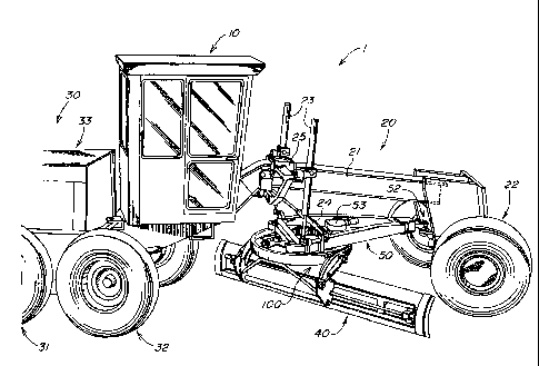
  • At the time of issue of the patent (grant).
(12) Patent: (11) CA 2607535
(54) English Title: FULL SUPPORT BEARING FOR GRADER CIRCLE
(54) French Title: PALIER A SUPPORT COMPLET POUR CERCLE DE NIVELEUSE
Status: Granted and Issued
Bibliographic Data
(51) International Patent Classification (IPC):
  • E02F 3/815 (2006.01)
  • E02F 3/80 (2006.01)
(72) Inventors :
  • STUBBEN, DAVID WILLIAM (United States of America)
(73) Owners :
  • DEERE & COMPANY
(71) Applicants :
  • DEERE & COMPANY (United States of America)
(74) Agent: BORDEN LADNER GERVAIS LLP
(74) Associate agent:
(45) Issued: 2014-12-23
(22) Filed Date: 2007-10-22
(41) Open to Public Inspection: 2008-04-30
Examination requested: 2012-10-19
Availability of licence: N/A
Dedicated to the Public: N/A
(25) Language of filing: English

Patent Cooperation Treaty (PCT): No

(30) Application Priority Data:
Application No. Country/Territory Date
11/590,391 (United States of America) 2006-10-31

Abstracts

English Abstract

A full support bearing for a grader circle including a first radial groove in a cylindrical portion of the circle includes a group of inserts forming a second support groove within the first radial groove. It also includes circle supports sized and shaped such that the gap between any two circle supports is small. The circle supports are arranged along a circumference of the circle and rigidly attached to a draw bar. The arrangement results in virtual 360 degree circle support, lower loads and smaller material deflections at all loaded areas, and significantly increased durability due to a resultant reduction in wear rates.


French Abstract

Un palier à support complet pour cercle de niveleuse, comprenant une première rainure radiale dans une portion cylindrique du cercle, est muni d'une série d'éléments qui forment une seconde rainure à l'intérieur de la première rainure radiale. L'invention comprend également des supports de cercle dont la forme et la taille permettent un petit écart entre deux supports de cercle. Les supports de cercle sont disposés le long de la circonférence du cercle et sont solidement fixés à la barre d'attelage, pour créer un support de cercle pratiquement sur toute sa circonférence, diminuer les efforts et restreindre les déflexions des matériaux dans toutes les zones soumises aux efforts, et augmenter de façon importante la durabilité en raison d'une réduction du taux d'usure.

Claims

Note: Claims are shown in the official language in which they were submitted.

Claims
1. A blade assembly for a motor grader comprising:
a draw bar assembly;
a blade;
a circle for mounting the blade, the circle having a circle gear portion and a
circle support portion, the circle support portion having an inner cylindrical
surface,
the inner cylindrical surface including a first support groove;
a plurality of inserts; and
a plurality of support shoes, each one of the plurality of support shoes
rigidly
mounted to the drawbar assembly, the each one of the plurality of support
shoes
having a free end, the each one of the plurality of inserts arranged in the
support
groove to expose an inner insert surface, the inner insert surface forming a
second
support groove, the free end being arranged to fit within the second support
groove,
the inserts arranged such that the sum of all gaps between the inserts is a
predetermined minimal value.
2. The blade assembly of claim 1, wherein the plurality of support shoes
comprises six support shoes.
3. The blade assembly of claim 1, wherein the predetermined minimal value
is
less than 25 mm.
4. The blade assembly of claim 1, wherein the predetermined minimal value
is
less than 10 mm.
5. The blade assembly of claim 1, wherein the each one of the plurality of
inserts
is formed from a plastic material.
6

6. The blade assembly of claim 1, wherein the support shoes support all
loads
experienced by the blade.
7. The blade assembly of claim 1, wherein at least one of the plurality of
support
shoes is reinforced to support greater loads experienced by the blade.
8. The blade assembly of claim 1, wherein the plurality of support shoes is
arranged such that a shoe gap between any two free ends is less than the
predetermined minimal value.
7

Description

Note: Descriptions are shown in the official language in which they were submitted.


CA 02607535 2014-02-13
FULL SUPPORT BEARING FOR GRADER CIRCLE
Field of the Invention
[0001] The invention relates to a mechanism and method for increasing the
durability of a structural support for a circle of a motor grader. More
particularly, the
invention relates to a structural support system for reducing the wear on
structural
supports relative to the circle of a motor grader.
Background of the Invention
[0002] Motor graders include, inter alia, a longitudinal mainframe having at a
forward end, a wheel support and, at a rear end, an operator's cab; and a rear
frame
of for the motor and power train located behind the cab. The motor grader
blade is
suspended from the mainframe by means of a draw bar and a circle. The circle
is
mounted on the rear portion of the draw bar and must, typically, be controlled
with a
high degree of precision.
[0003] The blade of the motor grader must, typically, be controlled with a
high
degree of precision as it often serves as a finishing instrument. The surfaces
on
which the circle rotates are, due to their locations and structures, generally
subject to
somewhat high rates of wear. Thus, conventional motor graders typically
require
frequent adjustment to satisfactorily perform their accurate finish operations
as
excessive wear results in imprecision with respect to blade control.
Summary of the Invention
[0004] As stated above, conventional motor graders typically require frequent
adjustment to satisfactorily perform their finish operations to the degree of
accuracy
usually required. This is at least partially due to rapid wear on circle wear
inserts.
Typically, there are 12 wear inserts, as well as six circle supports, at six
specific and
1

CA 02607535 2014-02-13
discreet support locations around the circle. Such is typical of all
manufactures.
Additionally, the locations of the wear inserts and circle supports allow
significant
material deflections under load. These deflections result in increased normal
loads at
the end of at least two and circle supports. Elevated normal loads cause
increased
friction and reduced circle efficiency and torque.
[0005] The invention provides positions, sizes and shapes of circle wear
inserts and
circle supports to support the circle at virtually every point around its 360-
degree
perimeter. Thus, the circle is virtually completely supported in both
horizontal and
vertical directions.
[0006] Due to the very large wear area provided by the invention, normal loads
are
reduced and wear life is increased to allow a significantly longer time of
blade use
without adjustment. Further, the efficiency of the circle is increased as the
normal
loads and material deflections are greatly reduced.
Brief Description of the Drawings
[0007] The invention will be described in detail, with references to the
following
figures, wherein:
[0008] Fig. 1 is a view of the work vehicle in which the invention may be
used;
Fig. 2 is a bottom view of the draft frame and circle assembly of Fig. 2
illustrating an exemplary embodiment of the circle supports of the invention
in one
state;
Fig. 3 is a bottom view of the draft frame in an alternate state;
Fig. 4 is a section view of the assembly of Fig. 2 illustrating an exemplary
embodiment of an unreinforced circle support as well as a second support
groove of
the invention;
2

CA 02607535 2014-02-13
Fig. 5 is a section view of the assembly of Fig. 2 illustrating an exemplary
embodiment of the reinforced circle support and the second support groove of
the
invention;
Fig. 6 is an exploded a view illustrating a reinforced circle support;
Fig. 7 illustrates a prior art circle support; and
Fig. 8 illustrates a cross section of the prior art circle support of Fig. 7.
Description of the Preferred Embodiment
[0009] Figure 1 as an illustration of a motor grader 1 in which the invention
may be
used. As illustrated in Fig. 1, the motor grader 1 includes a cab 10, a front
portion 20
and a rear portion 30. The front portion 20 includes: a longitudinal mainframe
21; a
front wheel assembly 22; a circle group 100; a blade assembly 40: joint lift
cylinders
23; a draw bar 50; and a maneuvering cylinder 24. The rear portion 30
includes: a
rear frame 33; four wheels 31, 32; a propulsion system (not shown); and a
hydraulic
system (not shown).
[0010] The hydraulic cylinders 23 and a maneuvering cylinder 24 are pivotally
attached to longitudinal mainframe 21 via bracket 25. The draw bar 50 is
pivotally
attached to a front end of the front portion 20 via socket 52 and suspended
from a
rear portion of the mainframe 21 via pivotal attachments to the hydraulic lift
cylinders
23 and the maneuvering cylinder 24.
[0011] As illustrated in Fig. 2 the circle group 100 includes: a circle 101;
support
shoes 110, 120; and plastic inserts 130. The circle 101 includes a ring gear
portion
102 and a cylindrical support portion 103. The cylindrical support portion 103
includes a radial support groove 104 in which a plurality of plastic inserts
130 form a
second radial support groove 131. In this particular exemplary embodiment of
the
invention, the draw bar 50 includes at least six internally threaded spacer
blocks 51
welded equidistant along a circumference of the circle attachment area 50' of
the
draw bar 50. Each of the support shoes 110,120 is attached to the circle
attachment
3

CA 02607535 2014-02-13
area 50' of the drawbar 50 via screws 113 for support shoes 110, screws 114
for
reinforced support shoes 120 and one of the threaded spacer blocks 51 as
illustrated
in Figure 2. A free end 110a, 120a of each of the support shoes 110, 120 rests
in the
second radial support groove 131. Thus, the circle 101 is supported via the
second
radial support groove 131 and the free ends 110a, 120a of the support shoes
110,
120. A power device 53 moves the circle 101 in a circular direction when
actuated.
[0012] In practice, the plastic inserts 130 are arranged such that a minimal
gap G,
as illustrated in Figure 2, exists between them. If, as illustrated in Figure
3, the total
gap TG with the inserts pushed one-way is more than 25 mm, a segment from
another new insert 130 is placed in the radial support groove 104 to bring the
total
gap TG to within about 1 mm to 10 mm. As illustrated in Figures 4, 5 and 6,
the free
end 110a, 120a of each of the support shoes 110, 120 is dimensioned to
complement the second radial support groove 131 and to slide within it.
Further, the
free ends 110a, 120a of the support shoes 110, 120 are dimensioned and
arranged
such that the largest gap between any two free ends 110a, 120a is less than 25
mm
preventing any segment from a new insert 130 from leaving the second radial
support
groove 131. Thus, the plastic inserts 130 and the support shoes 110, 120 form
a
virtual 360-degree bearing on which the circle 110 rotates. With such an
arrangement, the circle 101 has support at virtually every point along a 360-
degree
circumference. Thus, in comparison to the prior art, wear of the 360 degree
bearing
is significantly reduced as the load and geometric distortion, i.e., material
deflection,
at any particular point of support is significantly reduced.
[0013] Figures 7 and 8 illustrate the differences between prior art support
shoes 60
and the support shoes 110 of the invention as illustrated in Figure 2. As
illustrated,
the major differences between prior art support shoes 70 and support shoes 110
of
the invention is the circle contact area afforded by the contrasting free end
widths.
As illustrated in Figures 7 and 8 to prior art inserts 71, 72 are affixed to
the free end
of each of the prior art support shoes 70; no other inserts are evidenced in
the prior
art. Further, Fig. 7 shows that the contact area between the support shoes 70
and
4

CA 02607535 2014-02-13
the circle 60 is relatively small. Small contact areas in this environment
result in
material distortions or deflections in the areas of contact, excessive wear
and lower
operating efficiency. Excessive wear resultant frequent adjustments and higher
maintenance costs. This is to be contrasted with the advantages of the 360-
degree
contact afforded by the invention as well as the consequent improvements with
respect to material deflections, wear and operating efficiency.
[0014] Having described the illustrated embodiment, it will become apparent
that
various modifications can be made without departing from the scope of the
invention
as defined in the accompanying claims.

Representative Drawing
A single figure which represents the drawing illustrating the invention.
Administrative Status

2024-08-01:As part of the Next Generation Patents (NGP) transition, the Canadian Patents Database (CPD) now contains a more detailed Event History, which replicates the Event Log of our new back-office solution.

Please note that "Inactive:" events refers to events no longer in use in our new back-office solution.

For a clearer understanding of the status of the application/patent presented on this page, the site Disclaimer , as well as the definitions for Patent , Event History , Maintenance Fee  and Payment History  should be consulted.

Event History

Description Date
Maintenance Fee Payment Determined Compliant 2024-10-18
Maintenance Request Received 2024-10-18
Common Representative Appointed 2019-10-30
Grant by Issuance 2014-12-23
Inactive: Cover page published 2014-12-22
Pre-grant 2014-10-10
Inactive: Final fee received 2014-10-10
Letter Sent 2014-04-17
Notice of Allowance is Issued 2014-04-17
Inactive: Q2 passed 2014-04-04
Inactive: Approved for allowance (AFA) 2014-04-04
Amendment Received - Voluntary Amendment 2014-02-13
Inactive: S.30(2) Rules - Examiner requisition 2013-12-16
Inactive: Report - No QC 2013-11-28
Letter Sent 2012-11-05
Request for Examination Received 2012-10-19
Request for Examination Requirements Determined Compliant 2012-10-19
All Requirements for Examination Determined Compliant 2012-10-19
Application Published (Open to Public Inspection) 2008-04-30
Inactive: Cover page published 2008-04-29
Inactive: IPC assigned 2008-01-30
Inactive: First IPC assigned 2008-01-30
Inactive: IPC assigned 2008-01-30
Inactive: Filing certificate - No RFE (English) 2007-12-06
Filing Requirements Determined Compliant 2007-12-06
Application Received - Regular National 2007-11-26

Abandonment History

There is no abandonment history.

Maintenance Fee

The last payment was received on 2014-10-02

Note : If the full payment has not been received on or before the date indicated, a further fee may be required which may be one of the following

  • the reinstatement fee;
  • the late payment fee; or
  • additional fee to reverse deemed expiry.

Please refer to the CIPO Patent Fees web page to see all current fee amounts.

Owners on Record

Note: Records showing the ownership history in alphabetical order.

Current Owners on Record
DEERE & COMPANY
Past Owners on Record
DAVID WILLIAM STUBBEN
Past Owners that do not appear in the "Owners on Record" listing will appear in other documentation within the application.
Documents

To view selected files, please enter reCAPTCHA code :


To view images, click a link in the Document Description column. To download the documents, select one or more checkboxes in the first column and then click the "Download Selected in PDF format (Zip Archive)" or the "Download Selected as Single PDF" button.

List of published and non-published patent-specific documents on the CPD .

If you have any difficulty accessing content, you can call the Client Service Centre at 1-866-997-1936 or send them an e-mail at CIPO Client Service Centre.


Document
Description 
Date
(yyyy-mm-dd) 
Number of pages   Size of Image (KB) 
Description 2014-02-13 5 194
Claims 2014-02-13 2 42
Drawings 2014-02-13 6 221
Description 2007-10-22 5 196
Abstract 2007-10-22 1 16
Drawings 2007-10-22 6 232
Claims 2007-10-22 2 43
Representative drawing 2008-04-14 1 31
Cover Page 2008-04-22 2 64
Representative drawing 2014-12-01 1 32
Cover Page 2014-12-01 1 60
Confirmation of electronic submission 2024-10-18 3 78
Filing Certificate (English) 2007-12-06 1 159
Reminder of maintenance fee due 2009-06-23 1 110
Reminder - Request for Examination 2012-06-26 1 116
Acknowledgement of Request for Examination 2012-11-05 1 175
Commissioner's Notice - Application Found Allowable 2014-04-17 1 161
Correspondence 2014-10-10 1 30