Note: Descriptions are shown in the official language in which they were submitted.
CA 02607712 2007-10-26
-1-
October 17, 2007
Drossbach GmbH & Co. KG D108926US Al/blo
Device for the application of plastic to a workpiece
The invention concerns a device for the application of plastic to a
workpiece. Additionally, the invention concerns a method of production
for a plastic corrugated pipe by means of the invented device as well as the
plastic pipe produced by this method.
EP 1 243 400 B 1 describes a device for the production of corrugated pipes
which will allow the production of an indefinite amount of plastic pipes
with corrugated surfaces by means of an extruder device and a subsequent
molding section. Such corrugated surfaces provide the highest pipe ring
stiffness for the least amount of material. It may be desirable to cover
these or similar pipes with an additional outer coating of plastic by
request.
It is the invention's task to provide a device for the application of plastic
to
workpieces which makes smooth application in the circumferential
direction possible for large workpieces.
This task is achieved by the invented device with the features in Claim 1.
An especially smooth application of plastic in the circumferential direction
of the workpiece is made possible by a distribution area with a ring-shaped
gate.
CA 02607712 2007-10-26
-2-
In the preferred version, the supply region contains a first, tubular supply
line which branches into a number of secondary supply lines. In this way,
the supply region already achieves the first allocation of the plastic into at
least two supply lines, which is ultimately to be applied as homogeneously
as possible over the surface. It is preferred that at least one of the
secondary supply lines branch into a number of tertiary supply lines, so
that at least three and preferably four separate, evenly applied supply lines
are present over the surface. The lines of the respective branching planes
can then fall off to their widths according to the distribution of the plastic
current.
Also beneficially, the supply region contains a number of distribution
channels extending outwards from it in the circumferential direction of the
circular opening. Thereby, the distribution channels are advantageously
branched into at least one distribution plane. In this way, an additionally
branching pre-allocation over the surface of the workpiece is already made
possible in the area of the plastic supply.
In the interests of achieving simple and effective production with easy
maintenance access, the distribution plane contains a number of plate
elements, where the distribution channels are molded to the plate elements.
Practically, the plate elements are arranged on top of one another in the
axial direction, so that the channels can be developed as grooves or bores
in the circumferential direction.
In order to guarantee sufficient pre-allocation of the plastic in the supply
region, particularly for workpieces with large diameters, the plastic flows
in a preferred embodiment from the supply region to the distribution
region over at least 16, particularly at least 32 canals distributed in the
CA 02607712 2007-10-26
-3-
circumferential direction of the opening. In a generally advantageous
manner, the number of input points corresponds to a potency of 2.
In the preferred embodiment of the invention, the distribution area has a
ring-shaped cavity, where the plastic flows into the cavity through a
number of feed canals distributed in the circumferential direction and
escapes from the cavity through an annular gap. The circular cavity brings
about a homogenization of the plastic flow, so that the annular gap
receives an even flow from the typically highly viscous material. In an
advantageous embodiment, the cavity has a decreasing width in the radial
direction from the outside inwards. In this way, the passage width for the
plastic flow decreases in the direction of the flow, which leads to the
desired backlog. Particularly importantly, the cross-section takes the form
of a triangle shrinking in the radial direction. The plastic has a main
direction of flow in the distribution area cavity which runs radially from
the outside inwards; a flow in the circumferential direction can be
superimposed over this main direction of flow. It has been shown that this
configuration allows good homogenization of the plastic to be achieved
with a relatively small space available for the distribution area, especially
for workpieces with large diameters. In addition, this solution is simple to
produce and mechanically stable even at high pressure.
In an advantageous embodiment, the cavity has a wall with a number of
spiral grooves. The plastic mass is admitted into these grooves with a flow
in the circumferential direction, where manipulation of the individual flow
sections takes place following the construction of the grooves in order to
assure good homogenization of the plastic. For this purpose, the wall
preferably makes an angle with the radial plane, perpendicular to
CA 02607712 2007-10-26
-4-
the axial direction, which is less than about 45 , particularly less than 30 ,
particularly between about 18 and 25 .
A simple possibility for fine-tuning of the plastic flow in the distribution
area is offered when at least some, particularly several of the feed canals
have a throttle element for adjusting the width of the canals. In a simple
construction, each throttle element can have an adjusting screw protruding
into the canal. The throttle elements are advantageously distributed
throughout the device and adjustable from the outside so that, in particular,
adjustments of the throttle elements can be made while the device is in
use. In this way, changes due to temperature or fouling in the areas where
the plastic is flowing can be reacted to during production.
In a simply-constructed realization, the distribution area includes a ring-
shaped distribution disk, where a wall of the cavity is molded to the
distribution disk on the axial front side. The feed canals to the cavity are
then developed as appropriately distributed axial bores throughout the
distribution disk. If the feed canals are furnished with throttle elements,
they can functionally constitute radial thread canals, through each of
which an adjustment screw opens into the feed canals.
In an advantageous embodiment of the invention, the nozzle area has a
rotationally symmetric annular gap in the axial direction, so that the plastic
flows from the distribution area through the annular gap to the outlet slot.
The annular gap does not have a web over its run, so that the
homogenization of the plastic flow in the circumferential direction is not
influenced.
CA 02607712 2007-10-26
-5-
In the preferred embodiment, the annular gap has at least a first and a
second section, where the first section runs axially and the second at an
angle to the axial direction. By dividing the annular gap into different
sections, an additional optimization of the plastic flow, particularly
regarding changes in pressure and flow velocity, can be achieved. It is
particularly preferred that at least one of the two sections have a
decreasing width throughout its run, so that a targeted accumulation of the
plastic occurs.
In a particularly optimal embodiment, the first section of the annular gap
comes first in the direction of flow and opens to the distribution area and
the second section follows the first section, where the second section has
conical walls with different cone angles.
In a more complete implementation, the annular gap also has a barrier ring
area, where a local decrease in width of the annular gap is accomplished
through the barrier ring area. In this way, a targeted accumulation of
plastic can be achieved at an appropriate distance from the outlet. The
width decrease can, for example, be formed by an axially cylindrical
opening of particularly small passage width or as a ring-shape projection
which protrudes locally into the opening in order to decrease the width.
In a preferred implementation, the outlet opening is designed as the last
section of the annular gap, where the outlet has a conical wall angled
radially inwards in the direction of flow of the plastic. In an advantageous
embodiment, the outlet opening has two conical walls with different cone
angles, where the width of the outlet decreases in the direction of flow of
the plastic. In this simple way, a particularly even and fluctuation-free
mass flow of the exiting plastic is ensured.
CA 02607712 2007-10-26
-6-
In order to make adjustments possible and in the general interest of simple
production, the outlet opening is placed between the first ring element and
the second ring element in the nozzle area. It is particularly preferred that
the outlet be modifiable through mobility of at least one of the ring
elements.
In an advantageous implementation, the mobility is effected through an
elastic deformation of the ring elements by means of radial prestressing
tendons. In a simply-constructed realization, the tendons consist of a
number of clamping bolts distributed radially throughout the ring element,
where the clamping bolts are adjustable when the device is in use.
Through the thus ensured possibility of the radial deformation of at least
one of the ring elements, the homogenization of the material flow can be
optimized in the circumferential direction, where changes during
operation, for example in pressure distribution or mechanical deformation
due to pressure and temperature, can be caught.
Alternatively or complementarily, it is intended for the first ring element
and the second element to the adjustable relative to one another in the
axial direction. In this way, this size of the outlet opening is modifiable
over the entire device. In a simple implementation, changeable spacing
means are placed with one of the ring elements to adjust the distance
between it and the second ring element.
Alternatively or complementarily to the changeable spacing means, the
first ring element can be adjusted to at least one thread relative to the
second ring element. In this way, a simple and continuous adjustment is
CA 02607712 2007-10-26
-7-
made possible which, according to design, can also be carried out while
the device is in use.
In a particularly preferred implementation, a second thread is included,
where the first and second thread have a different pitch. In this way, a
differential thread is made possible, where a differential thread can
generally make fine adjustments in distance possible. In a simply-
constructed realization, a threaded ring that can be rotated for axial
adjustment works together with the two threads. The first ring element and
the second element are then axially conducted to one another by an axial
guide element. In this way, a particularly precise compulsory guide is
made possible, which limits the mobility exactly to the axial direction. The
axial guide element can consist simply of guided pins or other structures
that are free of float conducted into bore holes.
It is generally preferable for the device to have a means of heating to heat
the surface of the workpiece. In this manner, the surface of the workpiece
can be heated to a specific temperature before the application of the
plastic. This makes it possible to melt the surface, especially of
workpieces made from thermoplastic materials, so that the plastic can
form a good adhesive, molecular binding with the surface. Appropriate
means of heating include electrical resistance heating, especially ceramic
heating, or radiant heating systems with light, lasers, infrared radiation,
microwaves, or similar means. Hot air heating or other suitable heating
systems are also possible.
In a preferred implementation, the device has at least one elastic stripper
slidably leaning against the workpiece. The workpiece can be guided by
such strippers. In particular, a rough airtight seal can be achieved, creating
CA 02607712 2007-10-26
-8-
a closed and pressurized cavity between workpiece, plastic flow, and
device. In this way, it becomes possible to mold the soft plastic hose in the
course of the task. This is particularly important when cavities and furrows
are trapped in the workpiece by the applied plastic, as the gas pressure in
these cavities can be adjusted in this way.
In a particularly preferred implementation, the workpiece is a corrugated
pipe, where the applied plastic forms a fairly even exterior wall of the
corrugated pipe. The corrugated pipe preferably has a smooth interior wall.
Such corrugated pipes with smooth interior walls are well-known and have
many uses, for example as canalization pipes, and are in growing demand.
Until now, the application of an additional smooth layer from the outside
has been problematic, especially in the case of pipes with large diameters.
The plastic preferably consists of a polyolefin or another plastic with good
stability when heated.
In a preferred implementation, the workpiece is a pipe with an outer
diameter of at least 700 mm. It is particularly preferred that the outer
diameter of the pipe add up to over 1200 mm, especially around 1800 mm.
It has been shown that a device of the invented construction is particularly
suited for the application of a layer of plastic to very large pipes, where
the
applied layer is very homogenous, especially in the circumferential
direction.
In a more preferred implementation of the invention, distribution area is
intended to have a ring-shaped cavity, where the plastic flows into the
cavity through a number of feed canals distributed in the circumferential
CA 02607712 2007-10-26
-9-
direction and exits the cavity through a surrounding annular gap. In this
way, the cavity preferably has an inner side wall shaped to an inner
distribution part and, across from this, an outer side wall shaped to an
outer distribution part, where each of the side walls generally has the form
of a conic section. Due to the conic section form of the two walls, the
cavity is overall angled with respect to the axial direction, which will
typically be directed radially inwards in the direction of flow of the
plastic.
In this way, a particularly advantageous pressure curve of the plastic in the
cavity is achieved. The advantageous pressure curve allows for a
particularly flexible embodiment of the nozzle area with an unchanged
distribution area.
At least one groove extending roughly in the circumferential direction is
formed to at least one of the two side walls, particularly the inner side
wall, to improve the distribution and homogenization of the plastic.
In order to achieve an advantageous pressure curve in the distribution area,
an angle between one of the side walls and the axial direction of between
10 and 45 degrees, preferably between 20 and 30 degrees, is necessary. In
a more preferred implementation, the side walls shaped like conic sections
have different cone angles, where the difference between the cone angles
is not more than 5 degrees, preferably 3 degrees. In order to improve the
pressure curve, this angle between the two conic section side walls must
be arranged so that the radial distance between the side walls increases in
the direction of flow of the plastic.
In an appropriately constructed embodiment, the annular gap is at least
partially placed between an inner ring element and an outer ring element,
where the outer ring element is designed to be adjusted by an additive. In
CA 02607712 2007-10-26
-10-
this way, a corresponding adjustment, preferably even an adjustment
during production, can be made to set a desired wall strength for the
plastic webs exiting from the annular gap. In a simple realization, the
additive consists of a radially working actuator that is supported against
the outer distribution part.
In an appropriate implementation of the invention, an end area of the
radial clearance is bounded by another ring element. Particularly to be
preferred here is that the other ring element be adjustable by an adjuster,
so that in particular in versions with relatively long nozzle areas, multi-
position adjustability of the radial clearance is given in at least two areas.
The adjuster of the additional ring element for this purpose has a radially
working adjustment piece that is supported in particular against the outer
ring element.
In an especially preferred implementation, the ring-shaped cavity has a
diameter of more than 1700 mm, and in particular more than 1800 mm.
The special characteristics of the item of the invention thus allow an equal
and so a qualitatively highly valuable service by the plastic layer at such
large diameters. The radial clearance preferably has an end on the exit side
with a diameter of more than 1600 mm, and in particular more than 1700
mm. In general the plastic piece that is created here should have a diameter
that lies only slightly below that of the exit side cavity diameter.
Another preferred implementation of the invention encompasses a first set
of ring elements, and at least a second set of ring elements, in which each
of the sets of ring elements can be set to be detachable at the distribution
area, and the exit clearance will be shaped by the set of ring elements set
on each distribution area. In this way, at least in the given distribution
area
CA 02607712 2007-10-26
- 11 -
where the diameter has not been changed after each set of ring elements is
brought in, plastic parts of various diameters can be coated. This
appreciably raises the flexibility and the cost efficiency of the item of the
invention. In the preferred detailed shape, therefore, the first set of ring
elements has a first diameter of the exit side end of the exit clearance,
which is to be distinguished from a corresponding second diameter of the
exit side end of the exit clearance of the second set.
Preferably, the first diameter is here larger than about 1600 mm, and
especially larger than 1700 mm. It is further preferred that the second
diameter be smaller than about 1200 mm, and in particular smaller than
about 1000 mm.
Savings in component costs are envisaged with just such large differences
in the diameter of the ring element sets, since the number of ring elements
of the first set of ring elements is different from the number of ring
elements of the second set of ring elements. In this way in general a ring
element set with a large diameter of the exit clearance includes fewer ring
elements, since a shorter nozzle area is made possible on the basis of the
diameter similar to that of the distribution area.
The invention involves a process for manufacture of a plastic corrugated
pipe, including the steps for feeding a plastic corrugated pipe into a device
under claims 1 to 59, and for installing a plastic coating on the fed-in
corrugated pipe with the device. In particular corrugated pipes with an
essentially smooth outer wall can be manufactured with such a process.
The invention thus involves a plastic corrugated pipe manufactured with
the process under claim 60. The set up plastic coating creates an
CA 02607712 2007-10-26
_12_
essentially smooth outer coating of the corrugated pipe in the preferred
detailed shape.
Other advantages and characteristics of the invention follow from the
following description of the example of the execution of the item and from
the dependent claims.
Following are several preferred examples of implementation of the item of
the invention that are described and further discussed on the basis of the
attached drawings.
CA 02607712 2007-10-26
- 13 -
Figure 1 shows a sectional view of a first implementation of the item of the
invention along line A-A of Figure 3.
Figure 2 shows a spatial presentation of the item from Figure 1.
Figure 3 shows a top view from behind of the item from Figures 1 and 2.
Figure 4 shows a top view of the distribution disk of the item from Figure
1.
Figure 5 shows a sectional view of the distribution disk from Figure 4
along the line A-A.
Figure 6 shows a partial spatial presentation of the distribution disk from
Figure 4.
Figure 7 shows a detail enlargement of the item from Figure 1.
Figure 8 shows a partial sectional presentation of a second implementation
example of the item of the invention.
Figure 9 shows a partial cut presentation of a third implementation
example of the item of the invention.
Figure 10 shows a sectional view of another implementation of the
item of the invention along line A-A of Figure 3.
Figure 11 shows a variation of the item from Figure 10.
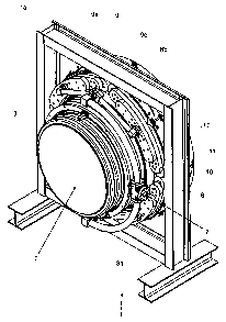
The item of the invention according to the first implementation example
from Figure 1 includes all of the ring-shaped covering head 1, which is
contained in a carrier frame 1 a. The covering head has a completely
circular central opening 2, through which the workpiece 3 can be moved.
The item being worked on is present, a corrugated pipe 3 of plastic, in
particular a polyolefin. The corrugated pipe has a smooth inner layer 3a
and a corrugated outer layer with corrugated peaks 3b and corrugated
valleys 3c. The corrugated pipe has an outer diameter d of about 1700 mm.
CA 02607712 2007-10-26
-14-
The drawings Figure 1 to 7 are each drawn to scale, so that the actual
measurements of the item can be deduced from appropriate scaling.
The workpiece 3 for setting a plastic layer is moved through opening 2 in
an axial direction, and thus according to the presentation in Figure 1 from
right to left.
The covering head 1 has a supply area 4, a distribution area 5, and a nozzle
area 6, each of which is set behind one another in the axial direction, and
each of which can be streamed through the heated and flowing plastic
material.
The supply area 4 comprises a primary main supply line 7, through which
a flowing plastic material that arrives from an extruder (not in the picture)
is filled into the device under pressure. In the supply area, this flow of
plastic material is divided into a total of 32 individual flows that are
essentially of the same size.
For this purpose, beginning from the main line 7, the supply area 4
comprises a first dividing piece 8, which divides the flow into two
secondary supply lines 8a, 8b. Each secondary supply line 8a, 8b flows to
dividing pieces 9, in which the flow is then divided into a total of four
tertiary supply lines 9a, 9b, 9c, 9d. In this fashion, a first distribution
area
is formed based on several times branched discrete, pipe-like lines 8a, 8b,
9a, 9b, 9c, 9c.
The first distribution area is followed by a second distribution area, in
which the flow of the plastic material is further divided. The second
CA 02607712 2007-10-26
- 15 -
distribution area consists of a number of plate elements 10 that extend in
peripheral direction. Each of the four tertiary supply lines 9a, 9b, 9c, 9d
flows into one of the four plate elements 10 of a first distribution level of
the second distribution area. Each of plate elements 10 comprises
distribution channel that is branched symmetrically in relation to the place
of the flow-in (not shown) in the form of a groove so that the number of
the plastic material flows is again doubled. Each of the plate elements 10
of the first level is attached, surface-wise, to a plate element 11 of a
second
level, and a corresponding arrangement of boreholes and groove-shaped
supply channels of the plate elements 11 results in another doubling of the
material flows. Each of the plate elements 11 of the second plate element
level is again attached to two of a total number of eight plate elements 12
of a third level, which analogously results in a last doubling of the total
number of the flow channels to a total number of 32 channels.
The last level of plate elements 12 is screwed down axially to a ring-
shaped distribution disk 13. A detailed illustration of the distribution disk
13 is shown in Figures 4 to 6. The distribution disk 13 comprises a number
of boreholes and/or threaded blind holes 14 to assembly the plate elements
12 adjacent on one side and the ring elements adjacent at the other side
(See subsequent description).
In addition, the distribution disk 13 comprises 32 axial channels 15
designed as boreholes that are arranged in a peripheral circle at a regular
angular distance and are connected to the 32 supply channels, designed as
grooves, of the last level of the plate elements 12. A punched hole 15a
with a thread coming in radial direction from outside flows into each of
the axial channels 15. These punched threaded holes 15a comprise setting
screws (not shown) that extend in the radial direction accordingly and are
accessible from outside. Depending on the position of the setting screw,
CA 02607712 2007-10-26
- 16-
the free cross-section of each of the axial channels 15 can be changed so
that the punched holes 15a together with setting screw have the function of
a throttle element.
An axial end face of the distribution disk 13 is structured on the side of the
distribution disk 13 that is positioned opposite the plate elements 12. The
structure comprises a wall 16 that is inclined in the cross-section as shown
in Figure 5, namely a wall 16 shaped in the shape of a conical segment,
and this wall 16 comprises a number of spiral-shaped grooves 17. Each of
the grooves 17 extends over an angular segment of about 35-40 degree
from the upper to the lower ends of the wall 16. Over this course, the axial
depth of the grooves levels off (See cross-section Figure 5). The 32
channels 15 end in the upper or radially external end area of the wall 16.
The inclination of the wall in relation to the radial direction (or the level
of
the drawing in Figure 4) is about 22 degree. In particular the values of the
angular segments of the course of the grooves 17 and the inclination of the
wall 16 are exemplary only and can assume other values depending on the
optimization of the device.
The end face of the distribution disk 13 that is structured with the wall 16
is adjacent to an essentially flat side of the upper ring element 17 that is
bolted to the distribution disk 13 by a bolt 17a so that the wall 16 a the
ring element 17 form a hollow space 18 (See the enlarged illustration in
Figure 7), which in the cross-section has essentially the form of a radially
inwards pointing acute triangle.
This hollow space 18 functionally forms the main part of the distribution
area 5 of the device. The plastic material that is fed through boreholes 15
to 32 circularly equally distributed points of entry flows through the
CA 02607712 2007-10-26
-17-
hollow space 18 essentially in radial direction from outside inwards, and,
in addition, the spiral-shaped grooves 17 create a flow component in the
peripheral direction. This design allows to properly homogenize the flow
of the plastic material, which was first discreetly distributed to 32 channels
in the peripheral direction.
The - in the radial direction - inner end of the hollow space 18 or the "top
of the triangle" into an angular gap 19 that extends in peripheral direction
and is uninterrupted, which defines the nozzle area 6 of the plastic material
flow.
The walls of the angular gap 19 are formed by the surfaces of a total of
three ring elements, namely the ring element 17 firmly bolted to the
distribution disk 13, an inner ring element 20 that is also attached to the
distribution disk 13 with bolt 20a extending beyond the distribution disk
13, and finally a front ring element 21 bolted to the upper ring element
with a bolt 21 a. Due to special forming of the opposite faces of the ring
elements 17, 20, 21 that are distanced so as to form the angular gap 19, the
gap assumes a course that is optimal for the flow of the plastic material:
The radially inner top of the hollow space 18 is adjacent to a first segment
19a that extends in the axial direction, that is, has the shape of a cylinder
jacket and has a constant flow cross-section. Then follows a second
segment 19b, which extends in the flow direction conically and in radial
direction inwards, and the two conical wall sections of the involved ring
elements 17, 20 have a different cone angle. Due to this design the gap
narrows down over its course so that its passage cross-section decreases
with the flow path more rapidly than in a linear fashion.
CA 02607712 2007-10-26
-18-
Adjacent to this double conical second segment 19b, there is arranged a
gate ring area 19c in the form of an axial segment, which has a reduced
cross-section area due to the distance between the walls.
The gate ring area 19c is followed by an exit gap 19d, which narrows
down similarly as the second segment 19b double conically and from
which the plastic material exits. The outer conical wall of the exit gap 19d
is formed by the front ring element 21. Spacer 21b in the form of inserted
spacing disks or a single spacing ring is located between the front ring
element 21 and the upper ring element 17. This design allows adjusting the
size of the exit gap 19d.
Adjacent to the exit gap 19d is an elastic scraper 22, which slides on the
undulated surface of the corrugated pipe 3. In addition, on the other end of
the device at the level of the supply area 4, there are provided further
scrapers 22 so that a closed volume is formed between the inner wall of
the device and the outer wall of the workpiece 3. Depending on the design,
the volume can also be closed off at one side by the exiting plastic material
line. The application of the plastic material can be influenced by targeted
application of pressure using provided gas channels (not shown). For
example, the gas pressure can be so set up in the closed volume areas
between the applied plastic material and the troughs of the corrugation rips
in order to achieve the desired concave, convex or flat surface in the area
of the ripple troughs after cooling off the plastic material.
Moreover, a number of tensioning screws 23 that are distributed along its
circumference and held in radial threaded boreholes of the upper ring exert
force upon the front ring element 21. In their entirety, the tensioning
screws 23 provide a tensioning element, which allows setting up an
CA 02607712 2007-10-26
- 19-
essentially radial deformation of the front ring element 20 so that the size
of the exit gap 19d can be changed in the direction of its circumference.
This design allows fine-tuning of the plastic material flow also during the
operation in order to guarantee a defined thickness of the applied coat that
is also constant over the entire area.
Furthermore, inside the opening 2 the device comprises a heating element
24, which is positioned at a short distance from the surface of the
workpiece 3. The heating element 24 warms up the surface of the
workpiece, in our case a corrugated pipe made of plastic material, and
especially melts down so that the applied plastic material creates a firm
connection with the surface. For this purpose, the workpiece and the
plastic material to be applied are ideally made of the same material or of
suitable pairs of materials.
A variant of the first embodiment is shown in Figure 8. Functionally
similar components are equipped with the same reference marks. A
substantial difference consists in the fact that the size of the angular gap
19
can be continuously changed by means of a thread, especially during the
actual operation. For this purpose, the upper ring element 17 is designed in
two parts, and the stationary part 17' is firmly attached to a differently
formed distribution disk 13' and the rest of the device. A movable part 17
is adjacent to the stationary part through an axial cylinder surface 24 and
can be shifted in the axial direction. The front ring element 21 is again
firmly connected to the movable ring element component 17 and, together
with the part 17, can thus be moved in axial direction in relation to the
stationary part 17' and an also firmly attached lower ring element 20. This
axial movement changes the size of the ring gap 19.
CA 02607712 2007-10-26
-20-
The movable part 17 is extending through guiding elements in the form of
pivots 25 and can move in axial direction. The ring element parts 17, 17',
which can move in relation to each other, comprise on its outer
circumference a first outer thread 26 and a second outer thread 27, and the
two threads have a slightly different lead. A ring nut 28 engages, with
accordingly different thread areas and at the same time, in the
corresponding threads 26, 27. Thus, by turning the ring nut 28, which
spans the device on its circumference, one can achieve an especially fine
setting of the ring gap 19 in the manner of a differential thread.
In the variant shown in Figure 8, the hollow space 18' of the distribution
area essentially extends in the axial direction and not in the radial
direction. However, the arrangement of a threaded adjustment element for
the ring gap 19 is possible also in the first embodiment without any
problem. For this purpose, for example, the upper ring element 17 can be
cut apart at the level of the end of the first segment 19 analogously to the
cylinder surface 24 and thus separated into a stationary and movable parts.
Another variant of the embodiment is shown in Figure 9. Compared to the
first embodiment, the only substantial change is the stepless/continuous
adjustability of the exit gap 19d, which is designed in a manner similar to
the adjusting option of the second embodiment.
In this design, the front ring element 21, which forms the radial outer wall
of the exit gap 19d, is not firmly bolted to the upper ring element 17 as in
the first embodiment, but can be moved in axial direction in relation to this
upper ring element 17. The movement is led by force over mutually
overlapping cylindrical guiding surfaces 29, and, just like in the second
embodiment (there, the cylinder surface 24) the overlapping and directly
CA 02607712 2007-10-26
-21-
touching of the cylinder surfaces 29 without any tolerance ensures the
sealing of the ring gap 19.
A differential ring nut 30 is arranged between the ring element 17 and the
front ring element 21. The ring nut 30 comprises an outer thread 31 that
extends in axial direction, which engages with a corresponding inner
thread on a reduced section of the ring element 17. An inner thread 32 of
the threaded nut concentric in relation to the outer thread 31 spans the
front ring element 21 and engages with a corresponding thread on its outer
surface.
In a similar design as in the second embodiment, the two threads 31, 32 of
the ring nut 30 comprises different leads so that the turning of the ring nut
by a certain angle induces an especially small and thus finely adjustable
axial movement of the front ring element 21 in relation to the upper ring
element 17 and thus of the lower or the inner ring element 22.
At least one axial groove with an inserted parallel key 33 is provided
between the upper ring element 17 and the front ring element 21. This
provides an axial guiding element, which prevents a simultaneous turning,
for example, of the front ring element 21, when the ring nut 30 is turned.
Based on the design arrangement of the differential ring nut 30 between
the front and upper ring elements, the arrangement of the tensioning
element or a number of radial tensioning screws 23 is changed. In the third
embodiment, the tensioning screws 23 do not press directly on the front
ring element 21, but rather on the upper ring element 17. The tensioning
screws 23 are bolted together or positioned against each other in a space
CA 02607712 2007-10-26
-22-
ring 34 that is separate from the upper ring element 17. The spacer ring 34
and the upper ring element 17 together correspond to the upper ring
element 17 from Figure 7, that is the first embodiment. On one of its sides,
the spacer ring is firmly bolted to the distribution disk 13 and thus forms a
wall of the hollow space 18. On its other end, the spacer ring 34 is firmly
bolted with bolts 34a to the upper ring element 17. Due to a suitable
design of these bolt connections, and because of the high pressing forces
of the tensioning screws 23, there exists a sufficient possibility of a radial
deformation of the upper ring element 17 and, through the adjacent surface
29, also of the front ring element 21 to allow a fine adjustment of the exit
gap in the peripheral direction. Just like in the first embodiment, here too,
the tensioning screws are accessible also during the production so that the
system can be fine-tuned during the production both using the ring nut 30
and by means of the tensioning screws 23.
Another preferred embodiment of the invention shown in Figure 10, the
distribution area 5 comprises a hollow space 118, which - in contrast to the
hollow space of the first embodiment - has a different form. This is
essentially a ring space, which is delineated by an inner lateral wall 118a
and an outer lateral wall 118b, each of which has the form of the surface of
a cone segment. The inner lateral wall 11 8a comprises a number of spiral-
shaped grooves 11 8e, which better distribute the plastic material that flows
through the hollow space 118 analogously to the preceding embodiments
of the invention.
The conical walls of the hollow space 118 are inclined inwards in the
radial direction and in the direction of the flow. The cone angle of the two
walls is of the same size, but not identical. The angle of the outer lateral
wall 11 8a relatively to the axial direction is about 22 degrees and the angle
of the outer wall is greater by about 2.5 degrees. Therefore, in the floe
CA 02607712 2007-10-26
- 23 -
direction of the plastic material, the distance between the lateral walls
118a, 118b somewhat increases.
Analogously to the first embodiment, the hollow space 118 is connected to
the supply area 4 through a total of 32 supply channels 115. The supply
area 4 is designed exactly as in the first embodiment. The supply channels
115 are designed as boreholes in a ring-shaped inner distribution part 113,
according to which the inner lateral wall 118a of the hollow space 118 is
formed. Also analogously to the first embodiment, the punched holes 115a
are oriented in radial direction from outside towards the channels 115 in
order to allow setting up the flowing cross-section of the individual
channels by means of inserted adjustment screws.
The inner distribution part 113 is firmly bolted to an outer distribution part
11 7a, according to which the outer lateral walls 118b of the hollow space
118 are formed.
The hollow space 118, which mainly serves the purpose of homogenizing
the flow of plastic material that is conducted separated through the 32
channels 115, flows into a ring gap 119. This is first designed between an
outer ring element 117 and an inner ring element 112. The ring element
117 can be adjusted in radial direction by means of an adjusting elements
designed as tensioning screws 117b, and this can be done - depending on
the requirements - by offsetting and/or by elastic deformation. In axial
direction, the ring element 117 can be firmly bolted to the outer
distribution part 117a using clamping screws 117c, and these screws are
somewhat loosened for the purpose of setting up the outer ring element
117.
CA 02607712 2007-10-26
-24-
The inner ring element 120 is firmly connected to the inner distribution
element 113 by means of screws 120a that penetrate the inner distribution
element 113 in axial direction.
In the example shown in Figure 10, the outer ring element 117 is followed
by another ring element 121, and the exit-side end 119d of the angular gap
119 is designed between the additional ring element 121 and the inner ring
element 120. The additional ring element 121 can be adjusted in radial
direction by means of setting elements 123 designed as tensioning screws
123, and the tensioning screws 123 are retained or supported in the outer
ring element 117 in a thread. This adds to the adjustability of the angular
gaps 119 in its exit area 119d.
The corrugated pipe 103 shown in the illustration in Figure 10 has an inner
diameter of 762 mm (30 inches, diameter up to the inner wall 103 coated
with corrugated web). The diameter of the angular gap 119 at its exit-side
end is about 890 mm. The smallest diameter of the hollow space 118,
which must be measured at its exit-side end, is about 1,870 mm. This
results in a relatively long course of the angular gap 119 so that the
additional ring element is advantageous for adjustment.
In their entirety, the inner ring element 120, the outer ring element 117 and
the additional ring element 121 form a set of ring elements, which - with
other components of the device left unchanged - can be exchanged like a
module.
Figure 11 shows the same device as in Figure 10, where, however, the
shown first set of ring elements 117, 121, 121 has been replaced with
CA 02607712 2007-10-26
-25-
another, a second set of ring elements 117', 120'. The inner diameter of the
exit gap 119d is substantially greater, namely up to about 1,800 mm. The
pipe 103' is a corrugated pipe with an inner diameter of 60 inches. Due to
the shorter angular gap 119', one of the ring elements and one adjusting
option can be eliminated so that the nozzle area, that is the angular gap
119 is now formed only by one inner ring element 120' and an outer ring
element 117'.
Depending on the set of ring elements arranged in the distribution area
104, a part made of plastic material can be coated with a different
diameter. In the present embodiment, as shown, the endeavor is to cover at
least the area of about 30 inches up to about 60 inches inner diameter of
the corrugated pipe, for which only the sets of ring elements need to be
exchanged.