Note: Descriptions are shown in the official language in which they were submitted.
CA 02607722 2007-11-07
WO 2006/133073
PCT/US2006/021704
DRAINAGE SYSTEM FOR USE IN
BUILDING CONSTRUCTION
FIELD OF THE INVENTION
This invention generally relates to systems, such as are used in association
with cavity wall construction, which function to reduce or prevent water
damage
entering or trapped in the wall. More particularly, the invention is directed
to a
system which includes flashing elements which function to direct water from a
wall
in which it is installed, drainage elements associated with the flashing
elements to
direct water from the flashing and additional elements to prevent mortar and
debris
from interfering with drainage.
BACKGROUND OF THE INVENTION
The present invention is at least applicable to so-called cavity wall
construction. Cavity walls may be composed of two wythes of masonry, usually
brick and concrete block, which may be secured together by, for example, metal
ties
and spaced apart by a cavity between the wythes. The inner wall may be
constructed from wood with an inner surface of drywall, structural clay tile,
vertical
stacks of mortared bricks or blocks, or a shear concrete surface, for example.
The
outer wall is typically formed of bricks and held together by mortar. A space,
or
cavity, exists between the two walls, in part for drainage purposes and which
may
also be partially filled with insulation. It is applicant's understanding that
the Brick
Institute defines a "cavity wall" as having a space greater than about 2
inches but
not more than 4 inches between the wythes. However, the present invention is
useful in spaces between inner and outer walls spaced apart less than 2
inches,
and more than 4 inches.
In conventional cavity wall construction, flashing is typically installed atop
the
foundation and weep holes are formed to collect moisture and drain the cavity.
Moisture may penetrate the exterior wythe of the wall through a number of
places,
including top caps, copings, sills, windows, and may penetrate the wall itself
through
1
CA 02607722 2007-11-07
WO 2006/133073
PCT/US2006/021704
cracks or weaknesses, for example. It is well established that moisture is
undesirable in brick or similar wall construction. The presence of water in
freezing
temperatures may cause cracks in the wall when water expands as it freezes.
Trapped water may cause discolorations and other problems, and may even
migrate into the dwelling. Another hazard of failing to deal with water is the
formation of mold. It is widely accepted that mold growth can damage a
building or
render the building uninhabitable for various reasons. These reasons include a
dangerous situation where the mold growth produces toxins and/or allergens
sufficient to sicken inhabitants.
To overcome the problems associated with trapped water, weep holes are
commonly included along the base of the outer side of and in the lowermost
course
of bricks or other masonry units. The weep holes allow water to pass from
inside
the wall. Also, the weep holes permit water to drain outside the wall
structure. A
flashing disposed in the wall cavity directs the collected water toward the
weep
holes.
A problem of cavity wall construction occurs during construction of a cavity
wall, when excess mortar and other debris falls into the cavity. When the
bricks or
blocks are stacked during the erection of the wall, for example, mortar
droppings
are squeezed into the cavity. The excess mortar materials, as well as other
debris,
such as insulation, drops to the base of the cavity, and can block weep holes.
The
same problem can reduce the effectiveness of flashing. To address this
problem,
inserts, generically be referred to as a cavity mortar collection device, may
be used
in the cavity. Successful devices designed to address the problem of moisture
and
debris in cavity wall construction are shown, for example, in US Patent Re.
36,676,
incorporated herein by reference.
A major consideration of construction is, of course, cost. A substantial cost
2
CA 02607722 2013-09-19
may be associated with the time it takes for installation of some flashing
devices and
cavity inserts. The complexity of some of these moisture and debris control
solutions can be a substantial factor adding cost to the construction of
cavity walls.
The present invention is directed to solving one or more of the problems
discussed
above, in a novel and simple manner.
SUMMARY OF THE INVENTION
In accordance with the invention, there is provided a flashing and drainage
system for use in cavity wall construction, including a flashing member, which
is
sized and shaped to be received within a cavity of the wall and over the base
member. The flashing member includes a lower flashing portion which is
oriented
generally horizontally when atop a foundation portion of the wall and an upper
flashing portion which is oriented generally vertically, and preferably
snugly, within
the cavity of the wall. A plurality of weep tabs are positioned on the lower
flashing
portion and spaced apart to correspond to weep holes formed through the wall
and a
plurality of porous bodies are positioned on the upper flashing portion. Each
of the
plurality of porous bodies have a porosity sufficient to permit water to pass
therethrough but substantially insufficient to permit mortar and debris to
pass
therethrough, each of the plurality of porous bodies being positioned to
protect a
corresponding one of the plurality of weep tabs.
In one broad aspect, the invention pertains to a flashing and drainage system
for use in cavity wall construction, comprising a longitudinal base member,
and a
flashing member sized and shaped to be received within a cavity of the wall
and
over the base member. The flashing member includes a lower flashing portion
which is oriented generally horizontally atop a foundation portion of the wall
and an
upper flashing portion which is oriented generally vertically within the
cavity of the
wall. A plurality of weep are tabs positioned on the lower flashing portion
and
spaced apart to correspond to weep holes formed through the wall. The
plurality of
weep tabs extend from a horizontally oriented common body portion formed of
the
3
CA 02607722 2013-09-19
,
same material as the weep tabs. A plurality of porous bodies are positioned on
the
upper flashing portion and are separate from the common body portion, each of
the
plurality of porous bodies having a porosity sufficient to permit water to
pass
therethrough but substantially insufficient to permit mortar and debris to
pass
therethrough. Each of the plurality of porous bodies are positioned to protect
a
corresponding one of the plurality of weep tabs.
Other aspects of the flashing and drainage system provide a drip edge formed
at a distal end of the lower flashing portion. The system may further include
a base
portion, which is sized and shaped to fit underneath the flashing member. A
pair of
end dams may be formed at opposite ends of the flashing member. One or more
reinforcing member may be attached adjacent an upper edge of the upper
flashing
portion to reinforce the upper flashing portion. Each of the plurality of weep
tabs may be provided as individual strips of material. The plurality of weep
tabs
3a
CA 02607722 2007-11-07
WO 2006/133073
PCT/US2006/021704
may also be attached at a proximal end to a common body portion of material.
The
system may also include further a plurality of corner pieces sized and shaped
to
cover a corner of a foundation underneath a cavity wall construct and adapted
to
abut the base portion to form a base for a plurality of the flashing members
when
the flashing members are placed end to end over the base portions and the
corner
pieces. The corner pieces may be both outer corner pieces and outer corner
pieces.
Further features and advantages of the invention will be readily apparent
from the specification and from the drawings.
BRIEF DESCRIPTION OF THE DRAWINGS
Fig. 1 shows a conventional cavity wall construction in cross section;
Fig. 2 shows a perspective view of a flashing and drainage assembly
according to one embodiment of the invention;
Fig. 3 shows a perspective view of a flashing and drainage assembly
according to another embodiment of the invention;
Fig. 4 shows a cross sectional view of an embodiment of the invention;
Fig. 5 shows a cross sectional view of another embodiment of the invention;
Fig. 6A shows a cross sectional view of yet another embodiment of the
invention;
Fig. 6B shows a cross sectional view of yet another embodiment of the
invention;
Fig. 7 shows a cross sectional view of yet another embodiment of the
invention;
Fig. 8 shows a corner assembly usable with any of the embodiments shown
in Figs. 2-7; and
4
CA 02607722 2007-11-07
WO 2006/133073
PCT/US2006/021704
Fig. 9 shows alternate embodiments of a mesh body.
DETAILED DESCRIPTION OF THE INVENTION
A cavity wall 10, as shown in Fig. 1 may consist of two wythes 12, 14 of
masonry built upon a foundation 24. The two wythes are separated by an air
space
16. The interior wythe (the inner wall) 12 may be brick, hollow brick,
structural clay
tile, wood or hollow or solid concrete masonry units, for example. The
exterior
wythe 14 (the outer wall) may be brick. A cavity 16 is defined between the two
wythes, i.e., between inner or interior faces 20, 22 of outer and inner walls
14, 12
respectively. The cavity 16 may be either provided with insulation or left
open as air
space. The cavity 16 has a typical width of about 2 to about 4 1/2 inches, but
could
be smaller, although non-standard. Of course, the wall 10 may be brick or
block
construction and may have components formed from wood, stud, steel stud and
other construction techniques, materials and methods, which include a cavity
16 or
the equivalent.
As mentioned above, a common problem associated with a cavity wall
construction is how to allow moisture, as from seepage or condensation, for
example, to pass from the cavity 16 to outside the wall 10. Weep holes 18 are
formed to provide an unobstructed opening passing from the cavity to the
outside of
the wall. Generally, the weep holes 18 will be placed approximately one to two
feet
apart at the base of the outer wall 14. It has been found that moisture
collecting in
the cavity tends to run down the inside face 20 of the outer wall 14.
In the course of construction of a cavity wall 10, mortar and other debris
(not
shown will commonly fall into the cavity 16 between the inner wall 12 and
outer wall
14. If enough mortar builds up around the weep holes 18, or if it simply
lodges in
the weep holes, the weep holes will become plugged, causing water to pond
5
CA 02607722 2007-11-07
WO 2006/133073
PCT/US2006/021704
between the walls 12, 14. The water can then leak into the foundation 24,
building
structure, or cause cracking, deterioration and/or discoloration of the walls.
Referring to Figs. 2 and 3, a drainage system 30 is illustrated for use in
connection with cavity wall construction. The drainage system 30 includes
three
main parts, which will be described in detail below, with a number of
additional
elements optionally associated therewith and forming various embodiments of
the
invention. The system 30 includes flashing member 32. The flashing member 32
is
provided with one or more weep tabs 34. The flashing member 32 also includes
one or more vertical mesh members 36.
The flashing member 32 may be any conventional flashing material, for
example stainless steel, cold-rolled copper, lead coated copper, galvanized
steel,
copper laminates and other metals, for example, aluminum, EPDM (man-made
rubber), rubberized asphalt, polyvinyl chloride (PVC) and other plastics and
composite materials. Preferably, the flashing member 32 is formed of modified
bitumen and more preferably, includes a "peel-and-stick" type adhesive and
protective backing sheet (not shown) on a backside 38 thereof.
The flashing member 32 shown is rectangular and may advantageously be
about 5-7 feet in length and includes a lower flashing portion 40 and a more
upright
upper flashing portion 42. The flashing member 32 may be other lengths as
needed
or desired. The lower flashing portion 40 is positioned over the top of a
foundation
of a building or the like, or a lower course of bricks, or blocks and so on.
The upper
flashing portion 42 is positioned generally vertically in a wall cavity 16 and
spaced
from an inside face 20 of the outer wythe 14 and in contact with an inner face
22 of
the inner wythe 12 and keep spaced from the inside face 20 of the outer wythe
14
by pressure between the brick of the outer wythe and the mesh material 36.
The weep tabs 34 are positioned atop the lower flashing portion and are
6
CA 02607722 2007-11-07
WO 2006/133073
PCT/US2006/021704
sized, shaped and spaced to extend through the weep holes 18 (Fig. 1) of wall
10.
The tabs 34 are formed of a porous and/or wicking material, like an open mesh
plastic, cotton, wool or hemp material capable of functioning to transmit
water from
atop the flashing 32 and out the weep holes 18 (Fig. 1). In the illustrated
embodiment, the weep tabs 34 are separate strips of material.
The vertical mesh bodies 36 are positioned on the upper flashing portions 42
and spaced in a manner to deflect and/or prevent debris and mortar from
occluding
the tabs 34. Furthermore, the depth of the vertical bodies 36 are provided so
as to
space the vertical flashing portion 42 from the inner face 20 of the outer
wall 14 and
generally adjacent the inner face 22 of the inner wall 12. In one example, the
vertical bodies 36 are about 1 inch thick.
The vertical bodies 36 may be formed of any suitable fibroid water permeable
material 28. The material of the vertical bodies 36 should resist compression
when
under the weight of debris and mortar and continue to permit water to pass
through.
In this embodiment, each body 36 has a generally rectangular shape that will
rest
flush against the wall 14. The width of the body 36 may roughly determined by
or
correspond to the width of the cavity 16. Other shapes, which will be shown in
more
detail below include square, trapezoid, triangular, inverted trapezoid and
triangular,
hourglass and wineglass shaped as well as other shapes, for example, smooth or
curved shapes.
The body 36 is preferably composed of non-absorbent plastic, such as, for
example, the filament-type plastic used to surface walk-off mats. These
materials
are preferred because they are water-impervious, relatively inexpensive and
can be
formed into dividable blocks or sheets. A quantity of one or more of these
materials
can be formed into a mass of random fibers with a density which is sufficient
to
catch and support mortar and other debris thereon without significant
collapse, but
7
CA 02607722 2007-11-07
WO 2006/133073
PCT/US2006/021704
allow water to pass freely therethrough. An objective of the vertical mesh
bodies 36
is to separate clumps of mortar and debris and direct the mortar and debris
away
from the weep tabs 34 and ultimately prevent mortar and debris from preventing
the
egress of water from within the cavity 16.
The porosity of the body 36 made from the fibrous material can be quite
varied, so long as it effectively serves to strain out the mortar and debris
before it
reaches the weep holes 16. Most mortar and debris will be quite large, i.e.,
greater
than 1/8 or 1/16 of an inch or clearly visible to the naked eye, so an amount
of
porosity sufficient to catch such relatively large particulate matter will
suffice to
prevent plugging of the weep holes 16.
The drainage system 30 of this invention may simply be positioned on the
wall foundation in cavity 16 without the need of any fixation device. In the
alternate,
the device 30 may be caulked in place. In yet another embodiment, the flashing
backside 38 may be supplied with a pressure sensitive adhesive, which is
protected
by a backing sheet (not shown). Pressure sensitive adhesives are well known.
The drainage system 30 illustrated includes other features. The lower
flashing portion 40 may include a drip edge 44 at a leading edge thereof. The
drip
edge 44 is preferably stainless steel, although other suitable materials are
contemplated by the invention, such as copper, aluminum, plastic, elastomeric
materials, and so on. The drip edge 44 may be a strip of material, such as
stainless
steel bonded or otherwise connected to the bottom of the lower flashing
portion 40
or may be an extended lip formed from the flashing portion itself. The lower
edge
46 of the drip edge 44 is turned down vertically, preferably about 75 degrees,
and
may be plain or rolled back to provide a finished edge.
The drainage system 30 may include a base 48, which may function as a pan
or the like, underneath the flashing 32, which includes a horizontal base
portion 50
8
CA 02607722 2013-09-11
and a back leg portion 52. The horizontal base portion 52 is rectangular and
is
positioned underneath the lower flashing portion 40 and may extend to a
position
adjacent the drip edge 44. The back leg 52, which preferably is inclined about
30
degrees, forms a dam at the back edge thereof and also causes the flashing
member 32 to be inclined at the juncture of the lower and upper portions 40,
42, so
as to encourage the egress of water from the flashing and out weep holes 16.
The
back leg 52 prevents water that infiltrates past the flashing 32 to enter the
foundation. As will be shown in more detail below, the back leg 52 may be an
angled piece, a separate piece or a triangular piece to produce a dam effect
in the
base 48 and alternately in the base and flashing 32. In a preferred
embodiment, the
base 46 and drip edge 44 are formed from a single sheet of material (see Fig.
6B),
but also may be separate (see Fig. 6A).
At a top edge 54 of the upper portion 42 of flashing 32 one or more rigid
horizontal bars 56 may be optionally provided to enhance the rigidity of the
flashing
upper portion. The horizontal bars 56 function to prevent the upper portion 42
of the
flashing 32 from drooping or being dislodged from against the inner surface 22
of
inner wall 12. The bar 56 may be cylindrical or rectangular, for example, and
affixed
to the upper portion 42 by adhesives or fasteners, like screws. The bar 56 may
be
provided in a pocket or hem of the flashing material and also may be affixed
to the
inside surface 22 of the inner wall 12 by screws, anchors, or other fasteners,
for
example.
A pair of end dams 58 is formed at opposite ends of the lower portion 40 of
the flashing 32 to raise the end sections of the flashing. Like the back leg
62, the
end dams 58 function to direct water off the flashing and away from the
foundation.
The end dams 58 may be formed by turning edges of the flashing material 40
upwardly or inserting some thickness of material underneath the flashing.
9
CA 02607722 2007-11-07
WO 2006/133073
PCT/US2006/021704
An extension 60 of the base 48 is provided for joining together in an end-to-
end fashion multiple units 30. The extension 60 is preferably about 4 inches
long,
but may be anywhere from about 1 inch to 6 inches or more. When adjacent units
30 are joined, the ends of the flashing 32 are covered with a waterproof tape-
like
material, like a 4-inch strip of modified bitumen to provide a seal over the
joint. The
base extension 60 ensures that any water coming through the joint will be
directed
away from the wall.
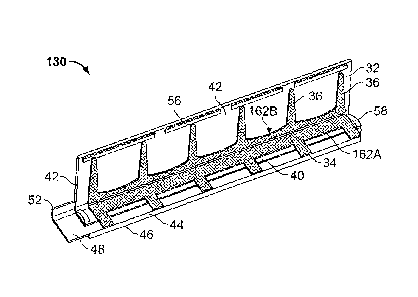
The device 130 shown in Fig. 3 is similar to that shown in Fig. 2 except that
the weep tabs 34 are all formed and extend from a common body portion 162A
formed of the same material as the weep tabs. The common body portion 162A is
positioned on the flashing 32 on the lower panel 40 thereof so as to align the
tabs
34 with vertical mesh towers 36, which themselves are positioned in a spaced
configuration on the vertical or upper panel of the flashing. Similarly, the
vertical
mesh bodies 36 may be joined at lower edges thereof from a common body portion
162B.
Fig. 4 shows one embodiment of the invention in a more basic form. The
device 30 includes an L-shaped flashing member 32. The flashing member 32
includes a lower flashing portion 40 which is generally horizontal and is
sized and
shaped to fit over the top of a foundation or the like. An upper flashing
portion 42
extends upwardly from a back edge of the lower flashing portion 40 and is
adapted,
sized and shaped to fit within a wall cavity and lean against, be adhered to
or
fastened to the face of an interior wall 22 facing the cavity 16.
One or more weep tabs 34 are positioned on the lower flashing portion 40
and spaced and/or positioned to cooperate with weep holes 18 in an outer wythe
14
of wall 10 (Fig. 1). A vertical mesh body 36 is positioned on the upper
flashing
portion 42 to cooperate with each of the weep tabs 34 and prevent debris and
CA 02607722 2007-11-07
WO 2006/133073
PCT/US2006/021704
mortar from occluding the effectiveness of the weep tabs from removing water
from
atop the flashing 32. The vertical mesh body 36 also functions to space the
upper
flashing portion 42 from an inner face 20 of outer wall 14 and against the
wall face
22 (Fig. 1).
Fig. 5 shows the device 30 of Fig. 4 with the addition of a drip edge 44. As
above, the drip edge 44 may be a separate piece formed of a material like
stainless
steel, modified bitumen or the equivalent, or may be a turned down lip of the
lower
flashing portion 40 of the flashing member 32.
Fig. 6A shows the device 30 of Fig. 4 with the addition of base 48. Like the
drip edge 44 the base 48 is preferably made of a water impervious material,
like
stainless steel or an equivalent thereof. The base 48 is positioned underneath
the
lower flashing portion 40 and drip edge 46. The base 48 includes a flat
horizontal
portion 50 and a rear leg 52 which functions to elevate the rear section of
the lower
flashing portion 40 and direct water thereon towards and out through weep
holes 18
in the outer wall 14 (Fig. 1). In this embodiment, the distal end 46 of the
drip edge
44 is curved back to provide a smooth edge and resist the tendency for water
to
reenter the foundation 24 (Fig. 1) once arriving at the drip edge.
Fig. 6B shows the device 30 of Fig. 6A with the addition of a combined base
48 and drip edge 44 forming a tray (combined pan or base 48 and drip edge 44).
As above, the base 48 and drip edge 44 are preferably made of a water
impervious
material, like stainless steel or an equivalent thereof. The unitary or
combined base
48 and drip edge 44 is positioned underneath the lower flashing portion 40.
The
base 48 includes a flat horizontal portion 50 and a rear leg 52 which
functions to
elevate the rear section of the lower flashing portion 40 and direct water
thereon
towards and out through weep holes 18 in the outer wall 14 (Fig. 1). The leg
52
may be angled at about 30 degrees. The distal end 46 of the drip edge 44 is
angled
11
CA 02607722 2007-11-07
WO 2006/133073
PCT/US2006/021704
almost vertically to provide a compact profile against the outer wall and urge
water
off of the base 48.
Fig. 7 shows the device 30 of Fig. 4 with the addition of base 48 and drip
edge 44 underneath flashing 32. The base 48 includes a flat horizontal portion
50
and a rear leg 152, which is different from the leg 52 of Fig. 6 in that the
leg has a
triangular shape instead of being an upturned edge. It functions similarly to
that
shown in Fig. 6 to elevate the rear section of the lower flashing portion 40
and direct
water thereon towards and out through weep holes 18 in the outer wall 14 (Fig.
1).
Fig. 8 shows a corner piece 70 for use with device 30 (Fig. 2) of the present
invention. The corner piece 70 may be made of any suitable material, for
example,
stainless steel, copper, aluminum, plastic, modified bitumen, and so on. The
corner
piece has three main sections, namely a corner drip edge 72, which is turned
down,
a horizontal main corner portion 74 and a back corner dam 76 which is raised
up
relative to the main portion. Extensions 78 of the main portion 74 extend
under or
overlap with section 60 (see Figs 2 and 3), base 40 or flashing 32 lower
portion 40
when the flashing device 30 is laid over the corner piece 70. A corresponding
inside corner piece (not shown) will also include similar features and will be
used on
inside corners of the cavity wall.
Fig. 9 illustrates several embodiments of the mesh bodies 36. In particular,
the mesh bodies may be an inverted wedge shape (inverted trapezoidal) 80, a
wedge shape (trapezoidal) 82, wine glass shape 84 and triangular 86, for
example.
In use and referring to at least Figs 1, 2 and 8, the back corner dam 76
portion of the corner piece 70 is positioned against the inner wall 12 and
atop the
foundation 24 (Fig. 1) or the like at a corner thereof with the drip edge 72
extending
outwardly over the outermost edge of the corner of the foundation 24. The
corner
piece 70 may be fixed in position with caulk or the like or any other suitable
method.
12
CA 02607722 2007-11-07
WO 2006/133073
PCT/US2006/021704
The base 48 is positioned in an overlapping relationship with the corner piece
70
atop the foundation 24 and similarly sealed and/or fixed into position with
caulk or
the like.
The flashing member 32, which may be in an initial folded condition, i.e.,
with
tabs 34 and mesh 36 inside the folded upper and lower flashing portions 42,
40, is
positioned longitudinally along the foundation 24 over the base 48. It will be
understood that the base 48 may be provided pre-attached to the underside of
the
lower flashing portion 40 or separately. Initially, the lower flashing portion
40 is
placed on the foundation and then the upper flashing portion 42 is raised
against
wall 12. If a backing material (not shown) is used to protect a pressure
sensitive
adhesive on the flashing device 30, it is removed just prior to positioning
the
flashing 32. Furthermore, the flashing member 32 may be secured in place with
adhesive, fasteners, caulk and so on or held in place by the weight of the
device
until bricks of the wall 10 are put into place.
The weep tabs 324 are aligned with the position of the weep holes 18 of the
outer wall 14. Adjacent flashing units 30 or flashing device 32 are sealed at
abutting portions, i.e., at the end dams 58 to prevent or reduce leakage at
the joints
between units.
13