Note: Descriptions are shown in the official language in which they were submitted.
CA 02608523 2007-11-14
WO 2006/122928 PCT/EP2006/062327
"Method for manufacturing at least a surface layer of a multilayered
trim part"
The present invention relates to a method for manufacturing
at least a surface layer of a multilayered trim part for attachment to a
structure of a vehicle, which surface layer has a front side formed at least
partially by a first surface portion, which has a first colour, and by a
second surface portion, which is situated at least partially against the first
surface portion and which has a second colour different from the first
colour. The surface layer is in other words a two- or multicolour surface
layer. The method for manufacturing such a surface layer is a moulding
method wherein a first layer forming the first surface portion is produced
against a first portion of a mould surface while leaving a second portion of
the mould surface free for producing, in a next step, a second layer
forming the second surface portion against the second portion of the
mould surface and at least partially also against the back of the first layer.
The multilayered trim part is for example a dashboard, a
door panel, a console or another interior trim part of an automotive
vehicle. Usually it consists of the surface layer bonded by means of an
intermediate foam layer to a rigid substrate layer. The surface layer may
consist of an elastomeric skin layer either or not provided with a thinner
coloured layer, in particular a paint layer. In the method according to the
invention the skin layer is moulded against a mould surface. If it is
covered by an additional coloured coating layer, this coating layer is first
applied, as an in-mould coating, onto the mould surface.
The surface layer can be made for example by means of a
spray or a pouring process wherein a curable skin material, in particular a
CA 02608523 2007-11-14
WO 2006/122928 PCT/EP2006/062327
-2-
polyurethane reactive mixture, is sprayed or poured in a liquid state onto
the mould surface. Such a method is disclosed in EP-B-0 804 327. In this
known method a first layer forming material, more particularly a
polyurethane reactive mixture having a first colour, is sprayed first onto a
first portion of the mould surface while shielding off a second portion of
the mould surface by means of a mask. In a next step, the mask is
removed and a second layer forming material, again a polyurethane
reactive mixture but having a second colour different from the first colour,
is sprayed onto the second portion of the mould surface and partially onto
the back of the previously sprayed polyurethane layer. The first layer
forming material thus has an edge which is situated underneath the layer
of the second layer forming material and which defines the colour
transition between the first and the second surface portion of the surface
layer.
A drawback of this known method is that the transition
between the two colours is not always sufficiently sharp, due to sputtering
or scattering of the polyurethane reactive mixture underneath the mask.
EP-B-0 804 327 therefore discloses to provide the transition between the
two colours onto an upstanding ridge of the mould surface in order to
hide the transition zone between the two colours from view. The actual
colour transition is then indeed located in a groove in the surface layer of
the trim part. However, due to the width of the groove, it still remains
somewhat visible so that a need remains to achieve a sharp transition
between the different colours.
DE-A-100 62 825 provides an improvement of the method
disclosed in EP-B-0 804 327. In the method disclosed in this German
patent application, the surface layer is produced by spraying a first paint
layer onto a first portion of the mould surface, by spraying a second paint
layer onto a second portion of the mould surface and partially onto the
back of the first paint layer, by pouring a polyurethane reactive mixture
CA 02608523 2007-11-14
WO 2006/122928 PCT/EP2006/062327
-3-
onto the back of both paint layers and by closing the mould to allow the
polyurethane reactive mixture to cure in a closed mould. When spraying
the first paint layer, the second portion of the mould surface is covered by
means of a mask. Notwithstanding the fact that a mask is used to cover
the second portion of the mould surface and hence to define the edge of
the first paint layer, DE-A-100 62 825 discloses it is difficult to achieve a
clear and sharp dividing line between the two colours. DE-A-100 62 825
therefore also describes to produce the transition between the two
colours on top of an upstanding ridge. The improvement proposed by DE-
A-100 62 825 consists in reducing the width of the thus obtained groove
on the visible side of the surface layer. This is achieved by transferring
the surface layer to a second mould wherein the upstanding ridge is
replaced by a thin upstanding sheet. In this second mould a foam layer is
moulded onto the back of the surface layer. A drawback of this method is
that it does not allow a direct back-foaming process and that a second,
expensive mould is therefore always required to perform the backfoaming
process.
Another method making use of the mask technology to
produce a multicoloured trim part, is disclosed in US-A-2004/0099988. In
this method, a first paint layer is sprayed onto a first portion of the mould
surface and a second paint layer on a second portion of the mould
surface, which was covered with a magnetically securing mask when
spraying the first paint layer. A third material, usually a polyurethane
material, is then applied, usually sprayed, over the first and second paint
layers to form a backing layer. In this known method the transition
between the two colours is also produced on top of an upstanding ridge
to hide the colour transition from view.
A drawback of the prior art methods set forth hereabove is
that, due to the use of a mask, defects arise at the transition or parting
line between the different colours, i.e. either some of the first layer
CA 02608523 2007-11-14
WO 2006/122928 PCT/EP2006/062327
-4-
forming material will arrive onto the second mould surface portion when
removing the mask, this is the so-called bridging problem, or, when such
bridging is avoided by maintaining a distance between the mould surface
and the edge of the mask, some of the first layer forming material will
arrive underneath the edge of the mask causing a scattered transition
zone between the different colours. The use of upstanding ridges on the
mould surface, to hide these colour transition zones from view, involves
an important limitation of the design possibilities. Moreover, the use of
upstanding ridges do not enable flat colour transitions. A further
drawback of the prior art methods is that the used mask technology is
critical and complex. In order to get the colour transition line as good as
possible, the mask geometry has to be tailored accurately to the three-
dimensional shape of the mould surface and in particular to the geometry
of the upstanding ridges. Any deviation in both geometries will be
translated in inaccurate colour transitions.
A method wherein a surface layer for a trim part is produced
without the use of a mask is disclosed in US-A-5 328 349. In this known
method a multicoloured slush skin is produced by a powder-slush
process. According to this US patent, masking techniques can be used
for producing multicoloured slush skins but it has been shown in actuality
that the separating seam looks untidy to the eye. In the disclosed
method, the entire mould surface is therefore first covered with a first
thermoplastic material, a portion of produced slush skin is cut out and
removed from the mould surface and a second thermoplastic material is
moulded onto the free mould surface and onto the back of the first
thermoplastic material. An important drawback of such a method is that it
is only applicable for thermoplastic materials. Moreover, it is a quite
complex process and, in the disclosed method, the actual colour
transition has still to be produced on top of an upstanding edge.
CA 02608523 2007-11-14
WO 2006/122928 PCT/EP2006/062327
-5-
Other methods which are only applicable for thermoplastic
materials are disclosed in JP 59142112 and in US-A-5 073 325. In these
known methods a pattern recessed in the mould surface is first filled up
with a thermoplastic material. In a next step, the entire mould surface is
covered with a second thermoplastic material so that the front side of this
second thermoplastic material has a decorative feature formed by the first
thermoplastic material. A drawback of these methods is also that the first
thermoplastic material has to be applied always in a pattern recessed in
the mould surface and, moreover, after having applied the first material in
the recessed pattern, any excess of material outside the recessed pattern
has to be removed. A further drawback of these known methods are the
limited design possibilities due to the fact that the second thermoplastic
material extends always on both sides of the decorative feature. It is thus
for example not possible to produce a surface layer consisting of two
main surface area's of different colours.
An object of the present invention is now to provide a new
method which enables to obtain a qualitative transition between the
different colours without having to hide the actual colour transition in a
groove or in any other way from view and without having to cut out a
portion of the first layer forming material before applying the second layer
forming material onto the mould surface.
The method according to the invention is characterised
hereto in that when applying the first layer forming material onto the first
portion of the mould surface, at least a portion of the edge of the layer of
the first layer forming material, which will be situated on the mould
surface underneath the layer of the second layer forming material, is
formed without a mask. Moreover, a layer of a third layer forming
material, which is hardenable and has a third colour which is different
from the second colour, is applied onto a third portion of the mould
surface, which is separated at least locally by the first portion of the
CA 02608523 2007-11-14
WO 2006/122928 PCT/EP2006/062327
-6-
mould surface from the second portion thereof, and the layer of the third
layer forming material is allowed to harden to produce a third layer
forming a third surface portion of the surface layer which is separated at
least locally by the first surface portion of the surface layer from the
second surface portion thereof, the layer of the third layer forming
material being either applied onto the mould surface before applying the
layer of the first layer forming material thereon, in which case the first
layer forming material is applied at least partially onto the back of the
layer of the third layer forming material, or after having applied the layer
of the first layer forming material thereon, in which case the third layer
forming material is applied at least partially onto the back of the layer of
the first layer forming material.
In the prior art methods wherein the second portion of the
mould surface is kept free of the first layer forming material when
applying this material onto the first portion of the mould surface, use is
always made of a mask for shielding off the second portion of the mould
surface and for defining the edge of the first layer.
In a first aspect of the invention, the first colour is
substantially the same as the third colour. In this way, there is no visible
difference between the first and the third surface portion. An advantage of
this embodiment is that only a quite narrow strip of the first layer forming
material has to be applied, which can be done quite accurately, in
particular so that a visually sharp edge can be obtained, without
intervention of a mask, when applying the first layer forming material.
Since the required visually sharp edge between the two colours is already
achieved by means of the first layer forming material, the third layer
forming material can be applied easily over a larger surface (for example
by spraying).
In a second aspect of the invention, it has been found that
the disadvantages of the prior art methods can be obviated by applying
CA 02608523 2007-11-14
WO 2006/122928 PCT/EP2006/062327
-7-
the first layer forming material in such a manner on the mould surface
that a visually sharp edge, as defined in the claims, is produced without
the use of a mask to define this edge. A visually sharp edge means that,
when looking at it in normal daylight from a distance of about 30 cm, the
edge appears to be sharp, i.e. without a gradual transition between both
colours. A person skilled in the art knows different ways wherein such a
visually sharp edge can be achieved without the use of a mask. The first
layer forming material can be applied for example by brushing, painting,
rolling, writing (with a pen-like instrument) or printing (for example by
flexography or by ink jet printing) or even by spraying or pouring if this is
done from a sufficiently small distance (and at a sufficiently low pressure
or flow rate) from the mould surface.
In a preferred embodiment of the method according to the
invention, the first layer forming material is a water or solvent based paint
which is applied in a layer having preferably an average thickness smaller
than 300 pm, more preferably smaller than 100 pm.
An advantage of this embodiment is that, due to the
relatively low viscosity of such paints, usually a viscosity lower than 1000
mPa.s (at 25 C), they can be applied more easily according to the
desired pattern, delimited by visually sharp edges, onto the mould
surface.
Other particularities and advantages of the invention will
become apparent from the following description of some particular
embodiments of the method according to the present invention. The
reference numerals used in this description relate to the annexed
drawings wherein:
Figures 1 to 4 schematically illustrate a method for
producing a surface layer of a multilayered trim part according to the
present invention;
CA 02608523 2007-11-14
WO 2006/122928 PCT/EP2006/062327
-8-
Figures 5 and 6 schematically illustrate two further steps to
produce the multilayered trim part comprising the surface layer produced
by the method illustrated in Figures 1 to 4;
Figure 7 schematically shows a cross-sectional view of the
trim part produced by the method illustrated in the previous figures;
Figure 8 schematically shows a cross-sectional view of the
surface layer of this trim part produced by the method illustrated in
Figures 1 to 4;
Figure 9 schematically shows, on a macroscopic scale, the
transition between two colours on a surface layer produced by a prior art
method wherein the two surface portions of the surface layer are
produced by a spray method as described in EP-B-0 804 327; and
Figure 10 schematically shows a perspective view of the
nozzle used in the method illustrated in Figures 1 to 4 to apply, as shown
in Figure 1, the first layer forming material.
In the method according to the invention at least a surface
layer 1 of a multilayered trim part 2, arranged to be attached to a
structure of a vehicle, is produced. The trim part 2 is more particularly an
interior trim part such as a dashboard, a door panel, a console, a lid of a
glove compartment, etc. In addition to the surface layer 1, the trim part 2
comprises a rigid substrate 3. This substrate 3 may be glued to the back
of the produced surface layer 1. However, as illustrated in Figure 7, the
trim part 2 usually comprises an intermediate foam layer 4 connecting the
surface layer 1 to the rigid substrate layer 3 and providing a so-called
soft-touch. The surface layer is preferably flexible or semi-flexible.
A preferred embodiment of the multicoloured surface layer 1
and trim part 2 which can be produced by means of the method
according to the invention is illustrated in Figures 7 and 8. The illustrated
surface layer 1 has a front side formed by a first surface portion 5 having
a first colour, by a second surface portion 6 having a second colour, and
CA 02608523 2007-11-14
WO 2006/122928 PCT/EP2006/062327
-9-
by a third surface portion 7 having a third colour. The first surface portion
is situated at least partially against the second surface portion 6 and
has a colour different from the colour of the second surface portion 6. At
least a portion of the edge of the first surface portion 5 that defines the
5 colour transition between the first and the second surface portion is
visually sharp so that the colour transition looks nice or tidy and does not
need to be hidden from view in a narrow groove. The third surface portion
7 is separated at least locally by the first surface portion 5 from the
second surface portion 6 or in other words the first surface portion 5 is
situated at least partially in between the second and the third surface
portions. The third surface portion 7 may have a colour different from the
colour of the first surface portion 5, for example it may have the same
colour as the second surface portion 6. In this case, the first surface
portion 5 has preferably a further edge forming a visually sharp transition
between the first and the third surface portion. However, in a preferred
embodiment, the third surface portion 7 has the same colour as the first
surface portion 5 so that no sharp edge is required at the transition
between the first and the third surface portion.
A preferred embodiment of a method according to the
invention for producing such a multicoloured trim part 2 is illustrated in
Figures 1 to 6. In this method, use is made of a mould having a first 8 and
a second mould section 9. The first mould section 8 is intended to
produce the surface layer 1 whilst the second mould section 9 enables to
close the mould to form a mould cavity wherein the foam backing layer 4
can be produced against the back of the surface layer 1. The first mould
section 8 has a mould surface 10 which comprises a first portion 11,
arranged to produce the first surface portion 5, a second portion 12,
arranged to produce the second surface portion 6 and a third portion 13,
arranged to produce the third surface portion 7 of the surface layer 1.
CA 02608523 2007-11-14
WO 2006/122928 PCT/EP2006/062327
-10-
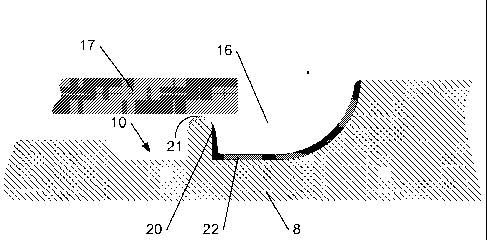
In a first step, illustrated in Figure 1, a layer of a first layer
forming material 14, which is hardenable and has the first colour, is
applied, as an in-mould coating, onto the first portion 11 of the mould
surface 10. This first portion 11 is situated on top of an upstanding ridge
15 of the mould surface 10. After having applied the first layer forming
material 14, a layer of a second layer forming material 16, which is
hardenable and has the second colour, different from the first colour, is
applied onto the second portion 12 of the mould surface and partially onto
the back of the first layer forming material 14 (see Figure 3). Before
applying the second layer forming material 16, the layer of the first layer
forming material 14, and preferably also the third portion 13 of the mould
surface, are preferably shielded off at least partially by means of a mask
17 (see Figure 2) so that the second layer forming material 16 can be
sprayed from a distance onto the mould surface. In a next step, the mask
17 is removed and a layer of a third layer forming material 18 is applied
onto the third portion 13 of the mould surface and at least partially onto
the back of the first layer forming material 14. In the embodiment
illustrated in Figure 4, the third layer forming material 18 is also applied
partially onto the back of the second layer forming material 16. The third
layer forming material 18 can thus be sprayed without having to use a
mask. After having applied the different layers of the layer forming
materials 14, 16 and 18, each of these layers is allowed to harden, either
before or after having applied a subsequent layer, to produce respectively
the layers 21, 22 and 23 forming the surface layer 1.
After having produced the surface layer 1, it can be
removed from the first mould section 8 and it can subsequently be
positioned in a separate backfoaming mould to produce the trim part 2 by
a so-called indirect backfoaming process. In Figures 5 and 6, a direct
backfoaming process is however illustrated wherein the surface layer 1 is
left onto the surface 10 of the first mould section 8 and wherein the rigid
CA 02608523 2007-11-14
WO 2006/122928 PCT/EP2006/062327
-11-
substrate 3 is positioned onto the second mould section 9. A foamable
composition 19 is then poured onto the back of the surface layer 1, the
mould is closed and the foamable composition 19 is allowed to foam to fill
the space between the surface layer 1 and the rigid substrate 3. After
curing of the foam, the mould can be opened and the trim part 2 can be
removed from the mould.
In the method illustrated in Figures 1 to 4, the second layer
forming material 16 was applied after having applied the first layer
forming material 14 and the third layer forming material 18 was applied
after having applied the second layer forming material 16. It is however
also possible to apply the third layer forming material 18 onto the mould
surface either before applying the second layer forming material 16 or
even before applying the first layer forming material 14 thereon. When
applying it before the second layer forming material 16, the third layer
forming material 18 is not only applied onto the third portion 13 of the
mould surface but also partially onto the back of the layer of the first layer
forming material 14. In this case, a mask can be used to shield the layer
of the first layer forming material 14, and preferably also the second
portion 12 of the mould surface, at least partially off when applying the
layer of the third layer forming material 18 whilst a mask is no longer
needed for applying the second layer forming material 16. When applying
the third layer forming material 18 onto the mould surface 10 before
applying the first layer forming material 14 thereon, the first portion 11 of
the mould surface is preferably at least partially shielded off by means of
a mask when applying the layer of the third layer forming material 18 onto
the mould surface. Depending on the width of the first portion 11 of the
mould surface also the second portion 12 of the mould surface is
preferably at least partially shielded off by means of that mask. Again, a
mask is no longer needed for applying the second layer forming material
CA 02608523 2007-11-14
WO 2006/122928 PCT/EP2006/062327
-12-
16 since this material may be sprayed also onto the back of the layer of
the third layer forming material 18.
An essential feature of the method according to the
invention is that the second layer forming material 16 is not only applied
onto the mould surface but also at least partially onto the back of the first
layer forming material 14 so that the layer of the first layer forming
material 14 has an edge 20 which is situated (on the mould surface)
underneath the layer of the second layer forming material 16 and which
forms, on the visible side (front side) of the finished surface layer, the
transition between the first and the second colour. According to the
invention, at least a portion of this visible edge 20 is formed without
intervention of a mask when applying the first layer forming material 14
onto the first portion 11 of the mould surface 10. The first layer forming
material 14 is more particularly applied in such a manner that this portion
of the visible edge 20 is visually sharp. The portion of the visible edge
which is visually sharp preferably has a length of at least 5 cm or, if the
edge is shorter than 5 cm, preferably the total edge should be visually
sharp. Notwithstanding the fact that the visually sharp portion of the edge
should be produced without a mask, another portion of the edge could be
produced by means of a mask or a mask can be used to cover the
second 12 and/or the third portion 13 of the mould surface 10 so that no
drops or dirt can arrive onto these portions of the mould surface. The
edge of this mask is then situated at some distance from the first portion
11 of the mould surface.
A visually sharp edge means that the edge is either sharp or
comprises a transition zone between the two colours which is however so
narrow that, when looking at it with the naked eye in normal daylight and
from a distance of 30 cm, the edge appears to be sharp. Figure 9
illustrates very schematically an edge 20 of a grey first layer 21 which is
situated in front of a white second layer 22 and which is not visually
CA 02608523 2007-11-14
WO 2006/122928 PCT/EP2006/062327
-13-
sharp. The edge 20 is obtained by spraying the first layer forming
material 14 onto the mould surface, the second portion of which is
shielded off by means of a mask maintained, as described in EP-B-
0 804 327, on a distance from the mould surface. In practice it was found
that, in the best cases, the colour transition zone has a width of at least
1100 - 1200 pm.
In the method according to the invention, the first layer
forming material 14 is however preferably applied in such a manner that
the edge 20 is produced without a mask and is visually sharp. Preferably,
the first layer forming material is applied in such a manner onto the mould
surface that there is either substantially no colour transition zone or that
the transition zone has a width smaller than or equal to 500 pm, more
preferably smaller than or equal to 300 pm and most preferably smaller
than or equal to 150 pm. The way wherein the width of the colour
transition zone, or the absence of such a colour transition zone, can be
determined is illustrated in Figure 9.
First a line Lo following the contour of the first surface
portion 5 should be drawn. If there is a colour transition zone between the
first 5 and the second surface portion 6, this contour line Lo should be
drawn substantially in the middle of the transition zone. In Figure 9, the
contour line Lo is a straight line but curved contour lines are of course
also possible. After having drawn the contour line Lo, lines L, - Ln are
drawn parallel to the contour line Lo and each time at a distance from this
contour line increasing with a step of 50 pm towards the second surface
portion 6. When less than 2% of the surface defined between a line Ln
and a further line Ln+, (drawn parallel to the line Ln at a distance of 50 pm)
has the colour of the first surface portion 5, the last line Ln forms the
boundary of the transition zone at the side of the second surface portion
6. In the direction of the first surface portion 5, the same is done, i.e.
lines
L', - L'm are drawn at a distance increasing with steps of 50 pm towards
CA 02608523 2007-11-14
WO 2006/122928 PCT/EP2006/062327
-14-
the first surface portion 5 until less than 2% of the surface defined
between the last line L'n, and a further line L'R,+, (drawn parallel to the
line
LR, at a distance of 50 pm) has the colour of the second surface portion 6.
In the embodiment illustrated in Figure 9, a total of 22 lines L, L' had to be
drawn so that the colour transition zone has a width of 1.1 mm. Such a
wide transition zone can clearly be seen with the naked eye so that the
edge is not visually sharp.
To achieve a visually sharp edge without the use of a mask,
the first layer forming material 14 can be applied in different ways onto
the mould surface, i.e. different applicator devices can be used. First of
all it can be laid onto the mould surface by different techniques such as
brushing, scraping, rolling, pouring (with a pouring nozzle drawn over the
mould surface), tampon printing, flexography, etc. The first layer forming
material 14 may also be applied from a relatively small distance onto the
mould surface, in particular from a distance smaller than 20 mm,
preferably smaller than 10 mm. This can be done by spraying the
material from such a small distance, and with such a pressure and flow
rate onto the mould surface, that a visually sharp edge is formed. The
first layer forming material can also be poured or otherwise dosed onto
the mould surface so that it flows out on the mould surface. A person
skilled in the art knows different ways wherein such a visually sharp edge
can be achieved without the use of a mask. The first layer forming
material can be applied for example by brushing, painting, rolling, writing
(with a pen-like instrument) or printing (for example by flexography or by
ink jet printing) or even by spraying or pouring if this is done from a
sufficiently small distance (and at a sufficiently low pressure or flow rate)
from the mould surface.
The first layer forming material 14 has preferably a relatively
low viscosity, in particular a viscosity lower than 1000 mPa.s, preferably
lower than 500 mPa.s(at 25 C).so that it can be applied easier onto the
CA 02608523 2007-11-14
WO 2006/122928 PCT/EP2006/062327
-15-
mould surface. As illustrated in the figures, the first layer forming material
14 is preferably a water or solvent based paint which is applied in a layer
having preferably an average thickness smaller than 300 pm, more
preferably smaller than 100 pm.
As described hereabove, different techniques or applicator
devices can be used to apply such a paint onto the mould surface. Figure
1 shows schematically a cross-sectional view of a possible nozzle 25 of a
paint applicator device while Figure 10 shows a perspective view of this
nozzle 25. The nozzle 25 comprises a nozzle tip 26 screwed onto a tube
27. The nozzle tip 26 has a central channel 28 through which the paint is
dispensed at a controlled flow rate. In the embodiment illustrated in
Figures 1 and 10, the nozzle tip 26 has a V-shaped groove 29. For
applying the paint onto the mould surface, the nozzle is positioned onto
the ridge 15 so that the top of the ridge extends into the groove 29, with a
free space remaining between the top of the ridge and the bottom of the
groove. The central channel 28 in the nozzle tip 26 ends in the bottom of
the groove 29 so that the paint flows into this free space and arrives on
top of the ridge 15. The nozzle is moved along the ridge to deposit a layer
of paint onto the top of the ridge. The amount of paint is controlled by
adjusting the velocity of the nozzle moving along the ridge and the flow
rate of the paint through the nozzle. The amount of paint is controlled
more particularly in such a manner that the paint flows out over the top of
the ridge but does not run off. In this way, a visually sharp edge is
obtained.
Instead of a V-shaped groove, other groove shapes can be
provided, depending amongst others on the shape of the top of the ridge.
The shape and the size of the groove can also be adapted to enable to
apply the paint not onto a ridge but onto a substantially flat mould
surface. As explained hereabove, a ridge is no longer necessary to
CA 02608523 2007-11-14
WO 2006/122928 PCT/EP2006/062327
-16-
provide a groove in the surface layer or trim part wherein the actual
colour transition is hidden from view.
The second layer forming material 16 can be a same
material as the first layer forming material 14 but having a different
colour. It can thus also be a water or solvent based paint which is applied
in a layer having preferably an average thickness smaller than 300 pm, in
particular smaller than 100 pm. In the trim part, this in-mould paint layer
can be given the required support by moulding a foam layer of a
sufficiently high density onto the back of the paint layer. However, in a
preferred embodiment, at least one elastomeric skin layer is applied onto
the back of the paint layer to form, together with the paint layer, the
surface layer. This elastomeric skin layer has in particular an average
thickness greater than 0.4 mm, preferably greater than 0.6 mm but
smaller than 8 mm, preferably smaller than 6 mm and more preferably
smaller than 4 mm (the average thickness is determined by dividing the
volume of the skin layer by its surface area).
Instead of applying first an in-mould coating layer, i.e. a
paint layer, it is also possible to apply directly, as illustrated in the
figures,
a curable skin material, in particular a curable polyurethane skin material,
forming after curing a non-cellular or micro-cellular elastomeric skin layer,
as second layer forming material 16 onto the mould surface 10. Since it is
not covered by a paint layer, this skin material should preferably be light-
stable. Suitable polyurethane formulations, which can be sprayed onto
the mould surface, are disclosed in EP-B-O 379 246. These formulations
can be sprayed for example by the techniques described in EP-B-
0 303 305 and in EP-B-0 389 014. On the other hand, it is also possible
to apply these formulations by pouring them on the mould surface. The
polyurethane formulations can also be moulded in accordance with a
reaction injection moulding process (RIM). Suitable RIM formulations are
disclosed in EP-B-0 929 586. They can be moulded for example by a RIM
CA 02608523 2007-11-14
WO 2006/122928 PCT/EP2006/062327
-17-
process as disclosed in WO 02/11974. The layer of the second layer
forming material is however preferably applied by spraying or pouring this
material, which is preferably a curable liquid, onto the mould surface.
The skin material which is either applied directly onto the
mould surface or onto an in-mould coating may also be a thermoplastic
material. The layer or this thermoplastic material can be applied by the
usual moulding methods such as the powder or liquid slush moulding
processes to produce flexible moulded sheets or panels of thermoplastic
materials such as PVC. In these methods, the thermoplastic material is at
least partially melted, in particular until at least a gel is obtained, and
allowed to harden so that it adheres to the previously applied layer(s).
For applying the third layer forming material 18, the same
materials and application techniques can be used as described here
above for the second layer forming material 16. The third layer forming
material 18 is preferably of the same nature as the second layer forming
material 16, for example a curable polyurethane composition, but they
may also be of a different nature. Moreover, both materials may be
applied by a different technique.
Especially when the third layer forming material has
substantially the same colour as the first layer forming material, the edge
of the layer of the third layer forming material does not have to be visually
sharp whilst the edge of the first layer forming material is preferably
visually sharp. In this case, the first layer forming material is preferably
applied by means of an applicator device which enables to achieve a
visually sharp edge without intervention of a mask whilst the third layer
forming material is preferably applied by means of another applicator
device, more particularly by means of an applicator device, in particular a
spray device, which enables to spread the third layer forming material
more easily over a larger surface area.
CA 02608523 2007-11-14
WO 2006/122928 PCT/EP2006/062327
-18-
The third layer forming material 18 can be applied before
the first layer forming material 14, after this first layer forming material
14
but before the second layer forming material 16, or after the second layer
forming material 16. In the preferred embodiment illustrated in the figures,
the third layer forming material 18 is a curable skin material which is not
only applied onto the third portion 13 of the mould surface but also on the
back of the layer of the first layer forming material 14 so that it provides a
support layer for this paint layer. More generally, it is preferable to apply
the first layer forming material first onto the mould surface, i.e. before the
second and any third layer forming material, since it is easier to apply this
first layer forming material by means of the techniques enabling to
achieve a visually sharp edge onto a mould surface which isn't covered
yet with any of the other materials.
If both the second and the third layer forming material are a
water or solvent based paint, and if a micro-cellular or non-cellular skin
layer is applied on both paint layers, the paint layers are preferably
applied first onto the mould surface so that the skin layer can be applied
in one step onto all of the paint layers (including the first layer forming
material which may also be a paint layer).
The surface layer formed by any paint and/or elastomeric
skin layers is preferably flexible or semi-flexible. It has in particular an
average thickness greater than 0.4 mm, preferably greater than 0.6 mm
but smaller than 8 mm, preferably smaller than 6 mm and more
preferably smaller than 4 mm.