Note: Descriptions are shown in the official language in which they were submitted.
CA 02608638 2007-11-15
W02007/054233 - 1 - PCT/EP2006/010506
Cylinder/piston unit having a non-cylindrical chamber
Description
The invention relates to a cylinder/piston unit with a
cylinder and with a piston guided therein, the cylinder
and the piston enclosing a chamber that can be filled
at least temporarily with active substance, and the
cylinder having at least one discharge element at its
front end.
An ampoule for a needleless injection device is known
from DE 201 05 183 U1. Located in the ampoule, inside a
cylindrical chamber, there is a medicament which, for
subcutaneous administration, is ejected as a jet of
liquid by means of a cylindrical piston. The piston of
the commercially available product is lubricated by
means of silicone gel in the cylindrical chamber. When
these ampoules are used in a conventional injection
device, the ejection pressure drops considerably over
the piston stroke. Moreover, the silicone-containing
lubricant for the piston is discharged with each dose
of medicament.
The object of the present invention is therefore to
develop a cylinder/piston unit which, while having a
small overall volume and requiring few component parts,
ensures simple and safe handling and, in the filled
state, is closed off in a manner impervious to gas and
moisture and can be stored over long periods.
This object is achieved by the features of the main
claim. The cross section of the chamber in the cylinder
or the cross section of the inner wall of the cylinder
increases at least in some areas from the front towards
the rear, the cylinder end with the discharge element
being at the front. The piston comprises, at least in
the front area, an elastic skirt whose front outer
edge, when the piston is unloaded, covers a cross-
CA 02608638 2007-11-15
W02007/054233 - 2 - PCT/EP2006/010506
sectional surface area that is greater than a surface
area covered by a contour line.
By means of the invention, a cylinder/piston unit is
created which can be used, for example, in a
subcutaneous injection device and in which, as a result
of the structural configuration of the inner wall of
the cylinder and of the outer contour of the piston,
the drop in pressure at the discharge element over the
piston stroke is much less than in known cylinder/
piston units that are operated in the same way.
Moreover, the cylinder/piston unit comprises a piston
which is self-sealing, in accordance with the technical
principle of self help, and which, by virtue of the
configuration of its sealing means, sits in the
cylinder free of lubricant.
Further details of the invention will become clear from
the dependent claims and from the following description
of illustrative embodiments depicted schematically in
the figures, where:
Figure 1 shows a cylinder/piston unit, with a piston
at two end positions;
Figure 2 shows a cylinder/piston unit with the end
faces closed off by films;
Figure 3 shows a plan view (enlarged by 50%) of the
front closure film coated with adhesive;
Figure 4 shows a cylinder/piston unit with the closure
film partially detached;
Figure 5 shows a cylinder/piston unit with several
nozzles;
Figure 6 shows a plan view (enlarged by 50%) of the
cylinder from Figure 5;
CA 02608638 2007-11-15
W02007/054233 - 3 - PCT/EP2006/010506
Figure 7 shows partial section through an emptied
cylinder/piston unit with piston, and without
separate sealing element;
Figure 8 shows cross sections of the unloaded piston;
Figure 9 is a diagram of pressure and piston stroke.
Figure 1 shows a cylinder/piston unit as is used, for
example, in a subcutaneous injection device. it
comprises a cylinder (10) and a piston (50), for
example without a piston rod. Both enclose, within a
chamber (30), a product (1) that is to be administered
subcutaneously or a liquid carrier material, for
example distilled water or physiological saline
solution (see Figures 2, 4 and 5) . For better clarity,
the piston (50) in Figure 1 is shown in a front
position (67) and in a rear position (69). The
cylinder/piston unit is, for example, designed to be
used once and then disposed of. It is used to
administer a volume of medicament of 0.1 to 2 ml, for
example. If appropriate, a volume of medicament of 3 ml
can also be administered. The cylinder (10), designed
here only by way of example without an integrated
injection needle, withstands a temporary pressure load
of at least 300 x 105 Pa during use in a subcutaneous
injection device.
The cylinder (10) has roughly the shape of the syringe
barrel of a standard disposable syringe. At the front
end (11), there is a nozzle-like discharge element (36)
which, in the front and, for example, flat end face
(12) of the cylinder, terminates in what is for example
a circular opening (41) of a free jet aperture (39). If
appropriate, instead of the nozzle-like discharge
element, an injection needle (not shown in the present
figures) can be fitted.
CA 02608638 2007-11-15
W02007/054233 - 4 - PCT/EP2006/010506
An adapter flange (21), a flange (27) with locking ribs
(see Figure 4), a threaded flange (23) (see Figure 5),
a bavonet-type flange or something comparable to these
is integrally formed on or secured on the rear end.
Here too, the rear end face (16) of the cylinder in the
area of the flange can be flat and perpendicular to the
centre line (9) of the cylinder.
Situated between the adapter (21, 23, 27) and the front
end face (12), there is an outer contour (20) with, for
example, a cylinder jacket shape or a frustoconical
shape. The shape of the outer contour (20) of the
cylinder (10) is in most cases independent of the
functional designation "cylinder (10)". The outer
contour (20) can, among other things, have one or more
partial flattened areas in order to avoid its
inadvertently rolling to the sides when handled on a
flat support surface.
The adapter flange (21) according to Figures 1 and 2 is
used, like the other adapter contours (23, 27), to fix
the cylinder in a dimensionally stable and partially
height-variable manner on the subcutaneous injection
device. Here, a collar of the injector housing or
another adapter contour engages round the corresponding
flange of the cylinder (10). An adapter can be
dispensed with in the case of an injector design having
an almost complete cylinder holder on the injector
housing.
The external diameter of the adapter flange is, for
example, greater by at least one cylinder wall
thickness than the external diameter of the adjacent
outer contour (20) of the cylinder (10) . The flange
thickness is of the order of the thickness of the
cylinder wall. The flange too can have one or more
flattened areas (19) about its sides in order to avoid
a rolling movement (see Figures 5 and 6). Instead of
CA 02608638 2007-11-15
w02007/054233 - 5 - PCT/EP2006/010506
the flattened areas (19), it is also conceivable to
provide notches, grooves, beads or flutings.
In Figure 2, a cylinder (10) is shown that has a flange
(27) with locking ribs. The locking ribs (28) form, in
cross section, a kind of sawtooth profile with five
teeth and four interstices between these. By means of
the rearwardly oriented 450 bevels (29) of the teeth,
the cylinder (10) can be inserted into the injector
housing in, for example, five different locking
positions. A corresponding housing mantle engages, for
example elastically, in the corresponding annular space
of the tooth interstices.
The thread (25) of the threaded flange (23) according
to Figures 5 and 6, covers, relative to the
circumference, ca. 60% of the flange contour in two
threaded portions (24), for example lying opposite one
another.
In the illustrative embodiments shown, the flange (27)
with locking ribs and the threaded flange (23) extend
along the rear 50% of the length of the cylinder.
In the case of a cylinder with only one discharge
element (36), the inner contour of the cylinder (10)
comprises the cylinder inner wall (31), if appropriate
with a bevel (42), a cylinder base (32), a discharge
funnel (35), a nozzle bore (36), and a free-jet
aperture (39).
According to the illustrative embodiments shown, the
cylinder inner wall (31), which is smooth for example,
tapers linearly from the rear forwards. According to
Figures 1, 2, 4 and 5, it also extends over the entire
piston stroke area (4). All cross sections of the inner
wall (31) of the cylinder outside the area of the
discharge funnel or funnels (36) are also circular. For
example, the cylinder inner wall (31) only narrows over
CA 02608638 2007-11-15
W02007/054233 - 6 - PCT/EP2006/010506
a piston stroke (3) of 18 millimetres from a diameter
of 7 millimetres to 6 millimetres. This corresponds to
a taper angle of about 3.2 degrees.
Instead of the specific cases shown here, the cross
sections can also change their shape, in addition to
their surface area, over the piston stroke (3). Thus,
the cylinder inner wall could for example have an oval
cross-sectional shape at its rear end, while a cross
section lying near the front end has a round or
polygonal shape. Moreover, it is also possible for the
change in cross-sectional shape along the piston stroke
to be non-linear. For example, in order to reduce the
piston braking action, the taper can start only in the
final third of the ejection stroke. The transition
between portions having different cross sections is
generally constant.
Between the inner wall (31) of the cylinder and the
rear end face (16), a 15 bevel (42) can be provided in
order to make fitting of the piston (10) easier.
The cross-sectional taper can, if appropriate, also
relate only to the chamber (30). In this case, the
piston (50) arranged in a rear position (69) is
situated along its entire length in a wall portion
with, for example, a cylindrical contour.
The discharge funnel (35) tapers between the cylinder
base (32) and the nozzle bore (36) in a non-linear
manner, in order to permit better flow guidance. A
constant transition.. between the discharge funnel (35)
and the nozzle bore (36) is sought. The nozzle bore
(36), whose diameter lies for example between 0.1 and
0.2 millimetres, is two to four times as long as its
diameter. The nozzle bore (36) is adjoined by a free-
jet aperture (39) in the shape of a cylinder chamber.
The aperture (39) has a flat base, which is
additionally oriented perpendicular to the centre line
CA 02608638 2007-11-15
w02007/054233 - 7 - PCT/EP2006/010506
of the nozzle bore (36) . Its diameter corresponds to
eight to siXteen times the nozzle bore diameter, if the
aperture depth is at least twice as great as the nozzle
bore length.
Figures 5 and 6 show, inter alia, a cylinder (10) with
three discharge elements in the form of nozzle bores
(36). The nozzle bores (36) have centre lines (37) that
are parallel to the centre line (9). They are arranged
in an equidistant formation on a hole circle (38) . The
latter is only slightly smaller than the minimum
chamber diameter in the piston stroke area (4). Oblique
funnels extend between the respective nozzle bore (36)
and the cylinder base (32). The cylinder base (32)
bulges inwards between the funnels.
The material used for the cylinder (10) is a
transparent, amorphous thermoplastic, for example a
copolymer or copolymers based on cycloolefins and
ethylenes or a-olefins (COC).
The piston (50) guided in the cylinder (10) must
compensate for the change in cross section of the
cylinder inner wall by having a corresponding reduction
in its sealing cross section. The wall friction should
be allowed to increase only to an inappreciable extent.
To achieve this inter alia, the piston (50) is
divisible into three portions (51, 61, 71) and has, in
a front portion (51) and rear portion (71), in each
case a skirt (52, 72), see Figure 8. The central piston
portion (61) is located between the portions (51) and
(71).
The central portion (61) has the shape of a truncated
cone. It fits into the front end of the chamber (30) in
a manner free from deformation. At the front, it is
adjoined centrally by a front core (59). The front
skirt (52) is situated around the core (59) . According
CA 02608638 2007-11-15
W02007/054233 - 8 - PCT/EP2006/010506
to Figure 8, an axial annular groove (57) lies between
the skirt (52) and the core (59) . The rear skirt (72)
and the rear core (79) also have a comparable
structure. The skirts (52, 72), the cores (59, 79) and
the central portion (61) each have a rotationally
symmetrical basic shape. All the parts and structural
components mentioned have congruent centre lines. The
individual core (59, 79) protrudes past the respective
skirt (52, 72) by a few tenths of a millimetre, for
example.
According to Figures 8, 1, 2 and 4, the front core (59)
has a straight, positive cone envelope as its end face.
According to Figures 5 and 7, the cone envelope of the
front end face is negative, that is to say shaped
inward towards the centre of gravity of the piston.
Almost any other rotationally symmetrical end face is
conceivable, as long as it ensures that, with the
piston (50) lying in the front position (67), it leaves
the least possible residual volume (6) relative to the
cylinder base (32) lying at least partially on it.
The front skirt (52), which extends along a quarter to
a third of the piston length, is a thin-walled ring
that opens in a funnel shape in the unloaded state. The
front outer edge (53) of the skirt (52) encloses a
cross-sectional surface area (55) which, according to
Figure 8, is greater than a cross-sectional surface
area (63) whose circumfere-1.ce is defined by an
imaginary contour line (62), lying at the foot of the
skirt (52). The contour line (62) is indicated by
broken lines in a partial.view of the piston (10) in
Figure 4.
During a working stroke, the contour line (62) does not
change its length or only barely changes its length,
i.e. the cross section (63) enclosed by it remains
essentially constant. By contrast, with linear tapering
of the inner wall (31) of the cylinder, the front outer
CA 02608638 2007-11-15
W02007/054233 - 9 - PCT/EP2006/010506
edge (53) shortens over the entire working stroke. In
the front piston stroke area (4) (see Figure 1), the
front outer edge (53) is even shorter than the contour
line (62) in the area of the sealing element (58).
According to Figures 1, 2, 4, 5 and 8, the sealing
element (58) is located in the axial annular groove
(57). The sealing element (58) is a separate sealing
ring or an inserted permanently elastic sealing
compound. When the piston (50) has arrived in the front
position (67), said sealing element (58) connects the
front inner edge (54) of the skirt (52) flush with the
front end face towards the core. This contributes to
minimizing the residual volume (6) in the chamber (30).
The sealing element (58) can also extend inside the
skirt (52), that is to say can completely replace the
front core (59) . In both cases, the sealing element
(58) bears sealingly on the inner wall (56) of the
skirt. The pressure forces that arise during the
working stroke act indirectly on the inner wall (56) of
the skirt via the sealing element (58).
Moreover, it is possible to dispense with the sealing
element (58) (see Figure 7) . There, the front skirt
(52) protrudes into a corresponding annular groove
(33).
According to Figure 8, a magnetic or magnetizable metal
plate (77) is arranged in the rear core (79) of the
piston (50) . It covers, for example, 50% of the rear
cross-sectional surface area and is 0.5 to 1 millimetre
thick. The metal plate (77) facilitates the handling of
the piston (50) upon automatic assembly of the
cylinder/piston unit. By means of the magnetic force
and/or gravitational force of the metal plate (77), the
piston (50) can be oriented and received in a targeted
manner.
CA 02608638 2007-11-15
W02007/054233 - 10 - PCT/EP2006/010506
A tetrafluoroethylene/hexafluoropropylene copolymer
(FEP) is used as the material for the piston (50). This
material has self-lubricating properties in conjunction
with the aforementioned material of the cylinder (10),
so that no separate lubricating agents are needed
between piston (50) and cylinder (10). Alternative
materials that can be chosen are, among others,
perfluoroalkoxy copolymer (PFA), tetrafluoroethylene
(TFE) or polyvinylidene fluoride (PVDF).
If appropriate, it is also possible to use a
combination of materials in which the core area (59,
61, 79) of the piston (50) is made from a material of
low elasticity, while the skirts (52, 72) are made from
a highly elastic material.
According to Figure 1, the piston (50), in its rear
position (69), bears resiliently on the inner wall (31)
of the cylinder via the skirts (52, 72). Since the
internal diameter is relatively large in this area of
the cylinder, a gas-filled or air-filled gas cushion
(7) forms between the radial outer wall of the piston
and the inner wall (31) of the cylinder. If the piston
(50) is now actuated by a corresponding drive mechanism
of the subcutaneous injector, the cylinder's inner wall
(31) narrows over the stroke and causes the compacting
gas cushion (7) to be displaced counter to the
direction of movement of the piston. The gas escapes at
overpressure continuously from between the rear outer
edge (73) of the skirt (72) and the inner wall (31) of
the cylinder. In doing so, the rear skirt (72) lifts
from the inner wall of the cylinder by an amount in the
m range. With the lubrication provided by the gas, the
advancing skirt (72) slides almost free from friction
along the inner wall (31) of the cylinder. Only in the
lower position (67) of the piston is the gas cushion
(7) almost completely displaced. By contrast, the front
skirt (52) bears with a sealing action, at least via
CA 02608638 2007-11-15
W02007/054233 - 11 - PCT/EP2006/010506
the front outer edge (53), permanently on the inner
wall (31) of the cylinder.
During the working stroke of the piston (50), the
liquid (1) with which the cylinder is filled is
discharged through the nozzle bore (36) in a hard jet
of liquid. If, for example, a mechanical, pneumatic or
comparable kind of spring, or a system of springs, is
used for the drive mechanism, then the drive force
generally subsides continuously over the piston stroke.
Consequently, the pressure of the jet of liquid also
subsides accordingly. As a result of the narrowing of
the cross section of the inner wall of the cylinder
over the piston stroke (3), the effective piston
surface becomes increasingly smaller. By this means,
the pressure of the jet of liquid reduces considerably
less than in the case of a cylinder with a cylindrical
inner wall (see Figure 9).
In Figure 9, these relationships are depicted in a
diagram of pressure over travel. The pressure (p) is
plotted in pascals on the abscissa. The piston stroke
(s) is plotted in millimetres on the ordinates. The
curve (1.) shows the pressure profile in a conical
chamber (30) according to Figure 1, while the curve
(2.) shows the pressure profile for a cylindrical
chamber. The curve (1.) is flatter than the curve (2.).
This means that a higher pressure is available to the
jet of liquid shortly after the start of the jet and
until the content (1) has been used up, and the
difference in the pressures, dependent on travel,
increases permanently as the piston stroke increases.
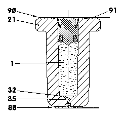
In a cylinder/piston unit, the two end faces (12, 16)
of the cylinder (10) can have openings (41, 45) closed
off by closure means (80, 90) that are impervious to
gas and moisture. These closure means (80, 90) are
films (81, 91) and/or coatings (92).
CA 02608638 2007-11-15
W02007/054233 - 12 - PCT/EP2006/010506
Filled cylinder/piston units are shown in Figures 2, 4
and 5. According to Figure 2, the rear end face (16) of
the cylinder (10) is closed by a closure means (90)
consisting of a detachable sealing film (91) that is
impervious to gas and liquid. The siliconized sealing
film (91) is, for example, a PET film, an HTPE film, a
PE film or a BOPP film that is bonded or sealed onto
the end face (16) of the cylinder.
In Figures 4 and 5, a spray-on coating (92) is used
instead of a sealing film (91). The sprayed-on lacquer
(92) is based on a cellulose derivative. It can also be
made from a comparable and biocompatible material. The
sprayed-on lacquer (92) is applied sealingly to the
rear end face (16), to part of the cylinder inner wall
(31) and to the rear end face of the piston (50). When
using the cylinder/piston unit sealed in this way, the
lacquer (92) does not have to be removed before
insertion into the injector. It is simply torn open by
the injector ram driven by the piston (50) (see Figure
7). In the latter figure, a residue of the lacquer (92)
can.be seen adhering to the piston (50).
The opening/openings (41) on the front end face (12) of
the cylinder is/are closed off by a detachable sealing
film (81) that comprises at least two different
adhesive regions, the first adhesive region, arranged
around the opening/openings (41), consisting of a
contact adhesive (83) which has a greater affinity to
the end face (12) of the cylinder than to the sealing
film (81), while the second adhesive region, covering
the opening/openings (41), contains a closure adhesive
(84) that has a greater affinity to the sealing film
(81) than to the material of the cylinder.
CA 02608638 2007-11-15
W02007/054233 - 13 - PCT/EP2006/010506
List of reference numbers:
1 active substance, filling
3 piston stroke
4 piston stroke area
5 half taper angle
6 residual volume
7 gas cushion
9 centre line
10 cylinder
11 front end, end with discharge element
12 end face, front
15 rear end
16 end face, rear
19 flattened area
outer contour
20 21 adapter flange
23 threaded flange
24 threaded portions
thread
27 flange with locking ribs
25 28 locking ribs
29 bevels
chamber
31 cylinder inner wall, inner contour
30 32 cylinder base
33 annular groove
outflow funnel
36 nozzle bore, discharge element
35 37 centre lines of nozzle bores
38 hole circle, cylinder on which centre lines (37)
lie
39 free jet aperture
CA 02608638 2007-11-15
W02007/054233 - 14 - PCT/EP2006/010506
41 opening, front
42 chamber bevel, rear
45 opening, rear
50 piston
51 piston portion, front
52 skirt, front, elastic
53 skirt outer edge, front
54 skirt inner edge, front
55 cross section to outer edge
56 skirt inner wall
57 axial annular groove
58 piston seal, sealing ring, sealing compound
59 piston core, front
61 piston portion, central, frustoconical
62 contour line, imaginary
63 cross section to contour line (62)
67 piston position, front, forward end position
68 piston position, centre
69 piston position, rear
71 piston portion, rear
72 skirt, rear, elastic
73 outer edge, rear
77 plate, magnetizable
79 piston core, rear
80 front closure means
81 sealing film, detachable
82 tear-off tab
83 contact adhesive
84 closure with silicone adhesive
90 rear closure means
91 sealing film
92 coating