Note: Descriptions are shown in the official language in which they were submitted.
CA 02608901 2007-10-29
1
BOLT OR NUT TIGHTENING DEVICE
FIELD OF THE INVENTION
The present invention relates to bolt or nut tightening
devices comprising the combination of a tightening assisting
unit and input means coupled to the unit, the tightening
assisting unit comprising a bolt or nut engaging portion, a
reaction receiver and a tightening torque measuring unit.
BACKGROUND ART
The present applicant has previously proposed a bolt or
nut tightening device which comprises a tightening torque
measuring unit connected to the output shaft of a power
tightening machine, and a socket having a reaction receiver
and connected to the output shaft of the measuring unit
(JP2006-21272A).
With proposed bolt or nut tightening device, the power
tightening machine serving as input means can be an existing
one, and the tightening torque measuring unit is adapted to
indicate actual values of tightening torque.
The tightening torque measuring unit comprises a strain
gauge provided on a tubular body connected to an outer output
shaft of the power tightening machine coaxially therewith.
The tubular body is externally provided with a circuit board
for converting the amount of strain of the strain gauge to a
corresponding amount of tightening torque, an indicator for
indicating the amount of tightening torque and a battery. The
circuit board, the indicator and battery are covered with a
tubular casing coaxial with the tubular body.
To accommodate the circuit board, the indicator and the
CA 02608901 2007-10-29
2
battery in an annular space inside the tubular casing around
the tubular body, the casing needs to have a length and an inside
diameter fully sufficient to position these components to be
covered within the casing.
The tubular casing serves to protect the components of
the tightening torque measuring unit and must have high
rigidity for use in work environments such as work sites wherein
the device is likely to collide with workpieces or to slip off
from the hand to fall.
This gives the tightening torque measuring unit an
increased outside diameter, a larger length and greater
weight.
The tightening torque measuring unit itself has no
reduction mechanism incorporated therein, so that large bolts
or nuts to be tightened by controlling the tightening torque
require an expensive power tightening machine of large size
serving as input means and having a reduction mechanism for
effecting a great reduction.
If a great tight torque measuring unit is connected to
the power tightening machine of large size, the machine is not
fully satisfactory in maneuverability and ease of use.
The torque indicator of the tightening torque measuring
unit is adapted to indicate the digits of a numerical value
as arranged axially of the tubular casing and therefore has
the problem that it is difficult for the worker to read the
values while operating the power tightening machine.
An object of the present invention is to provide a bolt
or nut tightening device wherein use can be made of an existing
inexpensive small power tightening machine or a manual wrench
CA 02608901 2007-10-29
3
as input means and which can be prevented from becoming greater
in outside diameter and length although including a planetary
gear mechanism, the device being highly maneuverable and easy
to use and having a tightening torque indicator which is easy
to watch.
SUMMARY OF THE INVENTION
The present invention provides a bolt or nut tightening
device which comprises the combination of a tightening
assisting unit having an outer shaft and an inner shaft
coupled to a planetary gear mechanism coaxially therewith and
rotatable in directions opposite to each other, the outer shaft
having a reaction receiver projecting therefrom sideways, the
inner shaft being provided with an engaging portion engageable
with a bolt or nut to be tightened, and input means coupled
to the planetary gear mechanism. The outer shaft is provided
with a tightening torque measuring unit, which comprises a
strain gauge or like strain sensor provided on the outer shaft,
a circuit board for converting the amount of strain of the
outer shaft as detected by the strain sensor to an amount of
tightening torque, an indicator for indicating the amount of
tightening torque, a battery, and a case for accommodating the
circuit board, the indicator and the battery, the case being
attached to the outer shaft and projecting toward the same
direction as the reaction receiver, the case being so sized
as to be hidden by a contour of the reaction receiver and being
so positioned as to be hidden behind the reaction receiver
when seen from the forward end side of the engaging portion
In the bolt or nut tightening device of the invention,
the indicator is adapted to indicate digits of a numerical value
CA 02608901 2007-10-29
4
as arranged preferably in the direction of projection of the
case.
In the bolt or nut tightening device of the invention,
the case is rotatable preferably about a rod orthogonal to an
axis of the outer shaft.
According to an embodiment of bolt or nut tightening
device of the invention, the input means is a power tightening
machine having the two output shafts of an inner output shaft
and an outer output shaft coaxial therewith, and an input
receiver provided in the tightening assisting unit has a first
connecting member for detachably connecting the outer shaft
of the tightening assisting unit to the outer output shaft of
the power tightening machine so as to be rotatable therewith,
and a second connecting member for detachably connecting an
input shaft of a system for rotatingly driving the engaging
portion of the tightening assisting unit to the inner output
shaft (98) of the power tightening machine so as to be
rotatable therewith.
According to another embodiment of bolt or nut tightening
device of the invention, the input means is a power tightening
machine having a single output shaft, and an input receiver
provided in the tightening assisting unit has a connecting
member for detachably connecting an input shaft of a system
for rotatingly driving the engaging portion of the tightening
assisting unit to the output shaft of the power tightening
machine so as to be rotatable therewith.
According to another embodiment of bolt or nut tightening
device of the invention, the input means is a manual wrench,
and an input receiver provided in the tightening assisting unit
CA 02608901 2007-10-29
has a connecting member for detachably connecting an input
shaft of a system for rotatingly driving the engaging portion
of the tightening assisting unit to an output shaft of the
manual wrench so as to be rotatable therewith.
5 According to another embodiment of bolt or nut tightening
device of the invention, the input means is a manual wrench,
and an input receiver provided in the tightening assisting unit
comprises a connecting member for detachably connecting an
input shaft of a system for rotatingly driving the engaging
portion of the tightening assisting unit to an output shaft
of the manual wrench so as to be rotatable therewith and a
one-way clutch attached to the tightening assisting unit for
permitting the manual wrench to rotate in a desired direction
but preventing the manual wrench from rotating in a direction
opposite to the direction.
BRIEF DESCRIPTION OF THE DRAWINGS
FIG. 1 is a sectional view of a tightening device of a
first embodiment:
FIG. 2 is a sectional view of an input receiver of the
tightening device and input means thereof as separated from
the receiver;
FIG. 3 is an exploded perspective view of a tightening
assisting unit:
FIG. 4 is a view in section taken along the line A-A in
FIG. 1;
FIG. 5 is a view in section taken along the line B-B in
FIG. 1;
FIG. 6 is a sectional view of a tightening device of a
second embodiment;
CA 02608901 2007-10-29
6
FIG. 7 is a sectional view of an input receiver of the
tightening device and input means thereof as separated from
the receiver;
FIG. 8 is a sectional view of a tightening device of a
third embodiment ; and
FIG. 9 is a sectional view of an input receiver of the
tightening device and input means thereof as separated from
the receiver.
DETAILED DESCRIPTION OF THE INVENTION
The present invention will be described in detail with
reference to the embodiments shown in the drawings.
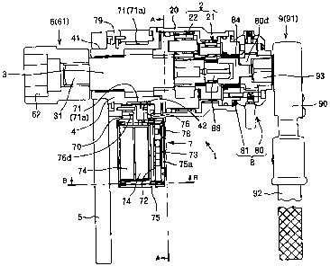
[First Embodiment (FIGS. 1 to 4)]
The illustrated bolt or nut tightening device comprises
a tightening assisting unit 1 having an engaging portion 6
engageable with a bolt or nut, and input means 9 coupled to
the unit 1.
The tightening assisting unit 1 comprises a planetary
gear reduction assembly 2 provided inside a tubular casing 20
and having two output shafts and one input shaft, an outer shaft
4 and an inner shaft 3 which are coupled to the assembly 2 and
projecting coaxially forward from the casing 20, the
above-mentioned engaging portion 6 projecting from the outer
end of the inner shaft 3 and engageable with the bolt or nut
(hereinafter referred to representatively as the "nut") to be
tightened, an input receiver 8 for detachably coupling the
input means 9 to the planetary gear reduction assembly 2, a
tightening torque measuring unit 7 mounted on the outer shaft
4 for indicating tightening torque, and a reaction receiver
5 attached to the outer shaft 4.
CA 02608901 2007-10-29
7
With reference to FIG. 2, the planetary gear reduction
assembly 2 comprises the combination of a first planetary gear
mechanism 21 on an input side and a second planetary gear
mechanism 22 on an output side.
The first planetary gear mechanism 21 comprises a first
sun gear 21a, a first planetary gear 21c, a first inner gear
21b provided on the inner side of the casing 20 and a first
planetary gear support frame 21d for rotatably supporting the
first planetary gear 21c.
The second planetary gear mechanism 22 comprises a second
sun gear 22a, a second planetary gear 22c, a second inner gear
22b provided on the inner side of the casing 20 and a second
planetary gear support frame 22d for rotatably supporting the
second planetary gear 22c.
The first and second sun gears 21a, 22a and the inner
shaft 3 are positioned coaxially, the first planetary gear
support frame 21d is in mesh with the second sun gear 22a, and
the second planetary gear support frame 22d is in mesh with
the inner shaft 3.
The first sun gear 21a is provided on its axis with an
inward square shaft 21a', which serves as an input shaft 88
connectable to the input means 9.
When the input shaft 88 rotates clockwise (the direction
in which right hand-threaded nuts are tightened), the inner
shaft 3, i.e., the nut engaging portion 6, also rotates
clockwise.
As shown in FIG. 1, the inner shaft 3 is provided at its
forward end with a square shaft 31, and the engaging portion
6 is removably attached to the square shaft 31. The engaging
CA 02608901 2007-10-29
8
portion 6 is a socket 61 having an engaging cavity 62 for the
nut to be tightened to fit in.
With reference to FIGS. 2 and 3, the outer shaft 4 is
in the form of a tubular body rotatably fitting around the inner
shaft 3 and is provided with a peripheral wall 43 at one end
of the casing 20. The peripheral wall 43 has a plurality of
cutouts 44 formed in the outer periphery thereof and
equidistantly arranged circumferentially thereof. A
plurality of projections 23 extending from the end face of the
casing 20 are engaged in the respective cutouts 44, whereby
the casing 20 is joined to the outer shaft 4 so as to be rotatable
therewith.
The outer shaft 4 has a furrow 42 formed in its outer
surface circumferentially thereof at an intermediate portion
of its length and is provided with an angular shaft portion
41 at its forward end.
The reaction receiver 5 is made from a thick metal plate
having great rigidity, by cutting the plate into a piece having
a length of about 25 cm. The reaction receiver 5 gradually
decreases in width as its extends from a base end toward an
outer end, and has a width of about 9 cm at its base end and
a width of about 5 cm at its outer end. The receiver 5 has
opposite circular-arc ends.
An angular hole 51 is formed in the base end portion of
the reaction receiver 5, and the angular shaft portion 41 of
the outer shaft 4 is tightly fitted in the hole 51. Accordingly,
the reaction receiver 5 is positioned orthogonal to the axes
of the inner and outer shafts 3, 4.
The tightening torque measuring unit 7 comprises a strain
CA 02608901 2007-10-29
9
sensor 71a for detecting the strain of the outer shaft 4 while
the nut is tightened, a circuit board 72 for converting the
amount of strain of the sensor 71a to an amount of tightening
torque, an indicator 73 for showing the amount of tightening
torque, batteries 74, a case 75 for accommodating these
components other than the strain sensor 71a, and a mount tubular
member 70 attached to and fitted around the outer shaft 4 for
supporting the case 75.
The mount tubular member 70 is fitted around the outer
shaft 4 to cover the furrow 42 therein and is held between the
peripheral wall 43 of the outer shaft 4 and a retaining ring
79 mounted on the shaft 4 and positioned toward the engaging
portion 6 so as to be rotatable with the outer shaft 4.
The mount tubular member 70 has a seat 70a protruding
toward the direction in which the reaction receiver 5 extends.
The case 75 is rotatably mounted on the seat 70a.
A case mount bore 70b is formed in the seat 70a in a
direction orthogonal to the inner and outer shafts 3, 4.
The case 75 projects in the same direction as the reaction
receiver 5.
The case 75 is in the form of a rectangular parallelepiped
which is so sized as to be hidden by the contour of the reaction
receiver 5, and is positioned as hidden behind the receiver
5 when seen from the front side of the engaging portion 6.
The case 75 has in the front wall thereof a front window
75a through which the indicator 73 can be seen, and an electric
switch 78 is provided at one side of the window 75a.
The case 75 has a tubular rod 76 projecting from the
center of one end thereof and rotatably fitting into the case
CA 02608901 2007-10-29
mount bore 70b. The rod 76 has a circumferential groove 76a
and cavities 76c arranged at equal intervals circumferentially
thereof.
A pin 76b provided on the retaining ring 79 fits in the
5 circumferential groove 76a for preventing the rod 76 from
slipping off, i.e., preventing the case 75 from slipping off
from the mount tubular member 70.
A click ball 76d provided on the retaining ring 79 and
biased by a spring fits in the cavity 76c to softly engaging
10 the rod 76.
According to the present embodiment, the case 75, as
positioned with its window 75a facing toward a direction
opposite to the reaction receiver 5, is rotatable through 180
deg about this position around half of the circumference of
the rod 76.
The cavities 76c in the rod 56 are arranged at five
locations at intervals of 45 deg about the axis of the rod so
as to render the case 75 rotatable through 45 deg at a time.
The case 75 as rotatably supported by the rod 76 on the
seat 70a is positioned in the closest proximity to the reaction
receiver 5.
As shown in FIG. 3, the strain sensors 71a of the present
embodiment are strain gauges 71 affixed to the furrowed portion
42 of the outer shaft 4. The strain gauge 71 is in an X shape
and affixed to each of four locations on the outer shaft 4 which
are equidistantly spaced apart circumferentially thereof.
The strain gauges 71 are electrically connected to the
circuit board 72 inside the case 75 by conductive wires (not
shown) extending through the tubular rod 76.
CA 02608901 2007-10-29
11
The circuit board 72 is positioned at the side of the
window 75a of the case 75, and the indicator 73 is disposed
between the window 75a and the circuit board 72.
The strain gauges 71 at the four locations on the outer
shaft 4 provide a bridge circuit (not shown) on the circuit
board 72. The indicator 73 shows a tightening torque value
corresponding to the average of amounts of strain at the four
locations on the outer shaft 4 where the strain gauges 71 are
affixed.
The indicator 73 of the present embodiment provides a
four-digit LED display. The display comprises the digits of
a numerical value as arranged in the length of the case 75.
The batteries 74 are placed in the case 75 between the rear
wall thereof and the circuit board 72.
When the switch 78 on the front wall of the case 75 is
pushed, the circuit board 72 is energized. If the circuit
board 72 remains inoperative for a predetermined period of time,
the circuit board 72 is automatically deenergized to prevent
useless consumption of the battery power.
The input means 9 is a manual wrench 91, which has a handle
92 and an output shaft 93 in the form of a square shaft and
provided at the head 90 of the handle 92 orthogonal to the
handle 92.
By virtue of a ratchet mechanism (not shown) incorporated
in the head 90, the output shaft 93 transmits the rotation in
one direction of the handle but idly rotates in the opposite
direction.
The input means 9 is detachably connected to the
tightening assisting unit 1 by an input receiver 8 of the unit.
CA 02608901 2007-10-29
12
The input receiver 8 comprises a lid assembly 81 for closing
an input-side opening of the casing 20, and a one-way clutch
80 as seen in FIG. 1.
The lid assembly 81 comprises a lid body 82, and a
coupling 84 rotatably provided in the center of the lid body
82 with a bearing sleeve 83 interposed therebetween.
The lid body 82 is provided on its outer periphery with
projections 82a equidistantly arranged circumferentially
thereof and fitted in respective cutouts 20a formed in an end
face of the casing 20, whereby the lid body 82 is attached to
the casing 20.
The coupling 84 has a square bore 84a formed in one side
thereof opposed to the input shaft 88, in the form of a square
rod, of the tightening assisting unit 1 for the input shaft
88 to fit in. The coupling 84 has a square shaft 84b projecting
from the other side thereof opposite to the bore 84a.
The one-way clutch 80 is fixed to the lid assembly 81
with a bolt 80c and has on its axis a socket member 80d which
is allowed to rotate only in one direction by a ratchet
mechanism 80e. The direction of rotation of the socket member
80d allowed by the ratchet mechanism 80e can be changed over
by manipulating a change lever 80a.
Formed in the socket member 80d in alignment with its
axis are a square hole 80f for the square shaft 84b of the lid
assembly 81 to fit in, and a square hole 80b for the output
shaft 93 of the manual wrench 91 to engage in.
The socket member 80d and the coupling 84 provide a
connecting member 87 for detachably connecting the input shaft
88 of the system for rotatingly driving the engaging portion
CA 02608901 2007-10-29
13
6 of the tightening assisting unit 1 to the output shaft 93
of the manual wrench so as to be rotatable therewith.
As shown in FIG. 1, the output shaft 93 of the manual
wrench 91 is coupled to the input shaft 88 of the planetary
gear reduction assembly 2 by the socket member 80d of the
one-way clutch 80 and the coupling 84 of the lid assembly 81
to provide a tightening device.
The circuit board 72 is energized by pushing the switch
78 of the tightening torque measuring unit 7.
With a nut engaged in the socket 61, the reaction receiver
5 is caused to bear on a projecting article in the vicinity
of the nut.
The manual wrench 91 is rotated in the nut tightening
direction, and then rotated reversely. When repeated, this
reciprocating movement rotates the output shaft 93 of the
manual wrench 91 only in the nut tightening direction by virtue
of the ratchet mechanism of its own and the one-way clutch 80,
rotating the input shaft of the tightening assisting unit 1
in the same direction. The rotation of the input shaft 88 is
subjected to speed reduction and power increase by the
planetary gear assembly 2 to rotate the socket 61 and tighten
up the nut.
The reaction of tightening is received at this time by
the projecting article in the vicinity of the nut through the
reaction receiver 5, so that the casing 20 of the gear assembly
2 and the output shaft 4 remain unrotated.
The amount of strain of the outer shaft 4 is detected
by the strain gauges 71 at the four locations on the outer shaft
4 which are equidistantly spaced apart circumferentially
CA 02608901 2007-10-29
14
thereof, and the average stain value is indicated as tightening
torque by the indicator 5.
Among the components of the tightening torque measuring
unit 7, the bulky components, i.e., the circuit board 72,
indicator 73 and batteries 74, are accommodated in the case
75, which is caused to project from the outer shaft 4 in the
same direction as the reaction receiver 5. Although the device
becomes locally projected outward greatly due to the presence
of the case 75, the present device need not use a large tubular
casing of increased rigidity as a shell for protecting the
components unlike the tightening torque measuring unit of the
aforementioned patent publication. The measuring unit 7 is
therefore small-sized and made lightweight in its entirety.
Since the case 75 projects from the outer shaft 4 sideways,
the case 75 appears susceptible to the impact to be involved
when the case strikes against the projecting article for the
reaction receiver 5 to bear on, workpiece or others. However,
the case 75 is so sized and positioned as to be hidden behind
the reaction receiver 5 having great rigidity and to be
subjected to the tightening reaction. The workpiece or the
like is therefore prevented from striking directly against the
case to obviate the likelihood of the measuring unit 7 becoming
broken.
Further when the tightening assisting unit 1 is placed
on the floor, the reaction receiver 5 will come into contact
with the floor to hold the case raised from the floor. This
eliminates the likelihood that the load of the tightening
assisting unit 1 will act on the case 75. In this respect,
the case 75 will be protected also by the reaction receiver
CA 02608901 2007-10-29
5.
Due to the tightening reaction to be exerted by the
projecting article in the vicinity of the nut through the
reaction receiver 5, the f our strain gauges 7 1 become different
5 in the amount of strain although slightly. The amount of
strain is measured by the strain gauges 71 arranged at the four
locations as described above, and the average value of measured
strain is indicated. This assures measurement with improved
reliability.
10 On the case 75 projecting from the outer shaft 4 in a
direction orthogonal to the axis thereof, the indicator 73
shows the digits of a numerical value as arranged along the
direction of projection of the case, so that indicator 73 can
be easily read by the worker using the manual wrench.
15 Because the case 75 is rotatable about the rod 76
orthogonal to the axis of the outer shaft 4, the indicator can
be positioned at an altered angle ensuring ease of reading.
Even if torsion acts on the tightening assisting unit
1 when the nut is tightened, elastically deforming the unit
1 in its entirety in the direction of torsion, the handle 92
will not rotate in a direction opposite to the tightening
direction in corresponding relation with the resulting elastic
restoration, since the one-way clutch 80 is provided in the
input receiver 8.
If the disadvantage of permitting slight reverse
rotation of the handle due to the torsional elastic restoration
of the tightening assisting unit 1 is considered acceptable,
the coupling 84 of the lid assembly 91 may be so designed as
to connect the input shaft 88 of the unit 1 to the output shaft
CA 02608901 2007-10-29
16
93 of the manual wrench. The one-way clutch 80 can then be
dispensed with.
[Second Embodiment (FIGS. 6 and 7)]
The second embodiment differsfrom thefirstwith respect
to the input means 9 and the input receiver 8 of the tightening
assisting unit 1, but is otherwise the same as the first, so
that the same construction will not be described repeatedly.
The input means 9 of this embodiment is a power tightening
machine 94 having a single output shaft. Although not great
in output torque, the machine is usable for a wide variety of
work with a bit, socket or like output shaft 96 attached to
the rotational drive shaft 95 thereof, is inexpensive and has
a multiplicity of uses.
According to the present embodiment, the output shaft
96 of the power tightening machine 94 has a square shaft 96a
at its forward end.
The tightening assisting unit 1 has an input receiver
8, which is a lid assembly 81 fitting in the input-side opening
of the casing 20. The lid assembly 81 comprises a coupling
84 rotatably provided in a lid body 82 on its axis, with a
bearing sleeve 83 interposed therebetween.
The coupling 84 has a square bore 84a formed in one end
thereof opposed to the input shaft 88 of the tightening
assisting unit 1 for the input shaft 88 to engage in, and a
square bore 84a formed in the other end thereof for the square
shaft 96a of the machine 94 to engage in.
The coupling 84 provides a second connecting member 87
for detachably connecting the input shaft 88 of the system for
rotatingly driving the engaging portion 6 of the tightening
CA 02608901 2007-10-29
17
assisting unit 1 to the output shaft 96 of the power tightening
machine so as to be rotatable therewith.
According to the second embodiment, the tightening
assisting unit 1 has the same advantages as already described
with reference to the first embodiment.
According to the second embodiment, an input can be given
to the tightening assisting unit 1 by the power tightening
machine 94 having a single output shaft.
Although not great in torque, the power tightening
machine 94 is inexpensive as such, lightweight, easy to use
and therefore suitable for common uses.
The insufficiency of the input torque given by the power
tightening machine 94 can be compensated for by the speed
reduction and power increase by the planetary gear reduction
assembly 2 incorporated in the tightening assisting unit 1.
[Third Embodiment (FIGS. 8 and 9)]
This embodiment differs from the first with respect to
the input means 9 and the input receiver 8 of the tightening
assisting unit 1.
The construction of this embodiment in common with that
of the first will not be described repeatedly.
The input means 9 is a known power tightening machine
having two output shafts, called a nut runner and driven by
an electric motor 97b. The input means 9 comprises a reduction
power mechanism 97a provided by planetary gears, and has an
inner output shaft 98 and an outer output shaft 99 coaxial
therewith.
The tightening assisting unit 1 has an input receiver
8, which is a lid assembly 81 fitting in an input-side opening
CA 02608901 2007-10-29
18
of the casing 20. The lid assembly 81 has a coupling 84 provided
in a tubular lid body 82 at one side thereof opposed to the
input shaft 88 and positioned on the axis of the lid body, and
has a square bore 82b in the other side thereof for the outer
output shaft 99 of the machine 97 to fit in.
The coupling 84 is freely rotatably mounted in the lid
body 82 with a bearing sleeve 83 interposed therebetween and
has a square bore 84a at one side thereof close to the input
shaft 88 for the shaft to fit in and a square bore 84c at the
other side thereof for the inner output shaft 98 of the machine
97 to fit in.
The lid assembly 81 has projections 82a engaged in
respective cutouts 20a of the casing 20. The lid body 82 and
the casing 20 provide a first connecting member 86 for
detachably connecting the outer output shaft 99 of the power
tightening machine 97 to the outer shaft 4 of the tightening
assisting unit 1 so as to be rotatable therewith.
The lid body 82 has a clamp bolt 85 for fixing the outer
output shaft 99 of the machine 97 as fitted in the square bore
82b.
The coupling 84 serves as a second connecting member 87
for detachably connecting the inner output shaft 98 of the power
tightening machine 97 to the input shaft 88 of the system for
rotatingly driving the engaging portion 6 of the tightening
assisting unit 1 so as to be rotatable therewith.
According to the third embodiment, the tightening
assisting unit 1 has the same advantages as already described
with reference to the first embodiment.
According to the third embodiment, an input can be given
CA 02608901 2007-10-29
19
to the tightening assisting unit 1 by the power tightening
machine 97 having two output shafts.
The power tightening machine 97 having two output shafts
is capable of tightening up the nut with greater torque than
the power tightening machine 94 of the second embodiment having
a single output shaft. Nuts can therefore be tightened up with
greater torque also because of the speed reduction and power
increase of the planetary gear assembly 2 incorporated in the
tightening assisting unit 1.
[Advantages of the Invention]
The tightening torque measuring unit 7 of the bolt or
nut tightening device of the invention is so adapted that among
the components of this unit, the bulky components, i.e., the
circuit board 72, indicator 73 and batteries 74, are
accommodated in the case 75, which is caused to project from
the outer shaft 4 in the same direction as the reaction receiver
5. Although the device becomes locally projected outward
greatly due to the presence of the case 75, the present device
need not use a large tubular casing of increased rigidity as
a shell for protecting the components unlike the tightening
torque measuring unit of the aforementioned patent publication,
The measuring unit 7 is therefore small-sized and made
lightweight in its entirety.
Since the case 75 projects from the outer shaft 4
sideways, the case 75 appears susceptible to the impact to be
produced by the striking contact of a workpiece or the like.
However, the reaction receiver 5 having great rigidity is
positioned closer to the nut engaging portion 6 than the case
75, which is so sized as to be hidden by the contour of the
CA 02608901 2007-10-29
reaction receiver 5. A projecting article or the like for the
reaction receiver 5 to bear on is therefore prevented from
directly striking against the case to obviate the likelihood
of the tightening torque measuring unit 7 becoming broken.
5 Further when the tightening assisting unit 1 is placed
on the floor, the reaction receiver 5 will come into contact
with the floor to hold the case raised from the floor. This
eliminates the likelihood that the load of the tightening
assisting unit 1 will act on the case 75. In this respect,
10 the case 75 will be protected also by the reaction receiver
5.
Since the tightening assisting unit 1 can be made
small-sized and lightweight as described above, the bolt or
nut tightening device including the input means 9 can also be
15 made smaller and lightweight in its entirety and is therefore
highly maneuverable and easy to use.
The indicator 73 shows the digits of a tightening torque
numerical value as arranged along the direction of projection
of the case 75, so that the numerical value can be easily read
20 by the worker using the input means 9.
Because the case 75 is rotatable about the rod
orthogonal to the axis of the outer shaft 4, the case can be
tilted by rotation for the worker to read the numerical value
on the indicator 73 with greater ease.
When the input means 9 is the power tightening machine
97 having two output shafts, a planetary gear mechanism can
be incorporated into the structure of the machine to afford
greater torque for tightening, with the result that the speed
reduction and power increase operation of the planetary gear
CA 02608901 2007-10-29
21
reduction assembly 2 incorporated in the tightening assisting
unit 1, as added to the operation of this mechanism, ensures
a tightening operation with increased torque.
When the input means 9 is the power tightening machine
94 having a single output shaft, the torque available is not
great, but the tightening machine is inexpensive, lightweight,
easy to use and is therefore suited to common uses. The
insufficient torque afforded by the power tightening machine
94 having a single output shaft can be compensated for by the
planetary gear reduction assembly 2 incorporated in the
tightening assisting unit 1.
Although a great output is not available when the manual
wrench 91 is used as the input means 9, the deficiency can be
compensated for by the speed reduction and power increase of
the planetary gear reduction assembly 2 included in the unit
1. When tightening the nut, the tightening assisting unit 1
is subjected to torsion and elastically deforms in its entirety
in the direction of torsion, such that the moment the handle
is returned in the opposite direction after having been rotated
in the tightening direction, the unit 1 elastically recovers
from the torsion, permitting the handle to rotate in a
direction opposite to the tightening direction in
corresponding relation with the elastic recovery, hence the
problem that even if the handle is reciprocatingly rotated,
the rotation corresponding to the amount of torsional elastic
deformation fails to act for tightening. However, the one-way
clutch 80, if provided as already described, precludes the
reverse rotation of the handle due to the elastic recovery of
the unit 1 from the torsion. Accordingly, the rotational angle
CA 02608901 2007-10-29
22
of the handle can be made to correspond to the actual angle
of tightening.
The embodiments described above are intended to
illustrate the present invention and should not be construed
as limiting the invention set forth in the appended claims or
reduce the scope of the invention. The device of the invention
is not limited to the foregoing embodiments in construction
but can be modified variously within the technical scope as
set forth in the claims.
For example, the strain sensors 71a for detecting the
amount of strain of the outer shaft 4 while the nut is tightened
can be of any type, such as magnetostrictive strain sensors,
insofar as the sensors can be provided on the outer shaft 4
without making the tightening torque measuring unit 7
noticeably greater.