Note: Descriptions are shown in the official language in which they were submitted.
CA 02609363 2007-11-22
WO 2006/127073 PCT/US2006/006390
AIR SPRING ASSEMBLY WITH NON-THREADED CONNECTION
Background
[0001] The present novel concept broadly relates to the art of fluid
suspension devices and, more
particularly, to an air spring assembly with a non-threaded interface adapted
to connect or otherwise
attach an associated component, such as an air line or a sensor.
[0002] The subject connector fitting finds particular application and use in
association with air
springs and vehicle suspension systems, and will be described herein with
specific reference thereto.
However, it is to be understood that the subject novel concept is amenable to
broad use and, as such,
is equally applicable in other suitable environments. Accordingly, it will be
understood that the
present novel concept is not intended to be limited to the uses and/or
applications described herein,
which are merely exemplary.
[0003] Most known compression fittings for fluid lines, as well as other multi-
piece connectors
of similar types, can be'used to secure an air supply line to an air spring.
In such arrangements, an
end member of the air spring is normally provided with a threaded passage that
provides
communication with the spring chamber of the air spring. The compression
fitting is then threaded
into the passage. Once the fitting has been installed, the air line is
connected thereto in a traditional
manner. While such fittings tend to provide a relatively robust connection
between the air line and
the air spring, numerous problems nonetheless exist with these types of
connections. For example,
the threaded connection with the end member of the air spring can to provide a
leak path, which
undesirably increases air consumption and decreases system efficiency.
[0004] Additionally, compression-type fittings are often difficult and time
consuming to install,
especially in areas of limited clearance, such as between structural members
and/or body panels of a
vehicle, for example. Though the body of such a fitting can often be installed
ahead of time,
numerous other parts of the compression fitting and fluid line need to be
arranged and manipulated
after the air spring has been installed on the vehicle. This undesirably
increases the time and effort
required to install or replace an air spring of a vehicle suspension system.
[0005] What's more, the air line is usually secured in a fixed position on a
compression fitting.
That is, the air line is normally not permitted to move or rotate relative to
the connector or air spring.
1
CA 02609363 2007-11-22
WO 2006/127073 PCT/US2006/006390
Thus, the air line and/or fitting can become undesirably stressed due to the
movements of the vehicle
body. Additionally, such an arrangement could result in the air line being
positioned against or
otherwise contacting a structural member or the object. As a result, chaffing,
abrasion or other
degradation of the air line could occur. These conditions are disadvantageous
and can lead to
premature maintenance, repair and/or replacement of the air line and/or
connector fitting.
[0006] Furthermore, the nature of the fitting and the need for the fitting
body and other
components to be accessible for the proper installation of the air line,
requires that the majority of the
fitting project or otherwise extend outwardly from the air spring. As a
result, a certain minimum
amount of peripheral clearance is needed for wrenches or other tools used
during the connection of
the air line. This external mounting arrangement also mandates that the
fitting have a certain
minimum length, which typically significantly increases the overall height of
the air spring and
fitting assembly. The disadvantage of the extra height is further increased
where the end member of
the air spring has an outwardly projecting boss into which the fitting body is
threaded.
[0007] As an alternative to compression and other multi-piece fittings, so
called "push-to-
connect" (PTC) fittings have been developed and have been used in air spring
applications.
Generally, these types of connections provide for easier connection of the air
line relative to
compression fittings, and PTC fittings also typically permit the air line to
rotate or swivel, which can
reduce the stress on the air line and the fitting. Though PTC fittings have
improved certain aspects
of the air spring/air line connection, numerous disadvantages remain with the
use of these types of
connector fittings.
[0008] One example of such a disadvantage is that PTC fittings used heretofore
have only
minimally reduced to overall length of the fitting, if any reduction at all
has been achieved. Thus, the
portion of the fitting extending from the threaded connection undesirably
increases the overall height
dimension of the air spring. As a result, the foregoing clearance and other
issues associated with this
increased overall height remain unresolved by known PTC fittings.
[0009] A further disadvantage is that such PTC fittings remain threadably
installed on the
exterior of the end member of the air spring. Therefore, a threaded passage is
normally required on
the end member of the air spring and the resulting leakage issues, discussed
above, remain
unresolved. Additionally, loads from tension and movements of the air line,
impacts from road
debris and changing temperatures can all act to degrade the integrity of the
threaded connection of
-2-
CA 02609363 2007-11-22
WO 2006/127073 PCT/US2006/006390
both PTC and compression fittings. This is at least partly due to the
installation of the fitting along
the exterior of the air spring.
[0010] Regardless of the type, kind or configuration of threaded fitting that
may be used, the
provision and use of threads to connect an air line or sensor will have
numerous disadvantages
associated with such use. One disadvantage is simply the costs associated with
machining the
threads on the air spring part or parts. That is, substantially tight
tolerances are normally maintained
on the threaded features and, typically, higher costs are associated with
holding tighter tolerances.
For example, where the threaded part is to be plated or coated, such as for
corrosion resistance,
dimensional allowances should be provided on the threads to accommodate the
plating or coating
buildup that is to be later applied.
[0011] Furthermore, threaded connections can result in the deflection of parts
or features which,
in turn, can cause assembly or other problems. For example, air springs
commonly use mounting
studs projecting from a top or bead plate to secure the air spring to an
associated structural member.
One type of mounting stud is commonly referred to as a combination stud or
fitting, and includes a
central passage used to communicate with the spring chamber of the air spring.
Typically, these so
called combination fittings include both internal and external threads. A
threaded connector fitting is
typically secured along the threaded passage to connect the air line. To form
a suitable fluid-tight
connection, however, tapered threads, such as pipe threads, are normally used.
As the fitting is
tightened into the internal threads of the combination fitting, the same
becomes outwardly deflected.
As a result, the external threads become oversized, which can undesirably
cause assembly problems.
Brief Summary
[0012] A connector fitting is provided in accordance with the present novel
concept that is
adapted for use in securing an associated component of an associated vehicle
suspension system on
an associated air spring thereof. The associated air spring has an associated
spring chamber formed
between a spaced-apart pair of associated end members, with one of the
associated end members
having an associated outer wall, an associated inner wall and an associated
passage wall defining an
associated fitting passage in communication with the associated spring
chamber. The connector
fitting includes a fitting housing dimensioned to be received within the
associated fitting passage of
the associated end member. The connector fitting also includes a sealing
member sealingly
supported between the fitting housing and the associated passage wall, as well
as a plurality of
- 3 -
CA 02609363 2007-11-22
WO 2006/127073 PCT/US2006/006390
elongated retaining members extending from the fitting housing. The fitting
housing includes an
outer housing wall and an inner housing wall. The inner housing wall at least
partially defines a
housing passage extending through the fitting housing for supporting the
associated component in
communication with the associated spring chamber. The outer housing wall
includes a radially
outwardly extending support surface adapted to engage one of the associated
outer wall and the
associated passage wall of the associated end member. The plurality of
retaining members include a
first end extending from the fitting housing and a second end capable of
resilient deflection. The
second end includes a projection suitable for engaging one of the associated
inner wall and the
associated passage wall.
[0013] An air spring assembly is provided in accordance with the present novel
concept that
includes a first end member and a second end member in spaced relation to the
first end member.
The first end member including a first side, an opposing second side and a
substantially smooth-
walled fluid passage extending therethrough. The air spring assembly also
includes a flexible wall
secured between the first and second end members at least partially defining a
fluid chamber in
communication with the fluid passage. The air spring assembly also includes a
connector fitting for
retaining an associated fluid line in communication with the fluid chamber.
The connector fitting is
supported on the first end member along the fluid passage and includes a
fitting body, a retaining
collar, an inner support sleeve, a first sealing member and a second sealing
member. The fitting
body includes a support surface and a body wall at least partially defining a
body passage. The
fitting body is at least partially received in the fluid passage such that the
support surface engages at
least a portion of the first end member. The retaining collar is received in
the body passage and is
adapted to engage an associated exterior surface of the associated fluid line.
The inner support
sleeve is received in the body passage adjacent the retaining collar and is
adapted to engage an
associated interior surface of the associated fluid line. The first sealing
member is compressively
positioned between the fitting body and the first end member, and the second
sealing member is
disposed within the body passage and is compressively positioned between the
fitting body and the
associated exterior surface of the associated fluid line. The air spring
assembly also includes a
retaining member adapted to engage the first end member and retain the
connector fitting thereon.
[0014] An air spring assembly is provided in accordance with the present novel
concept that is
adapted to receive an associated cartridge fitting suitable for securing an
associated air line on the air
-4-
CA 02609363 2010-06-08
spring assembly, which includes a first end member and a second end member.
The
first end member includes a first outer wall, an opposing first inner wall and
an end
member opening extending through the first end member. The first end member
has a
substantially uniform first end member thickness along the end member opening.
The
second end member includes a second outer wall and an opposing second inner
wall.
The second end member is spaced from the first end member and oriented such
that
the second inner wall is disposed toward the first inner wall. Additionally,
the air
spring assembly includes a flexible wall secured between the first and second
end
members that at least partially form a spring chamber between the first and
second
inner walls thereof. A cartridge housing is secured along the first inner wall
of the
first end member within the spring chamber. The cartridge housing includes a
housing
passage extending therethrough. The housing passage is accessible through the
end
member opening for receiving the associated cartridge fitting.
[0014.1] In accordance with a further embodiment, there is provided an air
spring assembly comprising: a first end member including a first side, an
opposing
second side and a passage wall at least partially defining a fitting passage
having a
passage axis and extending at least partially through said first end member,
said
passage wall including a first passage wall portion disposed toward said first
side and
having a first cross-sectional dimension, a second passage wall portion spaced
axially
from said first passage wall portion and having a second cross-sectional
dimension
that is less than said first cross-sectional dimension, and a third passage
wall portion
that is disposed between said first and second passage wall portions, said
third
passage wall portion having a third cross-sectional dimension that is greater
than said
first and second cross-sectional dimension such that a radially-outwardly
extending
groove is formed along said fitting passage; a second end member disposed in
spaced
relation to said first end member and in facing relation to said second side
thereof
such that a longitudinally-extending spring axis is formed therebetween; a
flexible
wall secured between said first and second end members and at least partially
defining
a spring chamber between said second side of said first end member and said
second
end member; and, a connector fitting adapted to retain an associated fluid
line in
communication with said spring chamber, said connector fitting supported on
said
first end member along said fitting passage therein, said connector fitting
including: a
-5-
CA 02609363 2010-06-08
fitting body extending longitudinally between opposing first and second ends,
said
fitting body including a body wall and a radially outwardly-extending flange,
said
body wall at least partially defining a body passage, and said body wall
including a
first body wall portion having a first body cross-sectional dimension
complimentary
to said first cross-sectional dimension of said first passage wall portion and
a second
body wall portion spaced longitudinally from said first body wall portion and
having a
second body cross-sectional dimension complimentary to said second cross-
sectional
dimension of said second passage wall portion, said fitting body at least
partially
received within said fitting passage such that said flange is disposed toward
said
second side of said first end member with said first body wall portion
disposed along
said first passage wall portion and said second body wall portion disposed
along said
second passage wall portion; a retaining collar received in said body passage
and
adapted to engage an associated exterior surface of the associated fluid line;
an inner
support sleeve received in said body passage adjacent said retaining collar
and
adapted to engage an associated interior surface of the associated fluid line;
a first
sealing member compressively positioned between said fitting body and said
first end
member; a second sealing member disposed within said body passage and adapted
for
compressive engagement between said fitting body and the associated exterior
surface
of the associated fluid line; and, first and second longitudinally-extending
retaining
members circumferentially spaced from one another on said fitting body, said
first
and second retaining members each including a fixed end operatively connected
to
said fitting body and an opposing free end spaced longitudinally from said
fixed end
and capable of resilient deflection, said free ends terminating longitudinally-
inwardly
from said second end of said fitting body such that at least a portion of said
second
body wall portion projects longitudinally-outwardly beyond said free ends, and
said
first and second retaining members including a radially-outwardly extending
projection adapted to engage said groove formed by said third passage wall
portion of
said first end member to retain said connector fitting thereon.
[0014.21 According to an another embodiment, there is provided an air spring
assembly comprising: a first end member including a first side, an opposing
second
side and an opening extending therethrough; a second end member disposed in
spaced
relation to said first end member and in facing relation to said first side
thereof such
-5a-
CA 02609363 2010-06-08
that a longitudinally-extending axis is formed therebetween; a flexible wall
secured
between said first and second end members and at least partially defining a
spring
chamber between said first side of said first end member and said second end
member; a connector fitting at least partially received within said opening
and in fluid
communication with said spring chamber, said connector fitting including: a
fitting
body extending longitudinally between opposing first and second ends; first
and
second retaining members extending longitudinally along said fitting body in
radially
outwardly-spaced relation thereto such that a gap is formed between said
fitting body
and said first and second retaining members, said first and second retaining
members
including a fixed end and an opposing free end, said fixed end operatively
connected
to said fitting body toward said first end thereof, and said free end being
capable of
resilient deflection toward said fitting body and including a radially-
outwardly
extending projection adapted to interengaging said first end member; and, a
radially
outwardly-extending flange formed on at least one of said fitting body, said
first
retaining member and said second retaining member, said flange being disposed
in an
intermediate longitudinal position between said fixed end and said free end of
said
first and second retaining members such that a longitudinally-extending
retaining
portion of said connector fitting is formed between said flange and said
projection and
such that an outer portion of said connector fitting is formed longitudinally
outwardly
of said flange toward said first end of said fitting body; and, a sealing
member
sealingly disposed between said connector fitting and said first end member;
said
connector fitting interengaging said first end member such that said retaining
portion
is at least partially disposed between said first and second sides of said
first end
member and said outer portion is disposed outwardly of said first end member
opposite said spring chamber such that a radially-inward force can be applied
to said
first and second retaining members along said outer portion to radially-
inwardly
displace said free ends for selective removal of said connector fitting from
said first
end member.
[0014.31 According still a further embodiment, there is provided an air spring
assembly comprising: a first end member including a first side, an opposing
second
side and an opening extending therethrough; a second end member disposed in
spaced
relation to said first end member and in facing relation to said first side
thereof such
-5b-
CA 02609363 2010-06-08
that a longitudinally-extending axis is formed therebetween; a flexible wall
secured
between said first and second end members and at least partially defining a
spring
chamber between said first side of said first end member and said second end
member; a connector fitting at least partially received within said opening
and in fluid
communication with said spring chamber, said connector fitting including: a
fitting
body extending longitudinally between opposing first and second ends; first
and
second retaining members extending longitudinally from said fitting body, said
first
and second retaining members including a fixed end and an opposing free end,
said
fixed end operatively connected to said fitting body, and said free end being
capable
of resilient deflection and including a radially-outwardly extending
projection adapted
to interengaging said first end member, said free end spaced longitudinally
inwardly
from said second end of said fitting body such that a portion of said fitting
body along
said second end thereof extends longitudinally outwardly beyond said free end;
and, a
radially outwardly-extending flange formed on said fitting. body and disposed
in
longitudinally-spaced relation to said free end of said first and second
retaining
members such that a longitudinally-extending retaining portion of said
connector
fitting is formed between said flange and said projection; and, a sealing
member
sealingly disposed between said connector fitting and said first end member,
said
sealing member positioned in longitudinally-spaced relation to said free end
of said
first and second retaining members in a direction generally opposite said
flange.
Brief Description of the Drawings
[0015] FIGURE 1 is a side elevation view of a known air spring and fitting
assembly.
[0016] FIGURE 2 is a side elevation view of one exemplary embodiment of an
air spring and fitting assembly in accordance with the present novel concept.
[0017] FIGURE 3 is an enlarged and exploded side view, in partial cross
section, of the air spring and fitting assembly in DETAIL 3 of FIGURE 2.
[0018] FIGURE 4 is a cross-sectional side view of the air spring and connector
assembly in FIGURE 3 shown in an assembled condition.
-5c-
CA 02609363 2010-06-08
[0019] FIGURE 5 is a perspective view of an alternate embodiment of a fitting
suitable for use in forming an air spring and fitting assembly in accordance
with the
present novel concept.
[0020] FIGURE 6 is a side elevation view of another exemplary embodiment
of an air spring and fitting assembly in accordance with the present novel
concept.
[0021] FIGURE 7 is an enlarged cross-sectional side view of the air spring and
fitting assembly in DETAIL 7 of FIGURE 6.
[0022] FIGURE 8 is a cross-sectional side view of an alternate embodiment of
the air spring and fitting assembly in FIGURES 6 and 7.
[0023] FIGURE 9 is a cross-sectional side view of another alternate
embodiment of the air spring and fitting assembly in FIGURES 6 and 7.
-5d-
CA 02609363 2007-11-22
WO 2006/127073 PCT/US2006/006390
[0024] FIGURE 10 is a cross-sectional side view of still another alternate
embodiment of the air
spring and fitting assembly in FIGURES 6 and 7.
[0025] FIGURE 11 is a cross-sectional side view of an exemplary embodiment of
a fitting in
accordance with the present novel concept.
[0026] FIGURE 12 is a perspective view of another exemplary embodiment of a
fitting in
accordance with the present novel concept.
[0027] FIGURE 13 is a top view of the fitting shown in FIGURE 12.
[0028] FIGURE 14 is front view of the fitting shown in FIGURE 12.
[0029] FIGURE 15 is side view of the fitting shown in FIGURE 12.
Detailed Description
[0030] FIGURE 1 illustrates a known air spring ASP having a bead plate BDP, a
piston PST
spaced from the bead plate and a flexible wall FLX secured therebetween.
Mounting studs STD
project outwardly from bead plate BDP and are suitable for securing the air
spring on a vehicle
suspension component (not shown) in a typical manner. A boss BSS projects
upwardly from a top
surface TSS of the bead plate and includes a threaded passage TPG formed
therethrough. A typical
push-to-connect fitting FTG includes a threaded portion THD that threadably
interengages the
threaded passage. An air line ALN extends into fitting FTG and is captured
therein in a known
manner. As is apparent from FIGURE 1, fitting FTG projects outwardly a
substantial distance from
top surface TSS, as indicated by dimension HGT. This can undesirably result in
clearance, leakage
and other issues, as discussed above in detail.
[0031] Referring now in greater detail to FIGURES 2-15, wherein the showings
are for the
purposes of illustrating exemplary embodiments of the subject novel concept
only, and not for the
purposes of limiting the same, FIGURE 2 illustrates an air spring and fitting
assembly 100 in
accordance with the present novel concept. Air spring and fitting assembly 100
includes an air
spring (not numbered) having a first end member, such as a bead plate 102, for
example, and a
second end member, such as a piston 104, for example, spaced from the first
end member. A
flexible wall 106 is disposed between the bead plate and piston and can be
secured thereto in any
suitable manner. The flexible wall at least partially defines a spring chamber
(not shown) formed
therewithin between the opposing end members. A suitable mounting arrangement,
such as
-6-
CA 02609363 2007-11-22
WO 2006/127073 PCT/US2006/006390
mounting studs 108, for example, are provided and extend from bead plate 102.
Additionally, it will
be appreciated that the rolling lobe-type air spring shown and described
herein is merely exemplary
of a suitable air spring, and that any other suitable type, kind and/or
configuration of an air spring can
alternately be used.
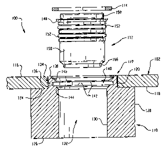
[0032] FIGURES 3 and 4 illustrate air spring and fitting assembly 100 in
further detail. More
specifically, FIGURE 3 shows bead plate 102 and a cartridge housing 110 in
cross section and prior
to assembly with a cartridge fitting 112 and a retaining member, such as
retaining ring 114, for
example. Bead plate 102 includes an outer surface or wall 116, an inner
surface or wall 118, and an
opening wall 120 forming an opening 122 through the bead plate.
[0033] Cartridge housing 110 includes a top wall 124 and an opposing bottom
wall 126. In the
embodiment shown in FIGURES 3 and 4, cartridge housing 110 is substantially
cylindrical and
includes a cylindrical side wall 128. However, it will be appreciated that any
suitable shape and/or
configuration can alternately be used. The cartridge housing also includes a
housing inner wall 130
defining a housing passage 132 extending through the cartridge housing.
Additionally, a pilot 134
projects outwardly from top wall 124 and includes a pilot side wall 136 and a
pilot end wall 138.
[0034] A plurality of geometric features and surfaces are formed along housing
inner wall 130
toward top wall 124 and pilot 134. In the exemplary embodiment shown in
FIGURES 3 and 4, a
radially outwardly extending groove 140 is formed along housing passage 132
between spaced-apart
groove walls 142. Additionally, a cartridge seating surface 144 is formed
adjacent groove 140 but
spaced therefrom toward bottom wall 126. Optionally, a feature, such as a
frustoconical relief 146,
for example, can be provided adjacent groove 140 opposite seating surface 144
that may be useful
for manufacturing or assembly purposes, such as for facilitating installation
of cartridge fitting 112
and retaining ring 114 on the cartridge housing, for example.
[0035] As can be better seen in FIGURE 4, cartridge fitting 112 is received
into cartridge passage
132 of cartridge housing 110 such that a radially outwardly extending flange
148 of cartridge body
150 engages seating surface 144 thereby supporting the cartridge fitting on
the cartridge housing.
Retaining ring 114 is fitted into groove 140 thereby capturing flange 148 and
retaining cartridge
fitting 132 within the cartridge housing. One or more sealing members, such as
o-rings 152, for
example, are sealingly positioned between cartridge body 150 and housing inner
wall 130 forming a
substantially fluid-tight seal therebetween.
-7-
CA 02609363 2007-11-22
WO 2006/127073 PCT/US2006/006390
[0036] Cartridge body 150 includes an inside wall 154 at least partially
defining a fitting passage
156 extending therethrough. A retaining collet 158 is received within fitting
passage 156, and
includes a collet base wall 160 and a plurality of retaining fingers 162. A
radially inwardly
extending projection 164 is formed on the retaining fingers and is useful for
engaging the associated
outside surface of the associated air line or supply tube. An inner support
sleeve 166 is disposed
within fitting passage 156 and is suitable for being received inside the
associated air line. A sealing
member, such as an o-ring 168, is also provided within fitting passage 156 and
is suitable for
forming a substantially fluid-tight seal between the associated outside
surface of the associated air
line and inside wall 154 of cartridge body 150. It will be appreciated that
the structure and operation
of cartridge fittings, such as cartridge fitting 112, for example, are
generally well known. One
example of a suitable cartridge fitting is commercially available under the
designation Prestomatic
Removeable Tank Cartridges from Parker Hannifin Corporation, Parker Brass
Products Division of
Otsego, Michigan.
[0037] Another embodiment of a suitable cartridge fitting 200 is shown in
FIGURE 5, and
includes a cartridge body portion 202 and a connector portion 204. Cartridge
fitting 200 is suitable
for use with a cartridge housing, such as cartridge housing 110 described
above, for example, and
will be discussed with reference thereto. Cartridge body portion 202 includes
an outer wall 206
dimensioned to be received within a housing passage, such as housing passage
132 of cartridge
housing 110, for example, and includes one or more sealing members, such as o-
rings 208, for
example, supported along outer wall 206 for forming a substantially fluid-
tight seal with an inner
wall of a cartridge housing, such as housing inner wall 130, for example. One
or more grooves 210
can optionally be provided along outer wall 206 for receiving o-rings 208.
Additionally, body
portion 202 includes a top wall 212, a bottom wall 214 and a radially
outwardly extending flange
portion 216 extending from outer wall 206 adjacent top wall 212. Flange
portion 216 is generally
suitable for engaging seating surface 144 of cartridge housing 110.
[0038] Connector portion 204 extends from body portion 202, and includes a
first section 218
and a second section 220 disposed at an angle AG1 relative to first section
218. A fitting passage
222 extends through connector portion 204 and body portion 202, and is
suitable for placing an
associated air line (not shown) secured on the connector portion in
communication with an
associated spring chamber of an associated air spring. A retaining collet 224
and a sealing member
-8-
CA 02609363 2007-11-22
WO 2006/127073 PCT/US2006/006390
(not shown) are provided on the end of second section 220 for securing the
associated air line within
the fitting passage as discussed above with regard to cartridge fitting 112,
for example.
[00391 Another embodiment of an air spring and fitting assembly 300 in
accordance with the
present novel concept is shown in FIGURE 6. Air spring and fitting assembly
300 includes an air
spring (not numbered) having a first end member, such as a bead plate 302, for
example, and a
second end member, such as a piston 304, for example, spaced from the first
end member. A flexible
wall 306 is disposed between the bead plate and piston, and can be secured
thereto in any suitable
manner. The flexible wall at least partially defines a spring chamber (not
shown) formed therewithin
between the opposing end members. A suitable mounting arrangement, such as
mounting studs 308,
for example, are provided and extend from bead plate 302. Additionally, it
will be appreciated that
the rolling lobe-type air spring shown and described herein is merely
exemplary of a suitable air
spring, and that any other suitable type, kind and/or configuration of an air
spring can alternately be
used.
[0040] As shown in further detail in FIGURE 7, bead plate 302 includes an
opening 310 formed
therethrough with a connector fitting 312 secured therealong. In the
embodiment shown in FIGURE
7, bead plate 302 is formed from substantially thin-walled sheet material
having a nominal wall
thickness that is substantially less than the length of fitting 312. As such,
opening 310 is formed
through bead plate 302 by deforming a portion of the bead plate sheet material
into a side wall 314
that defines opening 310. Thus, the side wall extends from bead plate 302 into
the spring chamber
(not shown) and terminates at an end wall 316. An alternate arrangement is
shown in FIGURE 8 in
which a bead plate 302' is formed from a material having a substantially
greater thickness than that
of bead plate 302 in FIGURE 7. This increased thickness is approximately
equivalent to the length
of side wall 314 in FIGURE 7, such that connector fitting 312 can be suitably
installed thereon.
Thus, it will be appreciated that any suitable wall thickness and/or
construction of an end member
can be used departing from the principles of the present novel concept.
[00411 Returning to FIGURE 7, connector fitting 312 includes a fitting body
318. The fitting
body includes an outer wall 320 and a radially outwardly extending flange 322
forming a shoulder
surface 324. A sealing member, such as an o-ring 326, for example, is disposed
between fitting body
318 and side wall 314 forming a substantially fluid-tight seal therebetween.
Optionally, a radially
-9-
CA 02609363 2007-11-22
WO 2006/127073 PCT/US2006/006390
inwardly extending groove 328 can be formed on the fitting body for receiving
and retaining o-ring
326.
[0042] Fitting body 318 also includes an inside wall 330 that at least
partially defines a fitting
passage 332 extending through the fitting body. An inner support sleeve 334 is
received within
fitting passage 332 and is supported therein on fitting body 318.
Additionally, a retaining collet 336
is received within fitting passage 332 and is supported on fitting body 318
toward an outer end wall
338 thereof. Collet 336 includes a collet base wall 340 and a plurality of
retaining fingers 342
extending from the collet base wall. The retaining fingers include radially
inwardly extending
projections 344 formed along the free ends thereof suitable for gripping or
otherwise interengaging
the outer surface of an associated air line. Additionally, a sealing member,
such as an o-ring 346, for
example, is disposed within fitting passage 322 between support sleeve 334 and
retaining collet 336,
and is suitable for forming a substantially fluid-tight seal between inside
wall 330 of fitting body 318
and the associated outer surface of the associated air line.
[0043] Connector fitting 312 is received in opening 310 such that one of
flange 322 and shoulder
surface 324 engage bead plate 302, which thereby prevents the connector
fitting from passing
through opening 310. To prevent the inadvertent removal of connector fitting
312 from opening 310,
a plurality of retaining members 348 extend from fitting body 318 and engage
end wall 316. In one
exemplary embodiment, the plurality of retaining members are substantially
evenly spaced around
the circumference or periphery of the fitting body. However, it will be
appreciated that any suitable
arrangement and/or configuration of retaining members can alternately be used.
The retaining
members include a first or attached end 350 extending from fitting body 318,
and a second or free
end 352 opposite the attached end. Additionally, a projection 354 extends
radially outwardly from
along the free end of the retaining members and includes a frustoconical or
otherwise tapered surface
356 and a shoulder 358 suitable for engaging end wall 316. Preferably,
retaining members 348 are
resiliently deflectable such that free ends 352 can be radially inwardly
displaced as surfaces 356
engage the bead plate during insertion of connector fitting 312 into opening
310. Once the connector
fitting has been sufficiently displaced or inserted into the opening,
projections 354 of retaining
members 348 pass through the opening beyond end wall 316 and return to a
radially outwardly
biased position in which shoulders 358 engage end wall 316 and prevent the
inadvertent removal of
the connector fitting from opening 310. An alternate embodiment of fitting
body 318 is shown in
- 10 -
CA 02609363 2007-11-22
WO 2006/127073 PCT/US2006/006390
FIGURE 9 as fitting body 318', which includes a flange 322' and a
frustoconical surface 324' instead
of the generally rectangularly shaped flange and shoulder surface of fitting
body 318.
[0044] Another alternate embodiment of an air spring and fitting assembly 400
in accordance
with the present novel concept is shown in FIGURE 10. Air spring and fitting
assembly 400
includes a bead plate 402, a mounting stud 404 and a connector fitting 406.
Bead plate 402 includes
an opening wall 408 defining an opening 410 extending through the bead plate.
Mounting stud 404
includes a flange portion 412 extending radially outwardly beyond opening 410
and forming a
shoulder 414 with a pilot portion 416 suitable for being received within
opening 410. Mounting stud
404 also includes a threaded portion 418 extending outwardly from bead plate
402 toward an end
wall 420. An inside wall 422 forms a fluid passage 424 through mounting stud
404, and includes a
radially inwardly stepped wall portion 426 forming a shoulder 428 therein.
Connector fitting 406
extends into passage 424 and engages shoulder 428 to secure the connector
fitting thereon.
Additionally, a sealing member, such as an o-ring (not shown), for example,
can be included on the
connector fitting to form a substantially fluid-tight seal along inside wall
422 within passage 424.
[0045] FIGURE 11 illustrates another embodiment of an air spring and fitting
assembly 500 in
accordance with the present novel concept. Air spring and fitting assembly 500
includes an air
spring (not shown) having an end member, such as a bead plate 502, for
example. Air spring and
fitting assembly 500 also includes a connector fitting 504 secured on the bead
plate of the air spring.
Bead plate 502 includes an outside wall or surface 506 and an opposing inside
wall or surface 508.
A passage 510 is formed through bead plate 502 by a passage wall 512. A
radially outwardly
extending retaining groove 514 is formed on passage wall 512 between groove
walls 516 and 518.
Additionally, passage wall 512 includes a sealing portion 520 that has a
reduced diameter suitable for
forming a substantially fluid-tight seal with connector fitting 504.
[0046] Connector fitting 504 includes a sensor SNR, such as a temperature,
pressure or height
sensor, for example, having a wire WRE or other electrical lead that extends
from the sensor.
Connector fitting 504 also includes a connector body 522 formed around sensor
SNR in a suitable
manner, such as by using an injection molding process to overmold the
connector body on the
sensor, for example. Connector body 522 includes a radially outwardly
extending flange portion 524
that forms a shoulder surface 526 engaging outer wall 506 of bead plate 502.
Connector body 522
also includes an elongated sealing portion 528 and a sealing member, such as
an o-ring 530, for
- 11 -
CA 02609363 2007-11-22
WO 2006/127073 PCT/US2006/006390
example, disposed along the sealing portion and forming a substantially fluid-
tight seal between
sealing portion 528 of fitting body 522 and sealing portion 520 of passage
wall 512. A groove 532
can optionally be provided along sealing portion 528 for receiving o-ring 530.
Additionally, a
plurality of retaining members 534 extend from fitting body 522 and include a
first or attached end
536 and a second or free end 538. A barb 540 is provided along free end 538
and includes a shoulder
portion 542 engaging groove wall 516 to secure connector fitting 504 on bead
plate 502. Free end
538 is resiliently deflectable to permit installation of the connector fitting
on the bead plate, and is
capable of returning to a radially outwardly biased position such that barbs
540 can engage the
opposing side of the bead plate and secure the connector fitting thereon.
[0047] Still another embodiment of a connector fitting 600 in accordance with
the present novel
concept is shown in FIGURES 12-15. It will be appreciated that certain
embodiments of the
connector fittings shown and described hereinbefore can be more difficult than
others to remove
and/or replace, after being installed on an end member of an air spring. For
example, embodiments
discussed above that include retaining members that extend axially into the
fitting passage in the end
member and include a projection or barb that engages an inner wall or surface
of the end member can
be particularly difficult to remove from the end member of the air spring.
Connector fitting 600,
however, is capable of being easily removed from an end wall of an air spring,
once it has been
installed thereon. This can be beneficial in certain applications where
inspection, repair and/or
replacement of the connector fitting and/or component thereof is desirable.
[0048] Additionally, it will be appreciated that connector fitting 600 is
shown in FIGURES 12-
15 without reference to any particular internal structure or features thereof,
and will be described
herein without any particular reference thereto. As such, it is to be
understood that connector fitting
600 is capable of broad use in a wide variety of applications and can include
any suitable internal
structure and/or components without departing from the principles of the
present novel concept. As
one example, a connector fitting adapted for easy removal from an end member,
such as connector
fitting 600, for example, could include a sensor disposed therein with a
fitting body formed
therearound, such as is shown in connector fitting 504 shown in FIGURE 11, for
example. As
another example, a connector fitting adapted for easy removal from an end
member, such as
connector fitting 600, for example, could include an inner support sleeve, a
sealing member and a
- 12 -
CA 02609363 2007-11-22
WO 2006/127073 PCT/US2006/006390
retaining collet for receiving an end of a length of associated air line, such
as is shown in connector
fitting 312 in FIGURE 7, for example.
[0049] Returning to FIGURES 12-15, connector fitting 600 includes a side wall
602 extending
between opposing end walls 604 and 606. A radially outwardly extending flange
608 includes
opposing flange walls 610 and 612, and is suitable for engaging a wall or
shoulder of an end
member, such as outside wall 506 of air spring and fitting assembly 500 in
FIGURE 11, for example.
A radially inwardly extending groove 614 is formed between end wall 606 and a
groove wall 616
spaced therefrom. Opposing flats 618 and 620 are formed along side wall 602,
and retaining
members 622 and 624 are disposed along the exterior of the connector fitting
adjacent flats 618 and
620, respectively.
[0050] Retaining members 622 and 624 each include an inner surface or wall 626
and an outer
surface or wall 628 generally opposite the inner surface or wall. Retaining
members 622 and 624 are
supported on the connector fitting at an attachment end 630 thereof and are
oriented such that the
inner walls 626 disposed toward flats 618 and 620. The retaining members are
spaced from the body
of the connector fitting such that a gap 632 is formed between flats 618 and
620 and corresponding
inner walls 626. The retaining members include a free end 634 opposite
attachment ends 630, and a
projection 636 extends radially outwardly from the retaining members along the
free ends thereof. In
one exemplary embodiment, outer walls 628 are formed with the same curvature
as the other
portions of the body. However, it will be appreciated that any suitable shape
can be used.
[0051] In use, connector fitting 600 is received on an end member of an air
spring, such as end
member 502, for example. In one exemplary embodiment, connector fitting 600 is
received in the
opening or passage formed in the end member, such as passage 510, for example,
such that flange
608 is in abutting engagement with the end member. As such, a retaining
portion 638 between the
flange and the projections is received within the fitting passage, and an
outer portion 640 extends
outwardly beyond the fitting passage of the end member. To remove the
connector fitting from the
fitting passage, free ends 634 of the retaining members are forced radially
inwardly to release
projections 636 from a suitable groove or shoulder formed along the fitting
passage. The retaining
members can be displaced in such a manner by squeezing the exposed portion of
the retaining
members extending along outer portion 640. As such, connector fitting 600 can
be selectively
removed from the end member.
- 13 -
CA 02609363 2007-11-22
WO 2006/127073 PCT/US2006/006390
[0052] The present novel concept, as shown and described with reference to the
foregoing
exemplary embodiments, can be used to overcome one or more problems and
disadvantages existing
in known constructions and arrangements. For example, the costs associated
with manufacturing
threaded components can be reduced by eliminating the threads on the fitting
and corresponding part.
As another example, the difficulties associated with installing and/or
repairing air springs, especially
in areas of reduced clearance, can also be minimized by utilizing the present
novel concept, such as
one of the foregoing embodiments, for example. That is, the elimination of the
threaded connection
coupled with the low-profile construction and push-in or snap-in design can
result in quicker and
easier installation and reduced or minimized clearance related problems.
[0053] Another advantage that is associated with the use of the present novel
concept relates to
the production and inventory of air spring components. More specifically, it
will be appreciated that
air lines of a variety of sizes are commonly used in association with air
spring assemblies. For
example, otherwise identical air springs might have different threaded
passages to receive different
sized threaded fittings, such as 3/8" NPT, 1/2" NPT, 3/4" NPT and/or similar
metric thread sizes, for
example. By utilizing a connection arrangement in accordance with the present
novel concept, air
spring components having a single diameter hole or bore can be manufactured.
Fittings having the
same external dimensions but having different sized internal arrangements to
receive different sized
tubing or sensors can be used. Thus, the number of variations of air spring
components can be
reduced.
[0054] A connector fitting adapted for use in securing an associated component
of an associated
vehicle suspension system on an associated air spring thereof is provided. The
associated air spring
having an associated spring chamber formed between a spaced-apart pair of
associated end members
with one of the associated end members having an associated outer wall, an
associated inner wall and
an associated passage wall defining an associated fitting passage in
communication with the
associated spring chamber, said connector fitting comprising: a fitting
housing dimensioned to be
received within the associated fitting passage of the associated end member,
said fitting housing
including an outer housing wall and an inner housing wall, said inner housing
wall at least partially
defining a housing passage extending through said fitting housing for
supporting the associated
component in communication with the associated spring chamber, and said outer
housing wall
including a radially outwardly extending support surface adapted to engage one
of the associated
- 14 -
CA 02609363 2007-11-22
WO 2006/127073 PCT/US2006/006390
outer wall and the associated passage wall of the associated end member; a
sealing member sealingly
supported between said fitting housing and the associated passage wall; and a
plurality of elongated
retaining members extending from said fitting housing, said plurality of
retaining members including
a first end extending from said fitting housing and a second end capable of
resilient deflection, said
second end including a projection suitable for engaging one of the associated
inner wall and the
associated passage wall.
[0055] A connector fitting according to the foregoing paragraph, wherein said
support surface
includes a frustoconical portion.
[0056] A connector fitting according to the foregoing paragraph, wherein said
fitting housing
includes a plurality of flats, and said retaining members are disposed along
said flats in spaced
relation to thereto.
[0057] A connector fitting according to the foregoing paragraph, wherein said
fitting housing
includes an outer end wall and an inner end wall, and said first end of said
retaining members is
disposed along said outer housing wall toward said outer end wall with said
support surface being
disposed along said fitting housing between said first end of said retaining
member and said inner
end wall.
[0058] An air spring assembly is provided and comprises a first end member
including a first
side, an opposing second side and a substantially smooth-walled fluid passage
extending
therethrough; a second end member in spaced relation to said first end member;
a flexible wall
secured between said first and second end members and at least partially
defining a fluid chamber in
communication with said fluid passage; a connector fitting for retaining an
associated fluid line in
communication with said fluid chamber, said connector fitting being supported
on said first end
member along said fluid passage, said connector fitting including: a fitting
body including a support
surface and a body wall, said body wall at least partially defining a body
passage, said fitting body
being at least partially received in said fluid passage such that said support
surface engages at least a
portion of said first end member; a retaining collar received in said body
passage and adapted to
engage an associated exterior surface of the associated fluid line; an inner
support sleeve received in
said body passage adjacent said retaining collar and adapted to engage an
associated interior surface
of the associated fluid line; a first sealing member compressively positioned
between said fitting
body and said first end member; and a second sealing member disposed within
said body passage
- 15 -
CA 02609363 2007-11-22
WO 2006/127073 PCT/US2006/006390
and compressively positioned between said fitting body and the associated
exterior surface of the
associated fluid line; and a retaining member adapted to engage said first end
member to retain said
connector fitting thereon.
[0059] An air spring assembly according to the foregoing paragraph, wherein
said first and
second retaining members include outwardly extending projections disposed
along said second end,
said projections being capable of engaging said first end member and retaining
said connector fitting
thereon.
[0060] An air spring assembly according to the foregoing paragraph, wherein
said fitting body
includes a longitudinally extending groove and one of said first and second
retaining members is
disposed along said groove.
[0061] An air spring assembly according to the foregoing paragraph, wherein
said fitting body
includes an inner end wall and an outer end wall, and said first end of said
retaining members is
disposed along said fitting body toward said outer end wall with said support
surface longitudinally
disposed along said fitting body between said first end of said retaining
members and said inner end
wall.
[0062] An air spring assembly adapted to receive an associated cartridge
fitting suitable for
securing an associated air line on said air spring assembly is provided. The
air spring assembly
comprising: a first end member including a first outer wall, an opposing first
inner wall and an end
member opening extending through said first end member, said first end member
having a
substantially uniform first end member thickness along said end member
opening; a second end
member including a second outer wall and an opposing second inner wall, said
second end member
being spaced from said first end member and oriented such that said second
inner wall is disposed
toward said first inner wall; a flexible wall secured between said first and
second end members and
at least partially forming a spring chamber between said first and second
inner walls thereof; a
cartridge housing secured along said first inner wall of said first end member
within said spring
chamber, said cartridge housing including a housing passage extending
therethrough, said housing
passage being accessible through said end member opening for receiving the
associated cartridge
fitting.
[0063] An air spring assembly according to the foregoing paragraph, wherein
said cartridge
housing includes a first side wall, an opposing second side wall and pilot
extending outwardly from
- 16 -
CA 02609363 2007-11-22
WO 2006/127073 PCT/US2006/006390
first side wall, said pilot having a height that is less than or equal to said
first end member thickness
and that is received into said end member opening such that said pilot extends
substantially evenly
with or is recessed below said first outer wall.
[0064] An air spring assembly according to the foregoing paragraph, wherein
said pilot is
substantially cylindrical and extends substantially coaxially with said
housing passage.
[0065] An air spring assembly according to either of the two foregoing
paragraphs, wherein said
housing passage is formed such that the associated cartridge fitting extends
substantially evenly with
or is recessed below said first outer wall of said first end member.
[0066] While the subject novel concept has been described with reference to
the foregoing
embodiments and considerable emphasis has been placed herein on the structures
and structural
interrelationships between the component parts of the embodiments disclosed,
it will be appreciated
that other embodiments can be made and that many changes can be made in the
embodiments
illustrated and described without departing from the principles of the subject
novel concept.
Obviously, modifications and alterations will occur to others upon reading and
understanding the
preceding detailed description. Accordingly, it is to be distinctly understood
that the foregoing
descriptive matter is to be interpreted merely as illustrative of the present
novel concept and not as a
limitation. As such, it is intended that the subject novel concept be
construed as including all such
modifications and alterations insofar as they come within the scope of the
appended claims and any
equivalents thereof.
- 17 -