Note: Descriptions are shown in the official language in which they were submitted.
CA 02609803 2007-11-19
WO 2006/123199 PCT/IB2005/001794
Multiple Chilled Alcoholic Beverages Dispenser System
The present invention relates to a dispenser system for dispensing multiple,
chilled alcoholic beverages. Dispensing systems for alcoholic beverages have
been known.
for a long time, and many solutions have previously been proposed to try and
solve the
problems associated with chilling and maintaining the temperature of the
chilled alcoholic
beverage so that the customer obtains a satisfacforily chilled drink. Such
systems have
previously been known to include a source of alcoholic beverage, a chilling
means, and a
means for dispensing the chilled beverage.
Generally, the source of alcoholic beverage is supplied in a suitable
container,
for example in a bottle, a canister, or "bag-in-box", i.e. a box-like outer
structure offen
made of cardboard, and comprising a flexible envelope located within the
cardboard outer,
and within which envelope the alcohol beverage, for example wine, is stored.
Classically, the beverage has been known to be chilled after dispensing by
direct chilling, for example, by the addition of ice cubes to the beverage
once poured.
Other methods of chilling are also known, for example, by placing the
container in which
the alcoholic beverage is stored into a domestic or industrial refrigerator
chamber, and
then withdrawing the beverage from the container upon demand. The problems
associated
with such a means of chilling and dispensing are also well known, in that,
repeated
withdrawal of the container from the refrigerafor chamber causes the
temperature of the
alcoholic beverage to rise the more often that drink is dispensed. Such a
solution also has
the inherent problems associated with storage of the beverage in a location
that may be
needed for storage of other products such as food.
Another solution, for example, in the case of beer, has been to provide the
beer in a vat under pressure. The beer, often stored in a beer cellar, is
connected via
conduifs to a pump, and the connecting conduits may or may not be
refrigerated. When
several beers are to be proposed, it is often necessary for each one to have a
separate
pump and a separate refrigerating mechanism so that the beers are not mixed
and can be
served at a correctly chilled temperature. This adds to the complexity and
maintenance of
such systems, but also does not necessarily guarantee that the beer is served
at the
correct temperature, depending on the distance that the beer has to travel
from the
container to the dispenser.
I
CA 02609803 2007-11-19
WO 2006/123199 PCT/IB2005/001794
One way around these problems has been to propose all-in-one devices that
cool the beverage. For example, with bag-in-box solutions, such dispensers
generally
comprise a small refrigerafing unit disposed above or below the outer box
sfrucfure, and
through which the beverage is made to pass or is with which the beverage is
brought into
contact in order to chill the alcoholic beverage, which in this case is most
often wine. In
this way, the wine can be chilled before serving simply by placing the box in
position onto
or beneath the refrigeration unit. There still remains, however, the problem
of providing a
dispenser that can store multiple alcoholic beverages, provide refrigeration
for said
beverages, and provide disfribufion of said beverages, all in one single,
compact
apparatus, that can be sat on top of a bar surface, for example.
The present inventors have surprisingly discovered that it is possible to
provide
a dispenser system for chilled alcoholic beverages that will permit dispensing
of two or
more alcoholic beverages at the same time, and which remains nonetheless
compact,
easy to maintain, and easy to operate, while providing the alcoholic beverages
at the
desired chilled temperature.
Consequently, one objecf of the present invention is a multiple chilled
alcoholic
beverages dispenser system comprising :
- at least two independent sources of alcoholic beverage each
stored in a separate container;
- a cooling system through which the at least two independent
sources of alcoholic beverage pass before dispensing; and
- dispenser means,
- wherein the cooling system comprises a single chamber
through which the at least two independent sources of alcoholic
beverage pass before reaching the dispenser means.
Preferably, the at least two independent sources of alcoholic beverage are
selected from the group consisting of bottles, canisters, sachets, cans,
boxes, and are
preferably both bottles.
In yet another preferred embodiment of the invention, the single chamber of
the cooling system comprises an ice bank generator as primary source of cold,
preferably
an evaporator. Even more preferably, the single chamber of the cooling system
contains at
2
CA 02609803 2007-11-19
WO 2006/123199 PCT/IB2005/001794
least one eutectic solution with a freezing point comprised befween about - 4
Cfo about
- 20 C Eutectic solutions that freeze at this temperature are well known in
the art, and
commercially available. Examples of such a solution are Temper -10 C or Temper
-20 C;
distributed by Dehon, France. The evaporator coil is preferably located at the
bottom of the
single chamber, with the major volume of the chamber located above it. When
the
evaporator coil is brought into operation, ice tends to form above or around
the coil, in
what is known as an ice bank. The ice bank is made up of crystals of at least
one frozen
eutectic solution. The remainder of the at least one eutectic solution that is
still in liquid
form in the chamber is preferably circulated over the ice bank that forms,
thereby
maintaining a low temperature of said solution. In order to circulate said
solution within the
chamber, two pumps are most preferably provided that cause the solution to be
directed
over the bank of ice located above the evaporator coil at the bottom of the
chamber, and
from there into an upper zone of the cooling chamber.
In another preferred embodiment, the single chamber of the cooling system
comprises a Peltier plate. These are thermoelectric devices, also well known
per se in the
art, that produce a temperature differential via metals having different
electrical resistances
or conductivities. The Peltier plate can also be located at the bottom of the
single chamber,
the coldest face of the plate facing upward toward the major volume of the
chamber. Since
one side of the plate is much colder than the other, ice tends to form on that
side of the
plate, as an ice bank, in a similar manner to the evaporafor coil.
In still yet another preferred embodiment, the beverage sources each have an
outlet that is located at a position above an uppermost limit of the cooling
system. In this
way, the beverages can simply leave the beverage source under the effect of
gravity.
However, in a most preferred embodiment, the beverage sources are forced into
the
cooling system by forced introduction of air into the beverage sources. Such
forced
introduction of air into the beverage sources can be provided by at least one
air pump,
preferably an air pump for each beverage source. In this way, when beverage is
to be
introduced into the cooling system, air is forced into the beverage source,
for example a
bottle, and the pressure increase within the bottle causes the beverage
therein to be
forced oaf into the cooling system.
In another even more preferred embodiment, each beverage source is
connected to a separate cooling coil, and each separate coil passes flirougti
the single
3
CA 02609803 2007-11-19
WO 2006/123199 PCT/IB2005/001794
chamber. In this manner, each beverage is cooled in a separate cooling circuit
that is
located in the single cooling chamber. The cooling coils are located in the
single chamber
above the evaporator coil or Peltier plate, and therefore above the ice bank
that forms
within the chamber. In a most preferred embodiment of the invention, and one
that has
been found to be particularly advantageous, the cooling coils are arranged
side by side in
the cooling chamber, i.e. each coil occupies approximafely half of the free
volume
remaining in the chamber. It is to be understood in the present specification
that the "free
volume" of the cooling chamber refers to the total volume minus the volume
occupied by
the evaporator coil or Peltier plate and the ice bank. In order to facilitate
location of the
cooling coils in the single chamber, a shoulder or baffle can be provided in a
lower zone of
said chamber that projects from one of the peripheral walls of said chamber
into said
chamber, but which still leaves access to the evaporator coil or Peltier plate
located at the
bottom of said chamber. In this way, the cooling coils can simply rest on the
shoulder or
baffle plate and do not need to be maintained or suspended by brackets or
other
suspension means. Alternatively and in another embodiment, the cooling coils
can be
arranged coaxially, a first inner coil being located with the volume defined
by a second,
outer coil, along a vertical or horizontal axis of the single chamber.
Preferably, the beverage sources used in the invention are bottles and are
connected via a respective and corresponding feed tube to the cooling coils
passing
through the cooling system. Even more preferably, an air filter for and
connected to each
feed tube is provided, enabling air to enter each respective bottle when
beverage leaves or
is withdrawn from the bottles. A non-return valve is preferably also provided
between the
air filter and the feed tube, thereby preventing any beverage from reaching
the air filter.
In still yet another preferred embodiment, a female-female adapter is fitted
sealingly around and over the feed tube at one extremity of said adapter, and
sealingly
receives a bottle neck and head of the beverage source at the other extremity
of said
adapter. The female-female adapter sealing engages the bottle neck and head,
thereby
preventing beverage from escaping to any undesirable location outside of the
system. A
tight seal can be ensured by providing one or two, preferably two, 0-ring
seals within the
extremity of the adapter that receives the bottle neck and head. The adapter
is fitted with a
mechanism to control beverage flow into the cooling system, for example, by
providing a
ball valve mechanism. Other valves could also be envisaged, for example,
electrically
4
CA 02609803 2007-11-19
WO 2006/123199 PCT/IB2005/001794
actuated valves, or other well known types of membrane that function in an
equivalent
manner.
In order to maintain a tight and correct connection between the female-female
adapter and the bottle, a threading can preferably be located within the
adapter or within
the integrated sleeve of the feed tube. This threading can correspond to the
equivalent
screw threading that is provided on many bottle necks or other containers,
such as certain
drink canisters, thereby enabling the bottle, canister or container equipped
with a screw-
threaded head to be screwed into place in the adapter, limiting movement
thereof and
improving the seal between the container and the adapter.
In an alternative and preferred embodiment, the feed tube comprises an
integrated outer sleeve connected to an annular base skirt, and an inner
sleeve that
sealingly receives a bottle neck and head. In such an embodiment, there is no
longer any
female-female adapter, and the feed tube connects directly with the bottle.
The oufer
sleeve extends from the base skirt that is located substantially half-way
along the length of
the feed tube. The inner sleeve does not need to be equipped with a screw
thread for
receiving beverage source. The outer sleeve can additionally and preferably
have an
annular inward projection or lip, that is even more preferably angled, to
guide the beverage
source container, for example, a bottle neck, into a mating configuration
within the inner
sleeve, and to prevent any splashing or spilling of beverage outside of the
feed tube. The
feed tube also preferably comprises a bevelled piercing tip located within the
inner sleeve,
and which is aligned in an axial extension of said feeder tube. The inner
sleeve extends
beyond the bevelled piercing tip so as to form a tight seal with the bottle
neck by means of
0-ring seals provided within the inner sleeve. The annular lip at of the outer
sleeve helps
to guide the bottle neck onto the piercing tip. The alternative feed tube
embodiment is
particularly useful when the bottle has a cap and a tamper membrane located
across the
opening of the bottle and placed between the cap and said opening in order to
maintain
hygiene and show that the bottle has not been tampered with before use. In use
the cap is
removed, and the bottle inserted into the into outer, and then inner sleeve.
The bottle head
and neck will slide into the inner sleeve, guided by the annalar lip of the
outer sleeve, until
the head comes to rest on an annular shoulder connecting the feeder fube to
the inner
sleeve. the 0-ring seals present, preferably two 0-ring seals, will provide
for elastic
sealtight maintenance of the bottle in position. Since the feed tube comprises
a bevelled
CA 02609803 2007-11-19
WO 2006/123199 PCT/IB2005/001794
piercing tip, the tip will come info.confacf with the membrane and pierce the
latter thereby
enabling fluid connection between the feed tube and the beverage source.
The present invention will now be described in more detail with reference to
some preferred modes of execution, and the drawings, in which :
- Figure 1 represents a rear perspective view of a preferred chilled alcoholic
beverage
dispenser system according to the invention;
- Figure 2 represents a cross-sectional view of the dispenser of Figure 1;
- Figure 3 represents a top perspective view of the dispenser of Figure 1 with
a cooling
system cover plate removed;
- Figure 4 represents substantially the same view as Figure 3, except that the
cooling
coils have been removed to display the ice bank generator as the primary
source of cold
at the bottom of the cooling chamber;
- Figure 5 represents a particularly preferred alternative embodiment of the
feeder tubes
used in the system of the present invention;
- Figures 6 and 7 represent respectively a cross-sectional view of a detail of
the feeder
tube of Figure 5 along its longitudinal axis, and a cross-sectional view
orthogonal to the
longitudinal axis of the tube, i.e. the appearance of the tube when looking
from above
down through said tube.
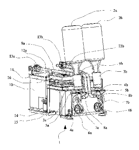
Turning now to Figure 1, a chilled alcoholic beverage dispenser system
according to the invention is represented generally by the reference numeral
1. The
dispenser comprises two alcoholic beverage sources 2a, 2b, in this case two
bottles of
alcohol, for example, spirit, fortified wine, beer, or the like, that are
located substantially
above the dispenser 1. The bottles are connected to the dispenser 1 via an
adapter 3a, 3b,
in which the necks of the bottles are received in a sealtight manner. The
adapters 3a,3b
are in turn connected to feed fubes 4a,4b. The feed tubes have a base skirt
5a,5b located
approximately half-way along the length of the tube, which provides a stop for
the sliding
insert of the adapters 3a,3b onto the tubes 4a,4b. The feed tubes 4a,4b are
connected to
corresponding air filters 6a,6b and ducts 7a,7b, enabling filtered air to
enter the bottles
2a,2b via the feed tubes 4a,4b and adapters 3a,3b. Preferably, non-return
valves are
provided between the air filters 6a,6b and the ducts 7a,7b. The feed tubes
4a,4b are also
connected to beverage oufief ducts 8a,8b, that carry the beverages separately
and
6
CA 02609803 2007-11-19
WO 2006/123199 PCT/IB2005/001794
independently to separate cooling coil inlets 9a,9b. These cooling coil inlets
then
disappear info a cooling chamber 10, in which the cooling system and cooling
coils are
located. The cooling chamber 10 has a removable cover plate 11, to facilitate
access to
the chamber and thereby maintenance of the cooling coils, primary cold source
generator,
and eutecfic solutions stored therein. Two chilled beverage outlet ducts
12a,12b emerge
through the cover plate 11 and are connected to two corresponding electrically
actuated
valves 13a,13b.
The valves 13a,13b are connected to taps or spigots (not shown) and are
actuated when it is desired to dispense one or more of the chilled alcoholic
beverages.
Alternatively, the valves can also be replaced by a nip feed system, that can
either be
manual, i.e. mechanical, or electrically actuated, whereby the chilled
beverage passes
through a duct that can be opened or closed as desired using, for example, a
nip roller
mechanism. Typically in such a mechanism, a first roller is brought to impinge
on another
roller or pair of rollers thereby blocking flow of beverage. Equivalent
systems using metal
or plastic blocks that interlock are also known and can be used instead of the
roller
mechanism. Also shown in Figure 1 is a pump 14, that circulates eufecfic
solution within
the cooling chamber, and a base plate 15 to which forms the foundation for the
dispenser
according to the present invention, and to which the major components are
directly
attached. A control uriif 16 is provided that deals with regulating the
temperature, and
controlling the electrical circuitry of the device, including, for example,
tracking the number
of beverage doses dispensed, maintenance intervals, and the like.
Figure 2 is a cross-section of the system represented in Figure 1. The same
references designate the same elements of Figure 1 except that no
differentiation is made
between an element (a) or (b) of the same reference numeral. The adapter 3 is
fitted with
0-ring seals 17 to ensure a sealtight fit of the bottle 2. In addition, a
suspended flexible
membrane 19 fitted with a ball 18 forms a valve in the adapter 3 enabling
regulation of the
flow of beverage info the feeder tube. The bottle head rests on an annular
shoulder 31 that
projects from the adapter wall into the adapter volume, leaving an opening
that
corresponds in diameter substantially to that of the opening of the boffle. In
this way,
alcoholic beverage from the bottle does not flow all over the inside of the
adapter or leak
out. This is a particularly advantageous configuration for alcoholic beverages
with a
relatively high sugar content, such as in fortified wines, since it
effectively avoids
7
CA 02609803 2007-11-19
WO 2006/123199 PCT/IB2005/001794
deposition of excess beverage in the adapter, thereby avoiding build up of
sirupy residues
that could make it difficult to fit subsequent bottles onto the adapter. This
figure also
illustrates the presence of air pumps 33a,33b, which are connected to the air
filters 6a,6b
respectively, and enable filtered air to be forced into the beverage sources
via the feed
tubes 4a,4b, for example bottles, thereby forcing beverage back into the feed
tubes and
into the cooling system via outlets 8a,8b, and inlets 9a,9b.
The beverage from the bottle flows down through the adapter 3, through the
feeder tube 4 and into the outlet 8. This outlet is conriecfed to the cooling
coil inlet 9, which
is in turn connected to a cooling coil 29. Each cooling coil 29 is located in
the cooling
chamber 10 and rests substantially on a shoulder 28 provided in the chamber
that projects
into the volume of said chamber. The shoulder 28 also helps keep the cooling
coils 29
separated from the ice bank that forms in the eutectic solution. The chamber
is also
equipped with a primary cold source generator 27, in this example an
evaporator coil 27
that is connected to a compressor 23. The evaporator coil 27 generates a
source of
primary cold, that in turn cools the eutectic solution held within the
chamber. Directly
above the evaporator coil 27, an ice bank tends to form and this accentuates
the transfer
of cold with the eutectic solution which is cause to circulafe around the
chamber 10 by
means of a pump 14. The pump 14 withdraws eutectic solution from the chamber
10 via a
duct 24 and an outlet orifice 32 (see Figure 4) located near the bottom of the
chamber 10.
The eutectic solution is then pumped back into the chamber 10 via duct 24 and
inlet orifice
30, located at a position higher up in the chamber, and preferably, as
illustrated in Figures
3 and 4, located in the shoulder 28. In this manner eutectic solution is
circulated in the
chamber from the bottom to the top, causing a flow of colder eufecfic solution
to move over
the cooling coils 29. As energy is exchanged with the cooling coils, so the
beverage cools,
and so the eufecfic solution should warm up. However, since the eutectic
solution is
pumped around the chamber and is in continuous contact with the ice bank, it
remains at
substantially the same temperature throughout.
Figure 3 shows a top perspective view of the system illusfrated in Figure 1
with
the cover plate removed so that the cooling coils 29a,29b, and the evaporator
27 are
visible. From this Figure, one can see how the cooling coils 29a,29b are
located side by
side in the chamber 10, and how they rest on the shoulder 28, which
effectively projects
into the volume of the chamber from one of the peripheral walls of the latter,
effectively
8
CA 02609803 2007-11-19
WO 2006/123199 PCT/IB2005/001794
separating the evaporator 27 from the cooling coils, so that they do not come
into direct
contact with each other, and still leaving enough volume for an ice bank to
form and permit
circulation of eutectic solution.
Figure 4 illustrates the same system as in Figure 3, but with the inlet ducts
9a,9b and coils 29a,29b removed, as would be the case for example, when
maintenance
is carried out on the system. One can easily comprehend that the system is
also easy to
maintain and highly modular.
Figure 5 illustrates a cross-section of a particularly preferred alternative
embodiment of the feeder tube used in the system of the present invention and
generally
indicated by the reference numeral 4. The feeder tuber 4 can be made of molded
plastic,
for example, polyethylene, polypropylene, or any other suitable plastic
material that is
suitable for contact with alcoholic beverages, and comprises an annular base
skirt 5, a
feed tube proper 410, the lower extremity 417 of which is closed. The feed
tube 410 has a
beverage outlet 8, through which beverage flows to the cooling system of the
dispenser of
the invention. The tube 410 extends upwards towards, through, and above ffie
base skirt
5, and comprises an annular shoulder 418, connected to the tube 410, that
rests on the
base skirt 5. The feeder tube 4 comprises two sleeves, an outer sleeve 415
connected or
integrated to the annular base skirt 5, which projects upwards from the
periphery of the
skirt 5 over. At an upper extremity of the oufer sleeve 415 there is an
annular lip 414 that
may be angled downwards towards an inner sleeve 416 of the feeder fube. The
inner
sleeve 416 extends upwards from the annular shoulder 418, towards the annular
lip 414 of
the outer sleeve 415. The purpose of the annular lip 414 is to help guide and
stabilize a
bottle neck that is being inserted onto the feeder tube. It also serves to
help position the
bottle head 419 within the inner sleeve 416. The inner sleeve is provided with
two 0-ring
seals 412, 413, located on the inner wall 420 of said sleeve 416. Formed
within the tube
proper 410 is a bevelled piercing tip 411. As the bottle head 419 is engaged
in the inner
sleeve, so the piercing tip will pierce a membrane 421 that can be provided on
the bottle
head to demonstrate that the bottle has not been tampered with. When the tip
411 pierces
the membrane 421, the membrane is broken and beverage will now be able to flow
into
the feed tube 410 and into the cooling system via oufief 8. In the preferred
embodiment of
the invention, this occurs when the electrically actuated valve 13 is actuated
by an
operator, which in turn activates the air pump 33, injecting air via the air
filfer 6 into the
9
CA 02609803 2007-11-19
WO 2006/123199 PCT/IB2005/001794
bottle 2, thereby flushing beverage into the feeder tube and cooling sysfem.
Figures 6 and 7 are different cross-sections of the inner sleeve of the feeder
tube of Figure 5, and show the arrangements of an air inlet 422 and air inlet
conduit 423
within the feeder tube 410 and the beverage conduit 424 and beverage outlet 8.