Note: Descriptions are shown in the official language in which they were submitted.
CA 02609991 2012-10-31
APPARATUS, SYSTEM, AND METHOD FOR
TREATMENT OF POSTERIOR LEAFLET PROLAPSE
CROSS-REFERENCES TO RELATED APPLICATIONS
[0001]
FIELD OF THE INVENTION
[0002] The present invention relates generally to medical devices and
particularly
to repairing posterior leaflet prolapse in a mitral valve.
BACKGROUND OF HE INVENTION
[00031 In vertebrate animals, the heart is a hollow muscular organ
having four
pumping chambers: the left and right atria and the left and right ventricles,
each provided with
its own one-way valve. The natural heart valves are identified as the aortic,
mitral (or bicuspid),
tricuspid, and pulmonary, and are each mounted in an an.nulus comprising dense
fibrous rings.
The mitral and tricuspid valves have thread-like bands of fibrous tissue that
attach to the valve
at one end and to the papillary muscles at the other end.
[0004] Heart valve disease is a widespread condition in which one or
more of the
valves of the heart fails to function properly. Diseased heart valves may be
categorized as either
stenotic, wherein the valve does not open sufficiently to allow adequate
forward flow of blood
through the valve, and/or incompetent, wherein the valve does not close
completely, causing
excessive backward flow of blood through the valve when the valve is closed.
Valve disease can
be severely debilitating and even fatal if left untreated.
CA 02609991 2012-10-31
[0005] Various surgical techniques may be used to repair a diseased or
damaged
valve. One method for treating defective valves is through repair or
reconstruction. One repair
technique that has been shown to be effective in treating incompetence is
annuloplasty, in
which the effective size and/or shape of the valve annulus is modified by
securing a repair
segment, such as an annuloplasty ring, around the heart valve annulus. For
example, the valve
=lulus may be contracted by attaching a prosthetic annuloplasty repair segment
or ring to an
interior wall of the heart around the valve annulus. The annuloplasty ring is
designed to
support the functional changes that occur during the cardiac cycle:
maintaining coaptation and
valve integrity to prevent reverse flow while permitting good ktemodynamics
during forward
flow.
[0006] The annuloplasty ring typically comprises an inner substrate,
often formed
from a metal (such as stainless steel or titanium) or from a flexible material
(such as silicone
rubber or Dacron cordage), which is typically covered with a biocompatible
fabric or cloth to
allow the ring to be sutured to the heart tissue. Depending on a particular
application,
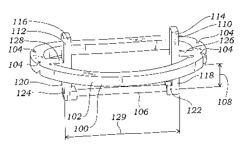
annuloplasty rings may be stiff or flexible, may be split or continuous, and
may have a variety
of shapes, including circular, 1D-shaped, C-shaped, saddle-shaped, and/or
kidney-shaped.
Examples are seen in US. Pat. Nos. 5,041,130, 5,104,407, 5,201,880, 5,258,021,
5,607,471,
6,187,040, and 6,805,710. Many annuloplasty rings are formed in a plane, but
some rings are
generally non- planar. Such non-planar rings can be saddle-shaped, and/or
bowed along
various portions, such as being bowed along their anterior or straight side to
conform to the
desired shape of the annulus at that location.
[0007] In many diseased valves, the chordae tendineae are either
ruptured,
otherwise damaged, or of an improper length. When chordae
CA 02609991 2007-11-26
WO 2007/002627
PCT/US2006/024889
3
conform to the desired shape of the annulus at that location.
[0007] In many diseased valves, the chordae tendineae are either
ruptured, otherwise damaged, or of an improper length. When chordae
tendineae are too long, too short, or otherwise damaged, the corresponding
tricuspid or mitral valve to which they are attached typically may fail to
close
properly. For example, chordae tendineae which are ruptured or are too long
allow a valve to prolapse, wherein one or more valve leaflets swing backward
past their proper closed position. This can lead to regurgitation, which is
the
unwanted backflow of blood from a ventricle to an atrium resulting from
imperfections in the valve. When the valve allows such backward flow into an
atrium, the corresponding ventricle must pump progressively harder to
circulate blood throughout the body, which in turn promotes congestive heart
failure.
[0008] Repairing and/or replacing dysfunctional chordae tendineae has
been performed for some time. The techniques for such repair are often
complicated due to the difficulties in accessing the surgical site, in
identifying
the dysfunctional chordae tendineae, and in determining the proper length for
the repaired and/or replacement chordae tendineae.
[0009] Another approach to valve repair involves surgical excision of
all or a portion of one or more of the valve leaflets of the particular heart
valve. In such a procedure, a damaged portion of a valve leaflet is excised,
with the remaining portions of the valve leaflet stitched together to repair
the
opening created by the removal of the damaged portion. This procedure
tightens the valve leaflet, which can prevent valve prolapse and thereby
improve valve function. An example of such a procedure is a segmental
6426_1 ECV-5845 PCT
CA 02609991 2007-11-26
WO 2007/002627
PCT/US2006/024889
4
resection of the mitral valve, wherein a prolapsing portion of a posterior
leaflet
is excised and the remaining portions sewed together to tighten the leaflet.
[0010] Quadrangular resection of the prolapsed area is a relatively
common valve repair technique which has demonstrated excellent results.
However, the technique is relatively complex and can require the surgeon to
make numerous real-time decisions during the course of the procedure,
including determining how large to make the resection, whether to perform an
annulus plication to close the gap, etc.
[0011] The goal of mitral valve repair is to restore a good surface
of
coaptation to ensure satisfactory function of the valve. Because leaflet
tissue
is the primary component defining the surface of coaptation of the valve, it
may be preferable to preserve as much as possible of the leaflet tissue, as
opposed to resecting significant portions thereof. Preserving as much tissue
as
possible maintains anatomic and dynamic relationships, allowing for better
distribution of forces and stresses on the valve components. However, in
order to preserve the leaflet tissue, other aspects of the dysfunctional valve
may have to be modified and/or treated, such as the shape of the valve annulus
and any damaged chordae.
[0012] Accordingly, there has been a need for an improved apparatus,
system, and method to repair dysfunctional heart valves, including mitral
valves. The present invention satisfies one or more of these needs.
SUMMARY OF THE INVENTION
.6426_1 ECV-5845 PCT
CA 02609991 2007-11-26
WO 2007/002627
PCT/US2006/024889
[0013] The present application is generally described with respect to
its use in the repair of the mitral valve, which regulates blood flow from the
left atrium (LA) to the left ventricle (LV). However, the invention could also
be applied to repair of other valves, such as the tricuspid or aortic valve
5 repairs.
[0014] The invention includes correction of mitral valve prolapse
using replacement chordae, such as expanded neochordae suture (such as
ploytetrafluroethylene (e-PTFE)) without leaflet resection, or with minimal
leaflet resection, to resuspend the free edge of the posterior leaflet. One or
more replacement chordae sutures can be passed through the papillary muscle
and through the leaflet, adjusted to the proper length, and tied in position.
The
desired number and length of the replacement chordae depends on the needs of
the particular patient, including characteristics of the valve annulus, the
valve
leaflets, and the existing chordae.
[0015] The invention can include application of a heart valve
annuloplasty ring. The annuloplasty ring can reshape the heart valve annulus
to a desired shape, and/or prevent the heart valve annulus from further and
undesired deformation. The annuloplasty ring can also fix the valve annulus
in the systolic position.
[0016] The invention can also include modifications to the valve
leaflet itself. For example, the surgeon may suture the indentations on the
valve leaflet, particularly where the indentations are relatively deep and
where
an annuloplasty ring is used to fix the valve annulus in the systolic
position.
[0017] Various aspects of the invention can be used individually or
in
combination to repair a valve. The invention is applicable to various ways of
6426_1 ECV-5845 PCT
CA 02609991 2007-11-26
WO 2007/002627
PCT/US2006/024889
6
accessing the valve for repair, including an open surgical approach such as
sternotomy, or a minimally-invasive approach such as percutaneous or
intercostal. The standard atriotomy approach is often used for mitral valve
repair procedures.
[0018] Other features and advantages of the present invention will
become apparent from the following detailed description, taken in conjunction
with the accompanying drawings which illustrate, by way of example, the
principles of the invention.
BRIEF DESCRIPTION OF THE DRAWINGS
[0019] Figure 1 depicts a top view of a mitral valve being exposed
for
viewing and analysis by the surgeon;
[0020] FIG. 2 depicts a top view of a mitral valve being analyzed by
a
surgeon;
[0021] FIG. 3 depicts a top view of a mitral valve under analysis of the
prolapsed area of the mitral valve posterior leaflet;
[0022] FIG. 4. depicts a top view through a mitral valve with
placement of artificial chordae suture through the papillary muscle;
[0023] FIG. 5A depicts a top view of a mitral valve with placement of
artificial chordae suture through the free edge of the posterior leaflet;
6426_1 ECV-5845 PCT
CA 02609991 2007-11-26
WO 2007/002627
PCT/US2006/024889
7
[0024] FIG. 5B depicts a side view of a mitral valve with placement
of
artificial chordae suture through the free edge of the posterior leaflet;
[0025] FIG. 6A is a side view of a mitral valve and papillary muscle
with placement and tying of artificial chordae suture where there is no
significant excess of tissue;
[0026] FIG. 6B is a side view of a mitral valve and papillary muscle
with placement and tying of artificial chordae suture where there is an excess
of tissue;
[0027] FIG. 7 is a side view of a mitral valve and papillary muscle
with tying of the artificial chordae suture;
[0028] FIG. 8 is a top view of a mitral valve with sutures applied to the
posterior leaflet indentations;
[0029] FIG. 9 is top view of a mitral valve with an annuloplasty ring
implanted and with a saline injector;
[0030] FIG. 10 is a top perspective view of a guide device according
to
an embodiment of the invention;
[0031] FIG. 11 is a side perspective view of the guide device of FIG.
10;
[0032] FIG. 12 is a top view of the guide device of FIGS. 10-11
positioned on or in a mitral valve annulus according to an embodiment of the
invention;
6426_1 ECV-5845 PCT
CA 02609991 2007-11-26
WO 2007/002627
PCT/US2006/024889
8
[0033] FIG. 13 is a side perspective view, in partial cross-section,
of
the guide device of FIGS. 10-11 positioned on or in a mitral valve annulus
according to an embodiment of the invention;
[0034] FIGS. 14A-14C are side views in partial cross section of a
guide device according to an embodiment of the invention;
[0035] FIG. 15 is a side view in partial cross section of a guide
device
according to an embodiment of the invention;
[0036] FIGS. 16A and 16B are side views in partial cross section of a
guide device according to an embodiment of the invention; and
[0037] FIGS. 17A and 17B are side views in partial cross section of a
guide device according to an embodiment of the invention.
DETAILED DESCRIPTION OF THE INVENTION
[0038] FIG. 1 depicts a heart 10 with an incision 12 in the left
atrial
wall 14 through which the mitral valve 16 is exposed for viewing during a
surgical proceeding. The atrial wall incision 12 is held open with one or more
retractors 18, giving the surgeon a full view for analysis of the mitral valve
16.
Note that the viewing can be achieved directly a shown, as is typically the
case
for open chest and/or open heart surgical methods, or indirectly through an
endoscope or other visualization devices, as may be used for minimally
invasive procedures. In the exposure depicted in FIG. 1, a suture 20 (such as
a
6426_1 ECV-5845 PCT
CA 02609991 2007-11-26
WO 2007/002627
PCT/US2006/024889
9
3-0 suture) is passed around and below the inferior vena cava 22, then makes a
shallow pass through (i.e., takes a superficial bite of) the left atrial
endothelium 24 at a position 26 about 1.5 cm behind the mitral valve annulus
28. Note that in the particular embodiment depicted, the suture is passed
through the left atrial endothelium 18 at approximately the 5 o'clock position
on the valve annulus 28, with noon being the middle 22 of the anterior leaflet
A and 6 o-clock being the middle 24 of the posterior leaflet P), and then
passes
back behind and below the inferior vena cava 16. By applying a gentle tug on
the suture 20, the desired exposure can be achieved.
[0039] Once the desired exposure and/or viewing of the mitral valve
16 are achieved, a thorough surgical analysis of the mitral valve structure
can
be performed. An alphanumeric code is often used to designate areas of the
mitral valve 16, and this code is used in this application and its drawings.
The
letters P and A refer to the posterior leaflet P and anterior leaflet A,
respectively. Each leaflet is also divided into three portions, with the
antero-
lateral portion of the leaflet designated with the number 1, the middle
portion
with the number 2, and the postero-medial portion with the number 3. The
posterior leaflet portions are typically referred to as scallops due to their
shapes, with the antero-lateral scallop designated as Pl;the middle scallop
designated as P2, and the postero-medial scallop designated as P3.
Corresponding (i.e., opposing) portions of the anterior leaflet are designated
as
Al, A2, and A3, respectively.
[0040] Usually the antero-lateral scallop P1 of the posterior leaflet P is
free from prolapse and can be used as a reference point with which to compare
the other segments. With the help of one or more nerve hooks 34 or similar
devices, as depicted in FIG. 2, the free edge of P1 is compared to free edges
or
other portions of Al, then to A2, P2, A3, and P3. Note that this order of
6426_1 ECV-5845 PCT
CA 02609991 2007-11-26
WO 2007/002627
PCT/US2006/024889
comparison is just one example, and the invention is not limited to this
specific order. Using such a step-by-step exploration of essentially the
entire
mitral valve, it is possible to achieve a good three-dimensional understanding
of the mitral valve. This analysis can determine and/or identify prolapse or
5 other dysfunction in the valve. In the particular mitral valve 16
depicted in
FIG. 2, the analysis reveals a prolapse 36 of the posterior leaflet P, located
in
P2 in which the free edge of the posterior leaflet middle scallop P2 overrides
the free edge of the anterior leaflet middle portion A2 due to one or more
ruptured chordae 38 (shown in FIG. 3). Note that the result of the surgical
10 valve analysis can be compared to the intraoperative echo findings.
[0041] Once the prolapsed area (or areas) of the posterior leaflet P
is
identified, one or more stay sutures 40 (such as 2-0 stay sutures) are be
passed
around the normal chordae, and/or through the posterior leaflet P itself (as
depicted in FIG. 3), on each side of the prolapsed area 36 of the posterior
leaflet P to delineate the pathological zone. Gentle pressure on these stay
sutures 40 will provide exposure of the prolapsed area 36 and ruptured
chordae 38, as depicted in FIG. 3.
[0042] Analysis of the prolapsed area 36 is directed toward two main
aspects of the tissue: the quality of the tissue, and the quantity/amount of
tissue (which corresponds to the height of the posterior leaflet P in the
prolapsed area). In considering the quality of the tissue, the presence and
extent of mucoid degeneration should be assessed. The aim of the operation is
to construct a vertical buttress in which the surface area is generally smooth
and flat to ensure an even surface for coaptation. Mucoid degeneration may
be too irregular, producing bulging pockets which make the surface of
coaptation uneven and irregular. In such a case, a resection to remove such
uneven areas may be necessary. Mucoid degeneration may also be too
6426_1 ECV-5845 PCT
CA 02609991 2007-11-26
WO 2007/002627
PCT/US2006/024889
11
excessive at the base of the posterior leaflet P, reducing the pliability of
the
junction between the mitral valve annulus 28 and posterior leaflet P. This can
displace the surface of coaptation anteriorly, which may increase the risk of
systolic anterior motion (SAM). SAM occurs when the anterior leaflet of the
mitral valve is "pulled" into the outflow of the left ventricle during the
systolic
phase, which can cause leakage through the mitral valve into the left atrium.
[0043] In assessing the quantity of tissue, the surgeon will evaluate
the
height of the posterior leaflet P. An excess of tissue is considered to be
present when the height of the posterior leaflet P exceeds 2cm. It is
important
to take note of such a situation, because it will affect the length of the
artificial
chordae to be implanted.
[0044] To provide a better view of and/or access to the area of the
chordae 42 and the papillary muscles 44a, 44p, one or more anterior stay
sutures 46, such as 2-0 stay sutures, are passed around the chordae 42 of the
anterior leaflet A, as depicted in FIG. 4. Two such sutures 46 may be
sufficient, depending on the particular application and patient. Gentle
pulling
on these anterior stay sutures 46, when combined with gentle pulling on the
posterior stay sutures 40 and hence on the posterior leaflet P, provides good
views and/or access into the left ventricular cavity and to the papillary
muscles
44a, 44p. Using a forceps 48, it is then relatively convenient to grasp the
anterior papillary muscle 44a to improve its exposure and stability. A chordae
replacement suture 50a, such as mattress suture of 4-0 e-PTFE, is placed
through the fibrotic part of the top 52a of the anterior papillary muscle 44a.
In
the embodiment depicted, the chordae replacement suture 50a is placed using
a curved needle 54 and needle holder 56. It is often desirable that the exit
point of the suture 50a be oriented towards the prolapsed area 36. The
chordae replacement suture 50a is then tied down, which can involve three or
6426_1 ECV-5845 PCT
CA 02609991 2007-11-26
WO 2007/002627
PCT/US2006/024889
12
four knots, on the anterior papillary muscle 44a. The same maneuver may
then be repeated for the posterior papillary muscle 44p, whereby chordae
replacement suture 50p (depicted in FIG. 5A) is passed through the fibrotic
part of the top 52p of the posterior papillary muscle 44p.
[0045] To respect and protect the structure of the subvalvular
apparatus (e.g., chordae, etc.), it is often desirable that the chordae
replacement sutures 50a, 50p be placed through the papillary muscle head(s)
that anchors the diseased chordae being replaced and/or repaired. The actual
placement of the chordae replacement sutures 50a, 50p depends on the
particular application, including the particular patient and surgeon. The main
principle is that the artificial chordae are securely anchored.
[0046] Prolapses are most typically localized, such as the localized
prolapse 36 of the middle scallop P2 of the posterior leaflet P depicted.
However, extensive lesions or other elements, which may include
abnormalities in other portions of the leaflet(s), may complicate the repair.
For example, if the prolapsed area 36 of the posterior leaflet P is greater
than
just the middle portion of middle scallop P2, or if other lesions and/or
aspects
are present, installation of additional artificial chordae may be needed to
resuspend the prolapsed area 36.
[0047] With the chordae replacement sutures 50a, 50p passed through
and tied via knots 58a (58p not shown) to the desired papillary muscle or
muscles 44a, 44p, the chordae replacement sutures 50a, 50p are then brought
up through the free margin(s) of the leaflet, which in the embodiment depicted
is the posterior leaflet P. In bringing the chordae replacement sutures 50a,
50p
up, care is taken to avoid entangling the chordae replacement sutures 50a, 50p
in the native non-diseased chordae 42 or other subvalvular elements. In the
6426_1 ECV-5845 PCT
CA 02609991 2007-11-26
WO 2007/002627
PCT/US2006/024889
13
embodiment of FIGS. 5A and 5B, one suture 50a is placed between the middle
of P2 and the indentation between Pl-P2. (The other suture 50p will be placed
between the middle of P2 and the indentation P2-P3, although this procedure
is not depicted in FIGS. 5A and 5B.)
[0048] In the embodiment depicted more clearly in FIG. 5B, the
double-armed suture 50a is passed through the auricular side 60 of the
posterior leaflet P at and/or adjacent the free edge 62 where the natural
chordae were/are attached, and then back through to the auricular side 60
about 4 to 5 mm away from the free edge 62. The distance between the two
arms 64, 66 of suture 50a as they pass through the posterior leaflet P may be
approximately 3mm to avoid plication and/or damage of the leaflet tissue
which might impair the smoothness and regularity of the surface of coaptation.
[0049] Note that the procedure depicted in FIGS. 5A and 5B only
shows the tying and connection of chordae replacement suture 50a to the
posterior leaflet P and anterior papillary muscle 44a. Where desired, and
depending on the particular application, the procedure may be repeated to
connect chordae replacement suture 50p (where present) to the posterior
leaflet P and posterior papillary muscle 44p, or to any leaflet and
appropriate
papillary muscle.
[0050] To ensure proper valve operation, the artificial chordae
formed
by the chordae replacement sutures 50a, 50p are tied off at a proper length.
In
the embodiment of FIGS. 6A and 6B, the stay sutures of the posterior leaflet P
have been removed, so that the leaflet free edge 62 is freely mobilized.
[0051] Adjusting the length of the artificial chordae to the proper
length should include consideration of the any excess leaflet tissue, which
has
6426_1 ECV-5845 PCT
CA 02609991 2007-11-26
WO 2007/002627
PCT/US2006/024889
14
been identified as a risk factor for postoperative SAM. Anterior displacement
of the surface of coaptation towards the ventricular outflow tract has also
been
identified as a risk factor for SAM. To reduce the risk of SAM, the degree of
correction of the prolapse of the posterior leaflet P should be such that the
surface of coaptation remains vertical and posterior, parallel to the
posterior
wall of the left ventricle and away from the left ventricular outflow tract.
In
other words, if the excess tissue is large then the artificial chordae should
be
made shorter.
[0052] Depending on the particular application, the goal may include
not only correction of the prolapse, but also transformation of the posterior
leaflet into a vertical buttress against which the anterior leaflet will come
into
apposition to create a proper seal and prevent valve leakage. To achieve this,
it is important that the free edge of the posterior leaflet is prevented from
moving anteriorly towards the outflow tract of the left ventricle.
[0053] The length of the artificial chordae is selected to compensate
for any excess of tissue of the posterior leaflet P. If there is no excess of
tissue, then the artificial chordae length is selected to bring the free edge
62 of
the posterior leaflet P to the level of the plane 70 of the valve annulus 28,
as
shown in FIG. 6A. If there is excess tissue, then the artificial chordae
length is
selected to bring the free edge 62 of the posterior leaflet P to a lower level
72,
as shown in FIG. 6B. The lower level 72 is typically at a depth 73 between
5mm and 8mm underneath the plane 70 of the valve annulus 28, depending on
the particular application and factors such as the height of the posterior
leaflet
P. Once the posterior leaflet free edge 62 is brought to the desired level,
the
chordae replacement sutures 50a, 50p are gently tied using one or more knots
74 on the auricular side 60 of the posterior leaflet P. In one embodiment
three
6426_1 ECV-5845 PCT
CA 02609991 2007-11-26
WO 2007/002627
PCT/US2006/024889
to four knots may be necessary, although other numbers of knots may also be
used depending on the particular application.
[0054] Note that there may be variations on the particular manner in
5 which the chordae replacement sutures are placed in and/or secured to the
leaflets, depending on the particular application. For example, in the
embodiments depicted in FIGS. 5B to 6B, the chordae replacement suture 50a
passes from the auricular side 60 of the posterior leaflet P at or adjacent
the
free edge, then passes back through the posterior leaflet P at a distance of
10 about 3mm from the free edge. The chordae replacement suture 50a is then
depicted being tied using a standard square knotting method. These suturing
positions and distances could be varied, however, depending on the particular
application and characteristics such as the strength of the particular leaflet
tissue. A key issue to address for suture placement and securing is that the
15 chordae replacement suture(s) should hold.
[0055] FIG. 7 depicts the chordae replacement suture 50a being passed
again through the posterior leaflet P, and then tied on the ventricular side
68 of
the posterior leaflet P. Depending on the particular application and the
suture
involved (e.g., if the chordae replacement suture(s) are a relatively slippery
material, such as e-PTFE), a total of 10 to 12 knots may be necessary to tie
off
the chordae replacement suture, which can leave a relatively prominent
remnant. Tying the final knot or knots on the ventricular side 68 can prevent
excessive irregularity on the surface of coaptation due to any prominent
remnant from the final knot, and also avoids any motion of the leaflet P along
the chordae replacement suture which may create unnecessary repeated
tension or other stress on the leaflet P and/or replacement chordae suture.
6426_1 ECV-5845 PCT
CA 02609991 2007-11-26
WO 2007/002627
PCT/US2006/024889
16
[0056] Most mitral valves have a naturally-occurring crease or
indentation between P1 and P2, and another indentation between P2 and P3.
If one or both of the indentations between P1 and P2 and between P2 and P3
are relatively deep, they may interfere with the goal of transforming the
posterior leaflet into a relatively smooth and regular vertical buttress. In a
natural and untreated mitral valve, these indentations serve the physiological
purpose of making it possible for the posterior leaflet to expand slightly to
follow the diastolic dilatation of the annulus without tension. However, if
the
annulus is to be fixed into the systolic position by the implantation of an
annuloplasty ring, the indentations will no longer serve their useful role,
and
may instead interfere with proper valve function. For example, the
indentations may be the cause of residual leak attributed by an irregular
surface of coaptation. Accordingly, when the indentations are relatively deep
and/or an annuloplasty ring is to be implanted, it may be desirable to suture
the indentations. FIG. 8 depicts a mitral valve 16 with chordae replacement
sutures 50a, 50p installed to create replacement chordae. The mitral valve 16
has an indentation 74 between P1 and P2, and another indentation 76 between
P2 and P3. The indentations 74, 76 have been closed with suture 78, 80, such
as a 5-0 monofilament running suture.
[0057] With the artificial chordae in place (and the indentations
sutured, if desired), an annuloplasty ring may be installed. In the embodiment
of such an installation in a mitral valve 16 depicted in FIG. 9, ring-securing
sutures 82 (such as 2-0 breaded sutures) are passed through the mitral valve
annulus 28 and then into the annuloplasty ring 84. The ring-securing sutures
82 are placed in a way that respects the desired geometry of the native valve
16. In the embodiment shown, four sutures 82 are placed at the level of the
anterior leaflet A between the two commissures 86, and the remaining sutures
82 are placed adjacent the posterior leaflet P. The middle 30 of the anterior
6426_1 ECV-5845 PCT
CA 02609991 2007-11-26
WO 2007/002627
PCT/US2006/024889
17
leaflet A corresponds to the middle 88 of the annuloplasty ring 84 to avoid
any
distortion of the mitral valve 16 from the desired geometry.
[0058] The role of the annuloplasty ring 16 is not only to reduce the
size of the mitral valve annulus 28, but also to remodel the shape of the
mitral
valve 16, which is typically deformed as a consequence and/or cause of the
mitral valve insufficiency. In fixing the mitral valve 16 in a systolic
position,
the annuloplasty ring 84 will prevent any further dilatation. The size of the
annuloplasty ring 84 is selected according to various factors, such as the
anterior leaflet surface area, the intertrigonal distance, etc.
[0059] After ring implantation, and before closure of the operational
site, the result of the repair may be tested. In FIG. 9, the mitral valve 16
is
tested by injecting saline 90 into the left ventricle using an injector 92.
Two
important goals are to confirm the absence of regurgitation and determine the
aspect of the line of closure. The line of closure is typically preferred to
be
symmetrical, close to the ring, and parallel to the posterior aspect of the
ring.
A posterior line of closure indicates that the surface of coaptation is away
from the ventricular outflow tract.
[0060] After closure of the left atrium and restoration of normal
hemodynamic function, and echocardiographic analysis or other assessment of
heart function can determine the quality of the result. The absence of
regurgitation as well as a free (unobstructed) outflow tract signals a
successful
repair. Additionally, the height of the surface of coaptation can be measured,
which is usually between 12mm and 18mm in a successful repair. For a
successful treatment, the echocardiographic analysis typically will show a
posterior leaflet with little or no mobility hanging vertically from the
annulus
and forming a buttress against which the anterior leaflet comes in apposition.
6426_1 ECV-5845 PCT
CA 02609991 2007-11-26
WO 2007/002627
PCT/US2006/024889
18
[0061] Referring again to FIGS. 6A and 6B, obtaining a desired length
of the chordae replacement sutures 50a (50p not shown) is important in
achieving a proper repair of the mitral valve 16. A guide that indicates the
annular plane or other level at which to tie off the sutures could be helpful
to a
surgeon or other person installing the chordae replacement sutures. An
embodiment of such a guide device 100 is depicted in FIGS. 10 and 11. The
guide device 100 depicted includes a generally ring-shaped main body 102
which, in the embodiment depicted, is shaped similar to the annulus of the
valve being treated. The guide device 100 is configured to be placed onto or
into the mitral valve being treated. The guide device 100 includes one or more
suture anchors 104, which are configured to receive suture to permit the guide
device 100 to be temporarily sutured on or in the mitral valve annulus. The
guide device 100 also includes a generally horizontal guide element in the
form of a cross bar 106. In the particular embodiment depicted, the cross bar
106 is secured to the guide device 100 at a depth 107 of about 5mm below the
generally ring-shaped main body 102, although other cross bar depths are also
within the scope of the invention. The selection of cross bar depth depends on
the particular application, including such factors as the height of the
leaflet to
which the replacement chordae are to be attached, etc. Depths of between 0
and 8mm are of specific interest to the invention.
[0062] The cross bar 106 is secured to the guide device 100 via a
cross
bar release mechanism which includes a first vertical bar 110 and a second
vertical bar 112. The vertical bars 110, 112 each include a proximal portion
114, 116 that extends above the generally ring-shaped main body 102 of the
guide device 100. Each of the vertical bars 110, 112 also includes a distal
portion 118, 120 that is secured to the cross bar 106.
6426_1 ECV-5845 PCT
CA 02609991 2007-11-26
WO 2007/002627
PCT/US2006/024889
19
[0063] One vertical bar 110 is secured at its distal portion 118 to
the
cross bar 106 via a hinge in the form of a pin 122. The other vertical bar 112
includes a hole 124 configured to slidingly receive an end of the cross bar
106.
Both of the vertical bars 110, 112 are secured to the generally ring-shaped
main body 102 of the guide device 100 via at least partially flexible
connections 126, 128. By pressing inwardly on the proximal portions 114,
116 of the vertical bars 110, 112 (i.e., by pressing the proximal portion of
one
vertical bar toward the proximal portion of the opposite vertical bar), the
distal
portions 118, 120 of the vertical bars 110, 112 are forced apart by the
rotation
of the vertical bars 110, 112 about the connections 126, 128. As the distal
portions 118, 120 move apart, the cross bar 106 is pulled out of the hole 124,
and is then free to rotate about pin 122 as depicted in FIG. 11.
[0064] In the embodiment of FIGS. 10 and 11, the "sub-valvular"
assembly formed by the cross bar 106 and its supports (i.e., the vertical bar
lower portions 118, 120) has a length 129 that is less than the maximum width
130 of the generally ring-shaped main body 102 of the guide device 100. The
cross bar 106 is also held by the vertical bars 110, 112 at a position
slightly
inward from the periphery of the ring-shaped main body 102. The ring-shaped
main body 102 is generally configured to match the shape of the annulus of
the valve to be treated. As depicted in FIGS. 12-13, the "inward" positioning
of the cross bar 106 and vertical element lower portions 118, 120 permits the
cross bar 106 to be passed through the valve annulus 28 and between the valve
leaflets A, P at a position that facilitates guiding the appropriate length at
which to tie off replacement chordae sutures.
[0065] In the embodiment depicted in FIGS. 12 and 13, the guide
device 100 is positioned on or in the valve annulus 28 prior to tying the
chordae replacement suture(s) 50a, 50p to the valve posterior leaflet P.
6426_1 ECV-5845 PCT
CA 02609991 2007-11-26
WO 2007/002627
PCT/US2006/024889
Depending on the particular application, the guide device 100 can be placed
onto or into the valve annulus 28 after the chordae replacement suture(s) 50a,
50p have been secured to the respective papillary muscle(s) 44a (44p not
shown), but prior to the chordae replacement suture(s) 50a, 50p being firmly
5 tied to the valve posterior leaflet P. The guide device 100 is placed
onto the
valve annulus 28 with distal portions 118, 120 of the vertical bars 110, 112
extending through the valve annulus 28 and into the subvalvular area. This
positions the cross bar 106 extending down into the valve annulus 28 into the
ventricle area at a desired depth 107, which can be anywhere from Omm to
10 1 Omm below the plane 70 of the valve annulus 28, depending on the
particular
application and such issues as the extent of excess posterior leaflet tissue,
etc.
In the particular embodiment depicted, the guide device 100 is positioned on
or in the valve annulus 28 so that the ring-shaped main body 102 is generally
parallel to the plane 70 of the valve annulus 28. For the particular guide
15 device 100 depicted, which has a cross bar 106 generally parallel to the
ring-
shaped main body 102, the cross bar 106 will thus be positioned generally
parallel to the plane 70 of the valve annulus 28.
[0066] With the guide device 100 in the desired position, the surgeon
20 or other user can temporarily secure the guide device main body 102 to
the
valve annulus 28 using one or more stay sutures 132 passing through the
suture anchors 104.
[0067] With the chordae replacement suture(s) tied to the papillary
muscle(s), the surgeon or other user will proceed to tie the chordae
replacement sutures to the valve leaflet, as previously depicted in FIGS. 5A
to
7. As depicted in FIGS. 12 and 13, the cross bar 106 of the guide device 100
serves as an indicator of the proper height at which to tie the chordae
replacement suture(s) 50a, 50p to the valve leaflet. As depicted in FIG. 13,
the
6426_1 ECV-5845 PCT
CA 02609991 2007-11-26
WO 2007/002627
PCT/US2006/024889
21
surgeon can pass the first arms 64a (64p not shown) and second arms 66a (66p
not shown) of each replacement suture 50a (50p not shown) on either side of
the cross bar 106, then tie one or more knots 58a (58p not shown) in the
suture(s) so that the cross bar 106 is held between the suture knots 58a (58p
not shown) and the posterior valve leaflet P. With the chordae replacement
suture(s) 50a (50p not shown) thus secured to the posterior valve leaflet P at
the desired length, the guide device 100 and cross bar 106 can be removed. In
the device depicted in FIGS. 10-13, the user can squeeze together the proximal
portions 114, 116 of the vertical bars 110, 112, thus releasing the cross bar
106
from one vertical bar 116 and permitting the cross bar 106 to be slid out from
between the knots 58a (58p not shown) and the posterior valve leaflet P. The
user can then tie additional finishing knots in the chordae replacement
suture(s) 50a, 50p, as was previously depicted in FIGS. 7 and 8, to make the
connection to the valve leaflet P more secure and/or permanent, and also to
take in any slack in the chordae replacement sutures 50a, 50p that may have
been created by the removal of the cross bar 106.
[0068] Dependipg on the particular application, the device could
include a cross bar 106 having a depth 107 that is adjustable. For example, in
the embodiment depicted in FIGS. 14A-14C, the vertical bars 110, 112 are
secured to the main body 102 via connections 134 that permit the vertical bars
110, 112 to be raised and/or lowered with respect to the main body 102. One
or more of the connections 134 may include a locking apparatus (not shown)
for securing the vertical bars 110, 112 at the desired position once the
vertical
bars 110, 112 have been slid to that position(s). The locking mechanism could
be one of many such devices and/or methods known in the art for locking a
sliding element into position with respect to a fixed element. A user can thus
select the desired depth at which to place the cross bar 106, slide one or
both
of the vertical bars 110, 112 up or down until the cross bar 106 is at the
6426_1 ECV-5845 PCT
CA 02609991 2007-11-26
WO 2007/002627
PCT/US2006/024889
22
desired position, lock the connections 134 to secure the vertical bars 110,
112
and cross bar 106 in the desired position, and proceed to use the guide device
100 to determine the proper length for chordae replacement suture(s). In FIG.
14A, the cross bar depth 108 is relatively small, while in FIG. 14B the cross
bar depth 108 is increased. In FIGS. 14A and 14B, the cross bar 106 is
depicted as being generally parallel to the ring-shaped main body 102.
However, by sliding the vertical bars 110, 112 to different depths 108a, 108b,
as depicted in FIG. 14C, an angled configuration of the cross bar 106 can be
achieved. Such an angled cross bar configuration could be selected for
situations where different replacement chordae required different lengths. A
device 100 such as that depicted in FIG. 14C thus has a cross bar 106 that is
generally non-parallel from the ring-shaped main body 102. Placing the
device 100 of FIG. 14C with the ring-shaped main body 102 on or in a valve
annulus and also parallel to the plane of the valve annulus (in similar
fashion
to the position depicted in FIGS. 12 and 13 for the "parallel bar" device of
FIGS. 10 and 11) would result in the cross bar 106 being in generally non-
parallel relation to the plane of the valve annulus.
[0069] The replacement chordae reference element, which in FIGS.
10-11 and FIGS. 14A-14C was a cross bar 106, could comprise a generally
non-flexible member or a generally flexible member. In FIGS. 10-11 and
14A-14C, the cross bar 106 was a generally non-flexible bar. A flexible
element, such as a flexible bar or flexible suture, could also be used. For
example, in FIG. 15 a line of suture 136 is used as the cross bar reference
element. The cross bar suture 136 is drawn relatively tightly between the
vertical bars 110, 112, passing through to create a reference line positioned
below and generally parallel with the guide device ring-shaped main body
102. in the particular embodiment depicted, the cross bar suture 136 is
secured to the vertical bars 110, 112 by passing through suture holes 138 and
6426_1 ECV-5845 PCT
CA 02609991 2007-11-26
WO 2007/002627
PCT/US2006/024889
23
then being tied in knots 140. In use, once the replacement chordae suture(s)
have been tied off and it is desired to remove the guide device and cross bar
suture, the cross bar suture can simply be cut with a scalpel by the surgeon
or
other user, and then the guide device removed and the remaining ends of the
cross bar suture pulled from between the chordae replacement suture knots
and the posterior leaflet.
[0070] In another embodiment of the invention, multiple cross bars
could be used, with the surgeon removing unwanted cross bars prior to
employing the apparatus. For example, in the embodiment of FIGS. 16A and
16B, multiple lines of suture 136a, 136b, 136c are positioned at various
depths
on the vertical elements 110, 112. The guide device 100 includes depth
markings 142a, 142b, 142c which indicate the depths of the respective suture
bars 136a, 136b, 136c. The depth markings 142a, 142b, 142c depicted in
FIGS. 16A and 16B are simple lines or notches, but other depth markings
could alternatively or additionally be used, such as numbers, letters, or
other
markings, depending on the particular application. Prior to placing the guide
device 100 on or into the valve annulus, the surgeon or other user can select
the desired depth and remove those suture bars that are not at the desired
depth, while retaining the suture bar that is at the desired depth. In FIG.
16B,
the user has removed, via cutting or other means, the highest suture bar 136a
and lowest suture bar 136c, thereby leaving middle suture bar 136b in place
for use as the replacement chordae reference element. Note that the use of
removable bar elements is not limited to suture bars, but could also use
generally rigid bars, etc., configured to be selectively removed by a surgeon
or
other user.
[0071] FIGS. 17A-17B depict a further embodiment of the invention,
wherein the user selects the desired depth and installs the cross bar or other
6426_1 ECV-5845 PCT
CA 02609991 2007-11-26
WO 2007/002627
PCT/US2006/024889
24
replacement chordae reference element at the desired depth. The device 100
of FIGS. 17A-17B includes two vertical bars 110, 112 each having several
holes 138 or other suture-retaining elements along at least a part of the
length
of the vertical bars 110, 112. Depth markings 142 may also be included along
the length of the vertical bars 110, 112 to indicate the "depth" of any cross
bar
suture that might be tied through a particular the hole (i.e., the distance of
each
hole from a plane passing through the guide device generally ring-like
peripheral body and representing the plane of the valve annulus). A surgeon
or other use can thus select the desired depth, determine which holes
correspond to the desired depth, and then pass suture through a desired hole
in
one vertical bar to a desired hole in the second vertical bar. The surgeon or
other user can thus tie off the suture line in knots 140 or via other
retaining
methods known in the art at a desired hole in each vertical bar 110, 112,
thereby creating a device such as that depicted in FIG. 17B with a cross bar
suture 136 extending between the vertical bars 110, 112 at the desired depth.
The selected holes in each vertical element 110, 112, could be at the same
level, as in FIG. 17B, thereby providing a cross bar suture 136 that is
generally
parallel to the ring-shaped main body 102. Alternatively, the selected holes
from each vertical element could be at different levels, thereby providing a
cross bar suture that is at angle from (i.e., non-parallel to) the ring-shaped
main body 102. Such an embodiment would have similar characteristics, uses,
and applications to that depicted in and discussed with respect to FIG. 14C.
[0072] In the embodiments discussed above, the discussion and figures
have largely focused on replacing chordae for the posterior leaflet of the
mitral
valve. The invention could also be used, however, to replace other chordae,
such as chordae of the mitral valve anterior leaflet or chordae of other
valves.
6426_1 ECV-5845 PCT
CA 02609991 2007-11-26
WO 2007/002627
PCT/US2006/024889
[0073] Although the specific embodiment depicted and described
involved an open surgical approach, the invention is also applicable to
minimally invasive approaches, including percutaneous approaches (including
accessing the treatment site through the circulatory system) and intercostal
5 approaches (including accessing the treatment through the heart wall,
including the apex of the heart).
[0074] While the invention can be performed without any valve leaflet
resection, some resection may be desirable, depending on the condition of the
10 heart valve leaflet. The invention can reduce the need and/or extent of
any
resection, but may need to be combined with some resection, particularly
where a valve leaflet has a particularly large amount of excess tissue.
[0075] While the invention has been described with reference to
15 particular embodiments, it will be understood that various changes and
additional variations may be made and equivalents may be substituted for
elements thereof without departing from the scope of the invention or the
inventive concept thereof. For example, while the invention is specifically
discussed in application with repair and/or replacement of chordae tendineae,
20 it has applicability in other areas where it is desired to repair
similar structures.
In addition, many modifications may be made to adapt a particular situation or
material to the teachings of the invention without departing from the
essential
scope thereof. Therefore, it is intended that the invention not be limited to
the
particular embodiments disclosed herein, but that the invention will include
all
25 embodiments falling within the scope of the appended claims.
6426_1 ECV-5845 PCT