Language selection

Search

Patent 2610142 Summary

Third-party information liability

Some of the information on this Web page has been provided by external sources. The Government of Canada is not responsible for the accuracy, reliability or currency of the information supplied by external sources. Users wishing to rely upon this information should consult directly with the source of the information. Content provided by external sources is not subject to official languages, privacy and accessibility requirements.

Claims and Abstract availability

Any discrepancies in the text and image of the Claims and Abstract are due to differing posting times. Text of the Claims and Abstract are posted:

  • At the time the application is open to public inspection;
  • At the time of issue of the patent (grant).
(12) Patent Application: (11) CA 2610142
(54) English Title: WIRE RACK ASSEMBLY
(54) French Title: SUPPORT D'ENROULEMENT DE CORDONS ELECTRIQUES
Status: Deemed Abandoned and Beyond the Period of Reinstatement - Pending Response to Notice of Disregarded Communication
Bibliographic Data
(51) International Patent Classification (IPC):
  • H02G 11/02 (2006.01)
  • H01R 39/10 (2006.01)
(72) Inventors :
  • CHEN, CHI-WEN (Taiwan, Province of China)
(73) Owners :
  • CHI-WEN CHEN
(71) Applicants :
  • CHI-WEN CHEN (Taiwan, Province of China)
(74) Agent: OYEN WIGGS GREEN & MUTALA LLP
(74) Associate agent:
(45) Issued:
(22) Filed Date: 2007-11-09
(41) Open to Public Inspection: 2009-05-09
Examination requested: 2007-11-09
Availability of licence: N/A
Dedicated to the Public: N/A
(25) Language of filing: English

Patent Cooperation Treaty (PCT): No

(30) Application Priority Data: None

Abstracts

English Abstract


A wire rack assembly includes: a casing defining an
accommodating space therein and provided with a
plurality of first conductive members that are disposed
in the accommodating space; a first wire connected to
the first conductive members and provided with a plug
that is disposed outwardly of the accommodating space;
a reel mounted rotatably on the casing, defining a winding
space, and provided with a plurality of second conductive
members that are respectively in sliding contact with
the first conductive members; and a second wire wound
on the reel, connected to the second conductive members,
and provided with a receptacle that is disposed outwardly
of the winding space and the accommodating space.


Claims

Note: Claims are shown in the official language in which they were submitted.

7
What is claimed is:
1. A wire rack assembly comprising:
a casing defining an accommodating space therein and
provided with a plurality of first conductive members
that are disposed in said accommodating space;
a first wire connected to said first conductive
members and provided with a plug that is disposed
outwardly of said accommodating space;
a reel mounted rotatably on said casing, defining
a winding space, and provided with a plurality of second
conductive members that are respectively in sliding
contact with said first conductive members; and
a second wire wound on said reel so as to be received
in said winding space, connected to said second
conductive members, and provided with a receptacle that
is disposed outwardly of said winding space and said
accommodating space.
2. The wire rack assembly as claimed in claim 1, wherein
said receptacle is formed with a plurality of
plug-inserting units, each of which is formed with at
least a pair of slots adapted for extension of a pair
of blades of an external plug thereinto.
3. The wire rack assembly as claimed in claim 1, wherein
said reel has first and second wheels and a hollow hub
that interconnects and that cooperates with said first
and second wheels to define said winding space thereamong,
said first wheel having a central wall with inner and

8
outer surfaces, each of said second conductive members
including an annular plate that is attached to said outer
surface of said central wall of said first wheel, and
a connecting piece extending from said annular plate
through said central wall and into said hub, said annular
plates of said second conductive members being disposed
concentrically.
4. The wire rack assembly as claimed in claim 3, wherein
said second wire extends into said hub to connect with
said connecting pieces of said second conductive
members.
5. The wire rack assembly as claimed in claim 3, wherein
said reel is further provided with a plurality of annular
confining members that protrude from and that are secured
to said outer surface of said central wall of said first
wheel and that are concentrically disposed to define
a plurality of concentrically disposed confining
grooves, each of said annular plates of said second
conductive members being disposed in a respective one
of said confining grooves.
6. The wire rack assembly as claimed in claim 5, wherein
said casing is further provided with a positioning seat
secured thereto, disposed in said accommodating space,
abutting against said annular confining members, and
formed with a plurality of positioning holes that are
axially and respectively aligned with said confining
grooves, each of said first conductive members including

9
a spring-biased terminal pin that is connected to said
first wire and that extends through a respective one
of said positioning holes to contact slidingly a
respective one of said annular plates of said second
conductive members.

Description

Note: Descriptions are shown in the official language in which they were submitted.


CA 02610142 2007-11-09
1
WIRE RACK ASSEMBLY
BACKGROUND OF THE INVENTION
1. Field of the Invention
The invention relates to a wire rack assembly, more
particularly to a wire rack assembly including a first
wire fixed to a casing and provided with a plug, and
a second wire wound on a reel and provided with a
receptacle.
2. Description of the Related Art
As shown in Figure 1, a conventional wire rack
assembly 1 includes a casing 10, a rotatable reel 11
mounted rotatably on the casing 10, a power cord 12 wound
on the reel 11 and operable to be unwound from the reel
11, and receptacles 13 mounted securely on the casing
10 and connected electrically to the power cord 12 for
plugging of external electric wires. The power cord
12 includes a plug 121 for plugging into a power supply.
In use, the plug 121 is plugged into a power supply
and the power cord 12 is unwound from the reel 11 so
as to permit transport of the receptacles 13 together
with the casing 10 and the reel 11 to a desired site
for subsequent use. However, since the casing 10 together
with the reel 11 and the receptacles 13 has a relatively
large volume and weight, transport of the same is
relatively inconvenient, and difficulty in placement
of the receptacles 13 due to an unsuitable site, where
the receptacles 13 are to be placed, may be encountered.

CA 02610142 2007-11-09
2
SiJNIIKARY OF THE INVENTION
Therefore, the object of the present invention is
to provide a wire rack assembly that can overcome the
aforesaid drawbacks associated with the prior art.
Accordingly, a wire rack assembly of the present
invention includes: a casing defining an accommodating
space therein and provided with a plurality of first
conductive members that are disposed in the
accommodating space; a f irst wire connected to the f irst
conductive members and provided with a plug that is
disposed outwardly of the accommodating space; a reel
mounted rotatably onthecasing,definingawindingspace,
and provided with a plurality of second conductive
members that are respectively in sliding contact with
the first conductive members; and a second wire wound
on the reel so as to be received in the winding space,
connected to the second conductive members, and provided
with a receptacle that is disposed outwardly of the
winding space and the accommodating space.
BRIEF DESCRIPTION OF THE DRAWINGS
Other features and advantages of the present
invention will become apparent in the f ollowing detailed
description of the preferred embodiment with reference
to the accompanying drawings, of which:
Figure 1 is a perspective view of a conventional wire
rack assembly;
Figure 2 is an assembled perspective view of the

~ .. . . . . . . . .. . . .. . . .
CA 02610142 2007-11-09
3
preferred embodiment of a wire rack assembly according
to the present invention;
Figure 3 is an exploded perspective view of the
preferred embodiment;
Figure 4 is a fragmentary exploded perspective view
of a positioning seat and a first wire of the preferred
embodiment;
Figure 5 is a partly sectional view illustrating how
the first wire is in sliding contact with conductive
members of the preferred embodiment; and
Figure 6 is a fragmentary perspective view
illustrating how a second wire is connected to the
conductive members of the preferred embodiment.
DETAILED DESCRIPTION OF THE PREFERRED EMBODIMENT
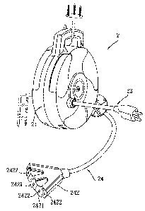
Referring to Figures 2 and 3, the preferred embodiment
of a wire rack assembly 2 according to the present
invention is shown to include: a casing 21 defining an
accommodating space 20 therein and provided with a
plurality of first conductive members 25 that are
disposed in the accommodating space 20; a first wire
231 connected to the first conductive members 25 and
provided with a plug 239 that is disposed outwardly of
the accommodating space 20; a reel 22 mounted rotatably
on the casing 21, defining a winding space 223, and
provided with a plurality of second conductive members
23 that are respectively in sliding contact with the
first conductive members 25; and a second wire 24 wound

CA 02610142 2007-11-09
4
on the reel 22 so as to be received in the winding space
223, connected to the second conductive members 23, and
provided withareceptacle242thatisdisposedoutwardly
of the winding space 223 and the accommodating space
20. The winding mechanism of the reel 22 is conducted
through a disc-shaped torsion spring (not shown) , which
iswell known in the art, and hence is not further detailed
herein.
The receptacle 242 is formed with a plurality of
plug-inserting units 2421, each of which is formed with
at least a pair of slots 2422 adapted for extension of
a pair of blades of an external plug (not shown)
thereinto.
The reel 22 has first and second wheels 222, 221 and
a hollow hub 224 that interconnects and that cooperates
with the first and second wheels 222,221 to define the
winding space 223 thereamong. The first wheel 222 has
a central wall 226 with inner and outer surfaces 2261,
2262 (see Figures 3 and 6) . Each of the second conductive
members 23 includes an annular plate 232 that is attached
to the outer surface 2262 of the central wall 226 of
the first wheel 222, and a connecting piece 234 extending
from the annular plate 232 through the central wall 26
and into the hub 224. The annular plates 232 of the second
conductive members 23 are disposed concentrically.
Referring to Figure 6, the second wire 24 extends
into the hub 224 to connect with the connecting pieces

CA 02610142 2007-11-09
234 of the second conductive members 23. In this
embodiment, the second wire 24 has three coupling ends
241, each of which is connected to a respective one of
the connecting pieces 234.
5 The reel 22 is further provided with three annular
confining members 233 (see Figure 3) that protrude from
and that are secured to the outer surface 2262 of the
central wall 226 of the first wheel 222 and that are
concentrically disposed to define a plurality of
concentrically disposed confining grooves 2330 (see
Figure 5) . Each of the annular plates 232 of the second
conductive members 23 is disposed in a respective one
of the confining grooves 2330.
Referring to Figure 4, in combination with Figures
3 and 5, the casing 21 is further provided with a
positioning seat 235 secured thereto, disposed in the
accommodating space 20, abutting against the annular
confining members 233, and formed with a plurality of
positioning holes 236 that are axially and respectively
aligned with the confining grooves 2330. Each of the
first conductive members 25 includes a spring-biased
terminal pins 237 that is urged by a spring 238, that
is connected to the first wire 231, and that extends
through a respective one of the positioning holes 236
to contact slidingly a respective one of the annular
plates 232 of the second conductive members 23.
In use, the wire rack assembly 2 is secured removably

CA 02610142 2007-11-09
6
to a wall provided with a power supply (not shown) , into
which the plug 239 can be plugged. The second wire 24
is then unwound from the reel 22, and the receptacle
242 is carried to the desired site where an external
plug (not shown) can be plugged thereinto. As compared
to the aforesaid conventional wire rack assembly, the
operation of the wire rack assembly 2 of this invention
is more convenient and the occurrence of a placement
problem due to an unsuitable site can be avoided.
While the present invention has been described in
connection with what is considered the most practical
and preferred embodiment, it is understood that this
invention is not limited to the disclosed embodiment
but is intended to cover various arrangements included
within the spirit and scope of the broadest
interpretation so as to encompass all such modifications
and equivalent arrangements.

Representative Drawing
A single figure which represents the drawing illustrating the invention.
Administrative Status

2024-08-01:As part of the Next Generation Patents (NGP) transition, the Canadian Patents Database (CPD) now contains a more detailed Event History, which replicates the Event Log of our new back-office solution.

Please note that "Inactive:" events refers to events no longer in use in our new back-office solution.

For a clearer understanding of the status of the application/patent presented on this page, the site Disclaimer , as well as the definitions for Patent , Event History , Maintenance Fee  and Payment History  should be consulted.

Event History

Description Date
Time Limit for Reversal Expired 2010-11-09
Application Not Reinstated by Deadline 2010-11-09
Deemed Abandoned - Failure to Respond to Maintenance Fee Notice 2009-11-09
Application Published (Open to Public Inspection) 2009-05-09
Inactive: Cover page published 2009-05-08
Inactive: IPC removed 2008-04-16
Inactive: IPC assigned 2008-04-16
Inactive: First IPC assigned 2008-04-16
Letter Sent 2007-12-14
Inactive: Filing certificate - RFE (English) 2007-12-14
Application Received - Regular National 2007-12-14
All Requirements for Examination Determined Compliant 2007-11-09
Request for Examination Requirements Determined Compliant 2007-11-09

Abandonment History

Abandonment Date Reason Reinstatement Date
2009-11-09

Fee History

Fee Type Anniversary Year Due Date Paid Date
Application fee - standard 2007-11-09
Request for examination - standard 2007-11-09
Owners on Record

Note: Records showing the ownership history in alphabetical order.

Current Owners on Record
CHI-WEN CHEN
Past Owners on Record
None
Past Owners that do not appear in the "Owners on Record" listing will appear in other documentation within the application.
Documents

To view selected files, please enter reCAPTCHA code :


To view images, click a link in the Document Description column. To download the documents, select one or more checkboxes in the first column and then click the "Download Selected in PDF format (Zip Archive)" or the "Download Selected as Single PDF" button.

List of published and non-published patent-specific documents on the CPD .

If you have any difficulty accessing content, you can call the Client Service Centre at 1-866-997-1936 or send them an e-mail at CIPO Client Service Centre.


Document
Description 
Date
(yyyy-mm-dd) 
Number of pages   Size of Image (KB) 
Claims 2007-11-08 3 73
Description 2007-11-08 6 186
Abstract 2007-11-08 1 19
Drawings 2007-11-08 6 132
Representative drawing 2009-04-15 1 8
Acknowledgement of Request for Examination 2007-12-13 1 176
Filing Certificate (English) 2007-12-13 1 159
Reminder of maintenance fee due 2009-07-12 1 110
Courtesy - Abandonment Letter (Maintenance Fee) 2010-01-03 1 174