Note: Descriptions are shown in the official language in which they were submitted.
CA 02610389 2014-04-23
AFS 209,222
LEADTHROUGH AND A SEALING ELEMENT
FOR THE LEADTHROUGH
CA 02610389 2007-11-09
AFS 209,222
BACKGROUND OF THE INVENTION
1. Field of the Invention
The present invention relates to a leadthrough for passing conduits such
as, e.g., tubular conduits, cables, or cable channels through constructional
components such as, e.g., ceilings and walls, and having a jacket tube, and
relates, in particular, to a sealing element of the leadthrough.
2. Description of the Prior Art
Leadthroughs of the type described above are installed during the
formation of a constructional component such as a wall or ceiling, or is
inserted
thereinto subsequently, after the wall or ceiling has been formed. In
particular,
the leadthrough can be cast into a concrete wall or a ceiling or,
alternatively,
subsequently, necessary openings are drilled, sawed, or cut. Preferably, such
leadthroughs are provided with a fire protection function. From the time of
installation or casting of the leadthrough in a constructional component and
installation of a conduit through the leadthrough, there already exists a need
in
fire protection. Further, it is important with such leadthroughs to insure
their
inner tightness against gaseous media, such as, e.g., a flue gas.
U.S. Patent Publication US 2004/0016190 discloses a device for passing
conduits and which includes a jacket tube and a base part connected with the
C:1Sym \Temp nolesC981213\ 209,222 pal appl Idthrnh 102607.DOC
CA 02610389 2007-11-09
jacket tube. The base part has a receiving space for firestop means and which
surrounds the through-opening. As the firestop means, an intumescent mass,
which expands in case of fire and closes the opening, is used. Between the
firestop means and a shoulder, an annular, a diaphragm-shaped sealing of an
elastomeric material is provided. The seal has an opening smaller than the
through-opening of the jacket tube.
The drawback of the known device consists in that the internal tightness
against gaseous media such as air or flue gas is very small and, therefore,
gastightness should be insured with additional measures which increase the
assembly costs and make the leadthrough more expensive.
Accordingly, an object of the present invention is to provide a sealing
element
for a leadthrough for passing conduits through constructional components and
which would provide an improved gastightness in the mounted condition of the
leadthrough, with a conduit passing therethrough.
SUMMARY OF THE INVENTION
This and other objects of the present invention ,which will become
apparent hereinafter, are achieved by providing a sealing element having a
flexible tubular body rotatable along a longitudinal axis of the tubular body
that
serves as a rotational axis, and a securing element provided on at least one
axial
C.VSKremp \ nokaC:98121% 209,222
pa i eppl Ixadihroup 102607 DOC
3
CA 02610389 2007-11-09
end of the tubular body with which the tubular body is secured in the jacket
tube
of the leadthrough.
The advantage of forming the sealing element as an elastic tubular body
consists in that the tubular body, because of its elasticity, can be twisted
around
its longitudinal axis, whereby the inner diameter of the tubular body becomes
reduced and the tubular body tightly surrounds the conduit that extends
through
the leadthrough. The contact between the tubular body and the conduits is
provided over a curtain length, which insures a very high tightness. Before
rotation of the tubular body, it has a large-cross-section that permits
passing of a
conduit through the tubular body, without damaging it.
Advantageously, the two axial ends of the tubular body rotate relatively
to each other generally by angle of at least 450, preferably, at least 900
.
Thereby, a very good tightness with respect to the conduit that extends
through
the tubular body, can be achieved. In order to insure gastightness of a
tubular
body through which no conduit extends, the two ends of the tubular body are
rotated relative to each other by an angle of at least 1800. The material,
which is
used for producing tubular bodies, is generally very thin and has preferably,
a
thickness .01 to 2 mm.
Advantageously, a further securing element is provided on the second
axial end of the tubular body. Thereby, the tubular member can be releasably
secured in the jacket tube at both of its ends.
C \Sys\ I cmpAnoleaC981211\ 209,222 pat appl IAUdihrough 102607 DOC
4
CA 02610389 2007-11-09
=
Advantageously, the securing element has at least one locking element
cooperating with a counter-locking element provided on a jacket tube of the
leadthrough. The locking element provides for an easy releasable connection of
the tubular body with the jacket tube.
Advantageously, the securing element is formed of several parts
containing a ring member connected with the tubular body for at least joint
rotation therewith, and a support member connectable with the ring member,
with the at least one locking member being arranged on the support member.
Advantageously, the tubular body is formed of gastight material such as,
e.g., cloth, rubbery material, or foil material, which material also has
elastic
properties.
It is advantageous when an elastic material such as, e.g., foamed or
rubbery material is provided on the inner side of the tubular body. The layer
of
the elastic material on the inner side of the tubular body further improves
tightness between the tubular body and a conduit extending therethrough.
Advantageously, the tubular body has in its middle region a waist-shaped
section. Thereby, a maximum possible reduction of the cross-section of the
opening can be achieved, so that with a conduit not yet extending through the
leadthrough, an open cross-section is not too large in an open condition.
The novel features of the present invention which are considered as
characteristic for the invention, are set forth in the appended claims. The
CA.V.11emp1nolesC981211 209,222 p.1 vppl 1_, id through 102607.00C
CA 02610389 2007-11-09
invention itself, however, both as to its construction and its mode of
operation,
together with additional advantages and objects thereof, will be best
understood
from the following detailed description of preferred embodiment, when read
with reference to the accompanying drawings.
BRIEF DESCRIPTION OF THE DRAWINGS:
The drawings show:
Fig. 1 a perspective view of a leadthrough according to the present
invention and including a jacket tube and sealing element;
Fig. 2 a detail view of a section of the leadthrough shown in Fig. 1;
Fig. 3 a cross-sectional view of the leadthrough shown in Fig. 1 in a
mounted condition in a constructional component; and
Fig. 4 a side view of the leadthrough shown in Fig. 3 with an inserted
conduit and a closed sealing element.
DETAILED DESCRIPTION OF
THE PREFERRED EMBODIMENTS
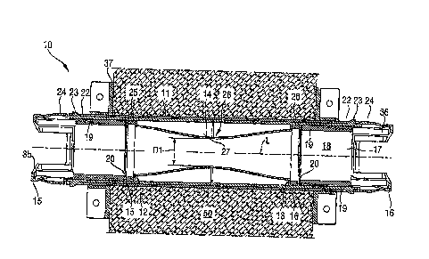
A leadthrough 10 according to the present invention, which is designed
for insertion in a constructional component 50 (see Figs. 3-4), e.g., a
concrete
wall and which is shown in Figs. 1-4, has a jacket tube 11 that is formed of
two
C ktiyAremp nolesC9812FA209,222 pat appl lAmdtbrough 102607 DOC
6
CA 02610389 2007-11-09
parts and is shown in Fig. 1 in an open condition for a better clarity. The
leadthrough 10 further includes a sealing element that is formed as a tubular
body 14 rotatable about its longitudinal axis that serves as a rotational
axis. At
the opposite first and second ends 12, 13 of the tubular body 14, there are
arranged, respectively, first and second ring members 25, 26 that serve as
support members for the tubular body 14. The tubular body 14 is formed of,
e.g., flexible and/or elastic, thin-walled, and gastight rubbery, cloth, or
foil
material and is provided on its inner side with an elastic material 27 such
as,
e.g., foamed material or rubbery material (see Fig. 3). "Thin-walled"
signifies
that the thickness of the material amounts to about .01 ¨ 2 mm.
The elastic material 27 can be provided, e.g., in form of a continuous
layer on the inner side of the tubular body 14 or, e.g., be applied
regionwise,
e.g., in form of strips or ribs extending in the longitudinal direction of the
tubular body 14. The tubular body 14 an have a waist-like portion 28 that
would have, in a mounted condition in the jacket tube 14 of the leadthrough
10,
an inner diameter D1 smaller than the maximal diameter of the tubular body 14.
The inner diameter defines a cross-sectional width of the opening of the
tubular
member 14 (so that the tubular bodies have an oval or polygonal cross-section
and not a circular cross-section). The tubular body 14 is rotatable at its
axial
ends 12, 13 in opposite directions generally by at least 45 , preferably by at
least
90 , so that the inner diameter of the tubular body 14 can be maximum reduced
CASyMTemp1ool.C9812131209,222 pal nppl Loa dilanugh 102607.1XX
7
CA 02610389 2007-11-09
to zero value. Between the two ring members 25, 26 and/or between the two
axial ends 12, 13 of the tubular body and jacket tube 11, in order to improve
the
gastightness, a seal can be provided.
The ring members 25, 26 form, together with a two-part first and second
support member 35, 36, respectively, securing elements 15, 16 with which the
tubular body 14 is secured in the jacket tube 11, with the tubular body 14
extending along the longitudinal extension of the jacket tube 11. The tubular
body 14 have advantageously an axial length that corresponds at least to 1.5
times of its smallest diameter or, at not round tubular bodies, its smallest
extent
transverse to its longitudinal axis. The support members 35, 36 are formed, in
the present case, regionwise as sleeve-shaped members and completely
surround the tubular body 14. The support members 35, 36 have each a
connection section 20 with which they are connected with the tubular body 14
or with the ring members 25, 26 which are connected with the tubular body 14
for joint rotation therewith. In the embodiment shown in the drawings, the
ring
members 25, 26 are clampingly secured on the connection sections 20. The
support members 35, 36 further have each a receiving cavity 18 for a firestop
means 19 and which surrounds the through-opening 17 (see Figs. 1-3) which is
provided on a side of the support member 35, 36 remote from the tubular body
14. The firestop means 19 is formed, e.g., as a ring of intumescent material
and
insures the fire protection of the leadthrough. In addition, in the interior
of the
CASys \Temp \ stotesC:981213\ 209,222 pal appl Icadthrough 102607.DOC
8
CA 02610389 2007-11-09
jacket tube 11, e.g., in the middle between the ends of the jacket tube 11, an
additional firestop element (not shown here), e.g., in form of a ring of an
intumescent material can be provided. As particularly shown in Fig. 2, each
securing element 15, 16 has at least one locking element 23 lockingly
engageable with a counter-locking element 22 provided on the jacket tube 11,
in
order to releasably secure a unit which is formed of the tubular body 14 and
securing elements 15, 16, on the jacket tube 11.
In the embodiment of the invention shown in the drawings, the locking
element 23 is formed, on each of the securing elements 15, 16, as a locking
hook. The locking elements 23 are operated by an operational element 24.
In Fig. 1, the tubular member 14 is located in the jacket tube 11 together
with the two securing elements 15, 16. The ring members 25, 26 are secured in
the respective connection sections 20 of the support members 35, 36. The
locking element 23 engages in the counter-locking element 22 provided on the
jacket tube 11 (see also Fig. 2).
Figs. 3-4 show an arrangement of the inventive leadthrough 10 in
constructional component 50. The leadthrough 10 can be inserted in an opening
in the constructional component 50 or be embedded there during the formation
of the constructional component, e.g., a concrete wall. For preventing action
of
tensioning or thrust forces on the leadthrough 10, the leadthrough has, on
both
side of the constructional component 50, mounting elements 37 such as, e.g.,
C ktiyxµTemp \ noaNC9812B1209,222 pal appl Leadthrough 1026417 DOC
9
CA 02610389 2007-11-09
mounting flanges which have openings 38 for passing fastenings elements such
as, e.g., screws or nails. The cross-section or the diameter D1 in the region
of
the waist-like section 28 of the tubular body 14 is so selected that conduits
40
such as cable, tube, etc. shown in Fig 4, can be inserted therethrough,
without
damaging the tubular body 14.
After a conduit 40 has passed through the opening 17 of the
leadthrough10, one of the securing elements 15, 16 can be released with
respect
to the jacket tube 11 by manually lifting the locking elements 23 off the
counter-locking elements 22 with the operational element 24. Finally, a
securing element 15, 16 can be rotated relative to the jacket tube 11, e.g.,
in
direction of arrow 30 in Fig. 4. This results in rotation of the tubular body
14
the cross-section of which is so reduced that it tightly surrounds the conduit
40,
as shown in Fig. 4. The tubular body 14 has only an inner diameter that
corresponds to the diameter D2 of the conduit 40. In this rotated or pivot
position, the locking elements 23 can again fall in the counter-locking
elements
22, after the operational element 24 is not operated any more by the user, so
that
the tubular body 14 becomes secured in its rotated or pivot positions. To open
the tubular body 14 again, the above-described procedure should be repeated in
an opposite rotational direction.
Though the present invention was shown and described with references to
the preferred embodiments, such are merely illustrative of the present
invention
CASys \ Temp \milesC98121A 209,222 pal dppl 1,edihrough 102607.DOC
CA 02610389 2014-06-13
and are not to be construed as a limitation thereof and various modifications
of the present invention will be apparent to those skilled in the art.
11
11798477.1