Language selection

Search

Patent 2610729 Summary

Third-party information liability

Some of the information on this Web page has been provided by external sources. The Government of Canada is not responsible for the accuracy, reliability or currency of the information supplied by external sources. Users wishing to rely upon this information should consult directly with the source of the information. Content provided by external sources is not subject to official languages, privacy and accessibility requirements.

Claims and Abstract availability

Any discrepancies in the text and image of the Claims and Abstract are due to differing posting times. Text of the Claims and Abstract are posted:

  • At the time the application is open to public inspection;
  • At the time of issue of the patent (grant).
(12) Patent Application: (11) CA 2610729
(54) English Title: THERMOCYCLER
(54) French Title: THERMOCYCLEUR
Status: Dead
Bibliographic Data
(51) International Patent Classification (IPC):
  • B01L 7/00 (2006.01)
(72) Inventors :
  • TASCH, HENNER (Germany)
  • KRUGER, BERND (Germany)
(73) Owners :
  • EPPENDORF AG (Germany)
(71) Applicants :
  • EPPENDORF AG (Germany)
(74) Agent: PERLEY-ROBERTSON, HILL & MCDOUGALL LLP
(74) Associate agent:
(45) Issued:
(86) PCT Filing Date: 2006-03-04
(87) Open to Public Inspection: 2006-12-21
Availability of licence: N/A
(25) Language of filing: English

Patent Cooperation Treaty (PCT): Yes
(86) PCT Filing Number: PCT/EP2006/001995
(87) International Publication Number: WO2006/133749
(85) National Entry: 2007-12-03

(30) Application Priority Data:
Application No. Country/Territory Date
10 2005 027 555.9 Germany 2005-06-14

Abstracts

English Abstract


Thermocycler having a base body, which has a temperature-controllable
receiving region for reaction vessels, and having a lid which can be mounted
on the base body and can be brought, in the mounted state, from an open
position into a working position over the receiving region, wherein an optics
unit is arranged in the lid, wherein optics unit and/or receiving region are
received in the lid or base body with play, wherein the play permits a
relative movement sufficient for adjustment of the optics unit with respect to
the receiving region between optics unit and receiving region, and in each
case at least 2 positioning directions are provided on the base body and lid,
which permit a reproducible alignment of optics unit and receiving region in a
mutually adjusted position.


French Abstract

L'invention concerne un thermocycleur qui comprend un élément de base pourvu d'une zone de réception pouvant être tempérée pour des réacteurs et un couvercle, qui peut être placé sur l'élément de base et qui, étant monté, peut passer d'une position ouverte à une position de travail par l'intermédiaire de la zone de réception. Le couvercle est équipé d'une unité optique, cette unité optique et/ou la zone de réception étant logées avec un certain jeu dans le couvercle ou l'élément de base. Ce jeu permet un mouvement relatif suffisant entre l'unité optique et la zone de réception pour ajuster l'unité optique par rapport à la zone de réception. L'élément de base et le couvercle comprennent au moins deux dispositifs de positionnement qui permettent de reproduire l'orientation de l'unité optique par rapport à la zone de réception en une position d'ajustement mutuelle.

Claims

Note: Claims are shown in the official language in which they were submitted.


9


CLAIMS


1. A thermocycler, comprising a base fitted with a temperature-controlled
receiving segment of reaction vials, and further comprising a top which can be

mounted on the base and which in its assembled state can be displaced from an
open position wherein the receiving segment is accessible for purposes
inserting
and removing the reaction vials, into an operational position above the
receiving
segment, an optics being configured In the top and in its operational position

radiating light into the reaction vials and/or detecting light issuing from
the reaction
vessels,

characterized
in that the optics (17) and/or the receiving segment (13) are received with
play in the
top (12) respectively the base (11), the play allowing relative movement
between the
optics (17) and the receiving segment (13) sufficient for adjustment of the
optics
(17) and the receiving segment (13) and in that at least 2 positioning
elements (15,
16; 27, 28) are present both in,the base (11) and in the top (12), each
positioning
element (27, 28) at the top (12) being associated with a positioning element
(15,16)
at the base (11) and in that at least one of these two mutually associated

positioning elements (27, 28) is adjustable in position relative to the
receiving
segment (13) or to the optics (17) and is affixable in a set position to be
stationary
relative to the receiving segment (13) and/or the optics (17) in a manner that


10


adjusting the optics (17) relative to the receiving segment (13) allows
mutually
aligning the associated positioning elements (15, 27; 16,28) into permanent
affixation.


2. Thermocycler as claimed in claim 1, characterized in that only the
optics (17) is received with play in the top (12).


3. Thermocycler as claimed in either of claims 1 and 2, characterized in
that when the top is moved into its operational position (12), the positioning

elements (15, 16; 27, 28) automatically align the receiving segment (13) and
the
optics (17) into their adjusted position.


4. Thermocycler as claimed in claim 3, characterized in that the mutually
associated positioning elements (15, 27; 16, 28) are bushes and pins that
engage
each other in mutually interlocking manner.


5. Thermocycler as claimed in either of claims 3 and 4, characterized in
that only the positioning elements (27, 28) configured at the top (12) can be
adjusted
in position.


11


6. Thermocycler as claimed in one of the above claims, characterized in

that the optics (17) comprises elements (22) allowing adjusting it relative to
the
receiving segment (13) by means of a gauge (23) mounted on said segment.


Description

Note: Descriptions are shown in the official language in which they were submitted.


CA 02610729 2007-12-03

THERMOCYCLER
The present invention relates to a thermocycler defined in the preamble of
claim 1.

The term uthermocycler" in general denotes apparatus carrying out
PCR(eactions). The abbreviation PCR is known to the expert as a method using
polymerase allowing amplifying target nucleic acids contained in a test
sample.

The present invention relates to thermocyclers allowing measuring in real time
and over time the increase in the amplified products. Such thermocyclers
comprise
a base fitted with a temperature-controlled receiving segment receiving
reaction vials
suitable to carry out the PCR.

Such apparatus moreover is fitted with a top displaceable from an open
position into an operational one above the receiving segment. The top contains
an
optics which in its operational position is opposite the receiving segment and
acts
as a transceiver radiating light into the reaction vials and receiving the
light issuing
from them.

As a rule fluorescent substances are contained in real-time PCR batches, the
optics transmitting exciting light into the reaction vessels and detecting any
emitted
fluorescence.

In general several light paths are designed into the optics, each light path
being allocated to a particular reaction vial seat in the receiving segment.
To


CA 02610729 2007-12-03
2

assure error-free measurement, the optics and the receiving segment must be
accurately aligned to each other during PCR.

Most cases preclude factory adjustment. Illustratively, on account of weight,
the top and the base are generally shipped separately. Also, the base is not
necessarily restricted to real time procedures, but also may be used with
other tops
for conventional PCR

Accordingly, in many applications, the top shall be mounted only
subsequentty on the base, namely after both units have left the factory.

The objective of the present invention is to create a thermocycler allowing in
especially simple manner lasting/permanent adjustment between the optics and
the
receiving segment also when they are assembled subsequently.

This problem is solved by apparatus defined by the features of claim 1.

In the themnocycler of the present invention, the optics and/or the receiving
segment are seated with play in the top respectively the base. This play must
be
selected in a manner to allow adequate relative displacement between the
optics
and the receiving segment to adjust these relative to each other.

Moreover the base and the top each are fitted with at least 2 positioning
elements, each positioning element at the base being associated with one
positioning element at the top. At least one of these two mutually associated
elements is adjustable in position relative to the receiving segment or the
optics and


CA 02610729 2007-12-03
3

once in its adjusted position can be affixed in place relative to the said
receiving
segment and/or optics.

One substantive effect of the present invention is that the receiving segment
and/or the optics are mounted with play in the base respectively to the top,
which is
the sine qua non condition allowing adjustment for instance following or
during top
assembly. As elucidated farther below, the adjustment may be implemented by
means of a gauge deposited on the receiving segment and aligning the optics
when
the top is lowered into 'rts operational position.

Said posftioning elements are used to allow repeated(ly)? arrangement of
optics and receiving segment in the aligned position without readjustment
during
operation of the thermocycler.

During adjustment, the positioning elements of the thermocycler of the
present invenfJon are aligned relative to each other and affixed in their set
position,
that is, when they are received in displaceable manner. Following their
affixation, all
positioning elements are stationary in their positions relative to the
receiving
segment respectively the optics. For operation, it suffices to mutually align
the
positioning elements, as a result of which the optics and the receiving
segment shall
be automatically adjusted relative to one another.

Advantageous embodiment modes of the present invention are defined in the
dependent claims.


CA 02610729 2007-12-03
4

In operation, the above discussed adjustment takes place in real time. In
order not to design the base -- which is not inevitably operated in real time -
in
unnecessarily complex manner, the elements required for adjustment are fitted
merely into the top. In a preferred embodiment of the present invention, only
the
optics shall be received with play in the top, the receiving segment being
seated in
fixed manner in the base,

Conceivably there shall be a series of different, appropriate posifioning
elements. Illustrativefy such positioning elements may be merely detectable
marks
which, once the top is in the operational position, only need be mutually
centered.
Also illustratively, LED's might be used as the positioning elements while
associated
perforated templates are configured in the top. In that case a detector system
might
measure the light intensity passing through the said perforations and the
adjusted
position might be set for instance by displacing the optics until a maximum
light
intensity has been detected. Also magnetic or electric positioning elements
might
be used among many such approaches.

Preferably however such positioning elements shall be used that, when the
top is moved into its operational position, will mechanically engage said top
and
thereby mutually align the receiving segment and the optics Into their
mutually
adjusted position.


CA 02610729 2007-12-03

In this regard, an especially preferred embodiment of the present invention
employs for instance guide pins acting as said guide elements illustratively
configured at the base and engaging bushes configured at the top in
geometrically
locking manner.

As already mentioned above, the base may also be used for other than real
time purposes; illustratively -- instead of the optics being received in the
top with
play while the receiving segment is configured firmly affixed in the base -
only the
positioning elements fitted on the top area may be adjustable and affixable in
their
distance from the optics, whereas the positioning elements at the base cannot
be
adjusted, that is they are permanently affixed in place.

Furthermore and as already mentioned above, preferably a gauge is used
during assembly when adjusting the optics and the receiving segment. This
gauge
illustratively is mounted in defined manner on the receiving segment and for
instance
is fitted upward pointing guide edges that shall engage associated mating
walls at
the lower optics end which they then shall commensurateiy displace into its
adjusted
position.

The present invention is elucidated below in relation two Figures.

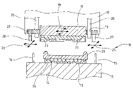
Fig. I diagrammatically shows a sectional front view of the thermocycler of
the present invention, the optics being shown in section along line 1-1 of
Fig. 2, and
Fig. 2 is a top view of the optics of the thermocycler of the present
invention.


CA 02610729 2007-12-03
6

Fig. 1 shows a thermocycler 10 comprising a base 11 and a top 12. The base
11 is fitted with a temperature-controlled receiving segment 13 fitted with
reaction
viaE wells 14.

Positioning elements in the form of pins 15 and 16 are mounted on the base
11. The positioning elements 15 and 16 are stationary and are spaced away from
the receiving segment 13 which also is stationary,

An optics 17 is supported with play in the direction of the arrow 18 in the
top
12 by means of boreholes 19 receiving retention bars 20. The diameter of the
boreholes 19 slightly exceeds that of the bars , subtending thereby said play.

Measuring apertures 21 are configured at the lower end of the optics 17.
Also, said lower end is fitted with a frame 22. The frame 22 is shaped in a
manner
that it can engage in adjusting manner a gauge 23 which, in the embodiment
shown,
can be deposited in predetermined manner, by means of studs 24, on the
receiving
segment 13.

As the top 12 is lowered, the frame 22 will engage the gauge 23 and thereby
will displace the optics 17, in this case to the right, as a result of which
the optics 17,
that is its measuring apertures 21, shall then be adjusted for proper
alignment with
the reaction vial wells 14.


CA 02610729 2007-12-03
7

Furthermore positioning elements designed as bushes 27 and 28
displaceable in grooves 29, 30 in the direction of the arrows 25 and 26 are
configured in the top.

During the alignment of the optics 17 with the receiving segment 13, the
bushes 27 and 28 are moved to geometrically intetiock with the pins 15 and 16;
this
feature is easily assured by the displaceability of said bushes.

As soon as the optics unit 17 is adjusted by the gauge 23 relative to the
receiving segment 13 and once the pins 15 and 16 have trapped the bushes 27
and
28, the latter can be affixed by omitted elements such as screws etc. into
their
particular positions. Thereupon the bushes 27 and 28 no longer are
displaceable in
the directions of the arrows 25 and 26. Instead they are stationary relative
to the
optics 17 and can only be moved jointly with said optics in the direction of
the arrow
18.

Accordingly the adjusted position of the optics 17 determined by the gauge 23
is reproducible at every descent in that the pins 15 and 16 engage the bushes
27
and 28.

For a better understanding reference is made to Fig. 2, showing a top view of
the optics 17 of Fig. 1.

Accordingly, the optics 17 is supported by means of four boreholes 19 at
retaining bars 20 w'rth play in the direction of the arrow 18. The bushes 27
and 28


CA 02610729 2007-12-03
8

are adjustable In grooves 29, 30 in the directions of the arrows 26 and 25 and
can
be affixed In a set positifln by an omitted element.

Representative Drawing
A single figure which represents the drawing illustrating the invention.
Administrative Status

For a clearer understanding of the status of the application/patent presented on this page, the site Disclaimer , as well as the definitions for Patent , Administrative Status , Maintenance Fee  and Payment History  should be consulted.

Administrative Status

Title Date
Forecasted Issue Date Unavailable
(86) PCT Filing Date 2006-03-04
(87) PCT Publication Date 2006-12-21
(85) National Entry 2007-12-03
Dead Application 2012-03-05

Abandonment History

Abandonment Date Reason Reinstatement Date
2011-03-04 FAILURE TO REQUEST EXAMINATION
2011-03-04 FAILURE TO PAY APPLICATION MAINTENANCE FEE

Payment History

Fee Type Anniversary Year Due Date Amount Paid Paid Date
Application Fee $400.00 2007-12-03
Registration of a document - section 124 $100.00 2007-12-13
Maintenance Fee - Application - New Act 2 2008-03-04 $100.00 2008-02-15
Maintenance Fee - Application - New Act 3 2009-03-04 $100.00 2009-02-09
Maintenance Fee - Application - New Act 4 2010-03-04 $100.00 2009-12-29
Owners on Record

Note: Records showing the ownership history in alphabetical order.

Current Owners on Record
EPPENDORF AG
Past Owners on Record
KRUGER, BERND
TASCH, HENNER
Past Owners that do not appear in the "Owners on Record" listing will appear in other documentation within the application.
Documents

To view selected files, please enter reCAPTCHA code :


To view images, click a link in the Document Description column. To download the documents, select one or more checkboxes in the first column and then click the "Download Selected in PDF format (Zip Archive)" or the "Download Selected as Single PDF" button.

List of published and non-published patent-specific documents on the CPD .

If you have any difficulty accessing content, you can call the Client Service Centre at 1-866-997-1936 or send them an e-mail at CIPO Client Service Centre.


Document
Description 
Date
(yyyy-mm-dd) 
Number of pages   Size of Image (KB) 
Abstract 2007-12-03 2 92
Claims 2007-12-03 3 58
Drawings 2007-12-03 2 33
Description 2007-12-03 8 215
Representative Drawing 2008-02-22 1 14
Cover Page 2008-02-25 1 47
PCT 2007-12-03 3 95
Assignment 2007-12-03 5 137
Assignment 2007-12-13 2 67
Fees 2008-02-15 1 27
Fees 2009-02-09 1 200
Fees 2009-12-29 1 200