Note: Descriptions are shown in the official language in which they were submitted.
CA 02611476 2009-11-20
1
Description
DENTAL PROSTHESIS AND ITS MANUFACTURING METHOD
Technical Field
[11 The present invention relates to a dental prosthesis and its manufacturing
method for
restoring a lost tooth, and more particularly, to a dental prosthesis which
has a male
member formed on a holding part attached on an adjacent tooth for attaching an
artificial
tooth on the adjacent tooth and a female member formed in the artificial tooth
so that the
artificial tooth and the adjacent tooth can be connected with each other
without grinding
of the adjacent tooth, and a method for manufacturing the dental prosthesis
which
includes the steps of duplicating an original model, waxing up the duplicated
model,
holding a sprue on the duplicated model in a state where the duplicated model
is waxed
up, and investing, burning out and casting the duplicated model.
[2]
Background Art
[3] In general, to restore a lost tooth, an adjacent tooth located by the side
of an artificial
tooth to be restored is ground, and a crown made of metal or ceramic material
is covered
on the ground adjacent tooth and connected and fixed to the artificial tooth.
[4] For a representative example of the conventionally dental prosthesis,
there is a crown
bridge. In the case of the conventional crown bridge, adjacent teeth I a
located at both
sides of an artificial tooth to be restored are ground from the dotted line to
the solid line
shown in FIG. 1, and the artificial tooth 2 shown in FIG. 2 is connected to a
crown 2a
formed on an abutment and fixed at the ground portion.
[5] However, the conventional crown bridge has several disadvantages in that
it causes
degeneration or exposure of dental pulp, or hypersensitivity since a loss of
tooth
substance is increased, and in that it is impossible to restore the original
occlusal form
due to the grinding of the occlusal surface of the adjacent teeth. Moreover,
occasionally,
it is necessary to previously carry out endodontic treatment since an amount
of tooth
grinding is increased during restoration of a severely inclined tooth.
[6] Alternatively, there is an implant as the dental prosthesis. The implant
prosthesis is a
method for fixing an artificial tooth using a screw after implanting a metal
artificial root.
However, the implant has several disadvantages in that it takes much time and
money to
fix the artificial tooth, has limitations in restoration in the case of
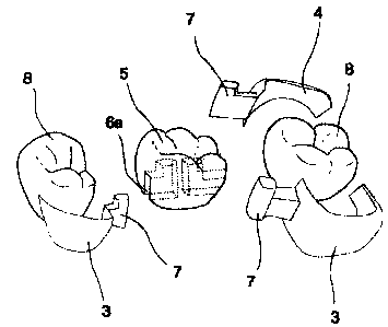
patients of severe
CA 02611476 2009-11-20
2
periodontal disease, wasting diseases, diabetes and hematologic diseases, and
is
relatively weak to lateral pressure.
[7] Therefore, development of a dental prosthesis which is easy to operate and
can fix the
artificial tooth without grinding of adjacent teeth has been required. In the
prior art
prostheses, it is difficult to apply various prostheses according to
conditions of adjacent
teeth, since it is unavoidable to form holes in the adjacent teeth or grind
the adjacent
teeth to hold the fixed state of the prostheses.
[8] Meanwhile, a method for manufacturing the conventional dental prosthesis
includes
the steps of waxing up an original model of the prosthesis, removing the waxed-
up model
from the original model, investing and casting the waxed-up model after
holding a sprue
on the waxed-up model, and mounting it to the original model. However, such
conventional method has a disadvantage in that it is difficult to obtain
holding force to
the maximum.
[9]
Disclosure of Invention
Technical Solution
[10] Accordingly, it is an object of the present invention to provide a dental
prosthesis and
its manufacturing method, which can fix a holding part to an adjacent tooth
with no or
little grinding of the adjacent tooth, thereby easily and firmly fixing an
artificial tooth to
the holding part attached on the adjacent tooth and providing natural and
various outward
appearances according to tooth conditions.
Li 1] To achieve the above object, the present invention provides a dental
prosthesis which
has a male member formed on a holding part attached on an adjacent tooth for
attaching
an artificial tooth on the adjacent tooth and a female member formed in the
artificial
tooth so that the artificial tooth and the adjacent tooth can be connected
with each other
without grinding of the adjacent tooth, and a method for manufacturing the
dental
prosthesis which includes the steps of duplicating an original model, waxing
up the
duplicated model, holding a sprue on the duplicated model in a state where the
duplicated
model is waxed up, and investing, burning out and casting the duplicated
model.
[11A] According to an embodiment of the present disclosure there is provided a
dental
prosthesis which includes holding parts for fixing an adjacent tooth, a male
member
formed integrally with the holding parts, a female member formed integrally
with an
artificial tooth and having a slot to insert the male member thereto to
thereby recover or
CA 02611476 2009-11-20
2a
promote a function of a damaged tooth, wherein the holding parts cover a part
or the
whole of the adjacent tooth to surround the adjacent tooth the holding parts
are modeled
on the original surface pattern of the adjacent tooth to provide the same
surface pattern as
the adjacent tooth whereby the holding parts can be fixed to the adjacent
tooth with no or
little grinding of the adjacent tooth.
[12]
Advantageous Effects
[13] The present invention which has no anesthesia and grinding of teeth can
promote
dental health since a patient can go to a dental clinic in a good feeling
without fear to
dental care losing no time of restoration, and restore teeth even in the case
of patients,
who have hypertension or angina pectoris patient or are warned to anesthesia,
restricted
in restorations.
[14] The dental prosthesis according to the present invention does not cause
oversensitive
reaction and require endodontic treatment after the tooth restoration since it
restores the
tooth with no grinding of the tooth and no influence on the dental pulp, and
3
WO 2006/132464 PCT/KR2006/000477
can prevent decay of teeth since it conserves enamel, which is the hardest in
a human
body. Furthermore, the dental prosthesis according to the present invention
can keep
the present occlusion state since the occlusal surface is not ground, and does
not
provide the patient with a sense of foreign substance since the opposite tooth
is not
changed and the contact point with the opposite tooth is kept as it is. In
addition, the
dental prosthesis does not cause a damage of soft tissue, which may be caused
during
grinding of the tooth, and prevents decay of teeth by melting of cement due to
improper grinding of the tooth.
[15] Moreover, the dental prosthesis according to the present invention can
remarkably
reduce medical accidents since there is no cross infection between patients
due to
improper disinfection in a dental clinic, does not need anesthesia agent and
tooth
grinding agent, remarkably reduces medical consultation hours, and can be
easily
removed when the dental prosthesis has to be unavoidably removed. Therefore,
the
dental prosthesis according to the present invention is the most human-
friendly.
[16]
Brief Description of the Drawings
[17] FIG. 1 is a side view showing a grinding portion in the case where a
conventional
dental prosthesis is applied;
[18] FIG. 2 is a side view showing a mounted state of the conventional dental
prosthesis;
[19] FIG. 3 is an exploded perspective view of a dental prosthesis according
to the
present invention;
[20] FIG. 4 is an enlarged view of a lingual side of FIG. 3;
[21] FIG. 5 is an enlarged view of a lingual side of male members formed at
both ends
of a holding part of the dental prosthesis according to the present invention;
[22] FIG. 6 is a perspective view and a plan view showing a state where an S-
shaped
holding part is mounted on adjacent teeth according to the present invention;
[23] FIG. 7 is a perspective view of an integrated type holding part of the
present
invention;
[24] FIG. 8 is a perspective view of a separated type holding part of the
present
invention;
[25] FIG. 9 is a perspective view showing a coupling part formed at the rear
part of the
holding parting FIG. 8;
[26] FIG. 10 is a perspective view showing coverage of the pit, the non-
functional cusp
and a portion of the occlusal surface;
[27] FIG. 11 is a perspective view of a modification of the holding part of
FIG. 7;
[28] FIG. 12 is a plan view of the separated type holding part and the male
member of
FIG. 8;
CA 02611476 2007-12-07
4
WO 2006/132464 PCT/KR2006/000477
[29] FIG. 13 is a plan view of the integrated type holding part and the male
member;
[30] FIG. 14 is a side view of the holding parts of FIGS. 7 and 8 seen from
the buccal
side;
[31] FIG. 15 is a side sectional view, in a partial section, showing a mounted
state of the
dental prosthesis according to the present invention;
[32] FIG. 16 is a front view, in a partial section, showing an angle of the
male member
of the dental prosthesis according to the present invention;
[33] FIG. 17 is a sectional view showing a state where the male member of the
holding
part is coupled to an artificial tooth of the dental prosthesis according to
the present
invention;
[34] FIG. 18 is a side view showing a mounted state of the prosthesis
according to the
present invention;
[35] FIG. 19 is a perspective view of an embedded type holding part according
to the
present invention;
[36] FIG. 20 is a perspective view of the embedded type holding part according
to the
present invention;
[37] FIG. 21 is a perspective view of the embedded type holding part according
to the
present invention;
[38] FIG. 22 is a perspective view of the embedded type holding part according
to the
present invention;
[39] FIG. 23 is a perspective view showing a state where an embedded part is
added to
FIG. 19;
[40] FIG. 24 is a perspective view showing a modification of the holding part
of FIG.
19;
[41] FIG. 25 is a front view and a perspective view showing an indented
portion of a
scratch type;
[42] FIG. 26 is a front view and a perspective view showing an indented
portion of a dot
type;
[43] FIG. 27 is a front view and a perspective view showing an indented
portion of a
hole type;
[44] FIG. 28 is a front view and a perspective view showing an indented
portion of a box
type;
[45] FIG. 29 is a front view showing a grinding portion on a lingual side of
the anterior
tooth;
[46] FIG. 30 is a front view showing another grinding portion on the lingual
side of the
anterior tooth;
[47] FIG. 31 is a perspective view showing the embedment at the rear of an
embedded
type holding part;
CA 02611476 2007-12-07
5
WO 2006/132464 PCT/KR2006/000477
[48] FIG. 32 is a perspective view showing another embedment at the rear of
the
embedded type holding part;
[49] FIG. 33 is a plan view of the embedded type holding part and a male
member;
[50] FIG. 34 is a side view of the holding parts seen from the buccal side;
[51] FIG. 35 is a side sectional view, in a partial section, showing a mounted
state of the
dental prosthesis according to the present invention;
[52] FIG. 36 is a front view, in a partial section, showing an angle of the
male member
of the dental prosthesis according to the present invention; and
[53] FIG. 37 is a sectional view showing a state where the male member of the
holding
part is coupled to an artificial tooth of the dental prosthesis according to
the present
invention
[54]
Best Mode for Carrying Out the Invention
[55] Reference will now be made in detail to the preferred embodiments of the
present
invention, examples of which are illustrated in the accompanying drawings.
[56] FIGS. 3 to 17 are views showing a dental prosthesis according to a
preferred
embodiment of the present invention.
[57] As shown in FIGS. 3 and 4, the dental prosthesis according to the present
invention
includes: an artificial tooth 5 having female members 6 and slots 6a; and
holding parts
3 and 4 respectively having male members 7 formed integrally with the holding
parts 3
and 4 and inserted into the female members 6 and the slots 6a of the
artificial tooth 5,
and fixed to an adjacent tooth 8.
[58] Combining force between the holding parts 3 and 4 and the adjacent tooth
8 is
increased by maximizing an area of the holding parts 3 and 4, and combining
force
between the holding parts 3 and 4 and the artificial tooth 5 is increased by
maximizing
an area of the female member 6 and the male member 7. At this time, sizes of
the
female member 6 and the male member 7 are adjustable according to
circumstances.
[59] Meanwhile, the male member 7 and the holding parts 3 and 4 are formed
integrally
with each other as shown in FIG. 7, or divided into a lingual side and a
buccal side as
shown in FIG. 8.
[60] Furthermore, in the case where the male member 7 and the holding parts 3
and 4 are
divided into the lingual side and the buccal side and there is no tooth at the
back of the
holding parts 3 and 4, as shown in FIG. 9, a pair of projection 9a and groove
9b are
formed at the ends of the lingual holding part 3 and the buccal holding part 4
and
coupled with each other in order to increase combining force between the
holding parts
3 and 4.
[61] After that, in case of the adjacent tooth 8 whose holding parts 3 and 4
may be
CA 02611476 2007-12-07
6
WO 2006/132464 PCT/KR2006/000477
exposed to the outside, as shown in FIGS. 12 and 13(3), on the anterior tooth
and a
portion which requires an aesthetic sense, only the lingual holding part 3 is
formed, but
on the posterior tooth as shown in FIG. 4, the lingual holding part 3 and the
buccal
holding part 4 may be formed separately as shown in FIG. 8 or integrally as
shown in
FIG. 7. Alternatively, the prosthesis can be formed in an S shape (FIG. 6) in
such a
way that only the lingual holding part 3 is mounted on the anterior tooth and
the front
portion of the artificial tooth and only the buccal holding part 4 is mounted
on a molar
tooth and the posterior tooth of the artificial tooth. In the prosthesis
having the above
structure, the holding part is not exposed to the outside since only the
lingual holding
part 3 is mounted on the anterior tooth and the portion, which requires the
aesthetic
sense.
[62] Meanwhile, as shown in FIG. 10, the holding parts 3 and 4 are
manufactured in
such a way that the pit, the non-functional cusp and the entire or a part of
the occlusal
surface, which is not in contact with the opposite tooth, are covered.
Furthermore, the
lingual holding part 3 mounted on the anterior tooth and the portion which
requires the
aesthetic sense covers the lingual side to the maximum within a range not
causing any
obstacle to occlusion, whereby the prosthesis can endure lateral pressure and
vertical
pressure.
[63] Moreover, the male member 7 may be formed in one of T, I, L and 0 shapes
and
other various shapes in order to maximize holding force between the female
member 6
and the male member 7. Shape of the female member 6 and the slot 6a is
determined
according to the shape of the male member 7.
[64] Additionally, as shown in FIG. 5, in the case where there is any missing
tooth at the
right or left of the adjacent tooth, since the prosthesis can be manufactured
in such a
way that the male member 7 is formed at the right or left of the holding part,
it can
prosthetically treat the missing tooth in any cases with no grinding.
[65] The male member 7 having the above structure serves to keep parallel
between the
missing adjacent teeth together with the holding part, so as to lead a smooth
insertion
of the artificial tooth 5 and reinforce compression resistance.
[66] Therefore, the prosthesis according to the present invention can endure
vertical
pressure and horizontal pressure using elasticity of metal of the prosthesis
used for
tooth restoration, and the structure and gradient of the tooth to the maximum,
and
endure any external forces by surrounding the lingual pit and the buccal pit,
the non-
functional cusp, and the occlusal surface of the adjacent tooth, which are not
in contact
with the opposite tooth during occlusion.
[67] Meanwhile, a method for manufacturing the dental prosthesis according to
the
present invention includes the steps of: duplicating an original model; waxing
up the
duplicated model; holding a sprue on the duplicated model in a state where the
CA 02611476 2007-12-07
7
WO 2006/132464 PCT/KR2006/000477
duplicated model is waxed up, and investing, burning out and casting the
duplicated
model.
[68] In the case of the holding part and the female member manufactured by the
above
method, even though there is an under-cut, the lingual holding part can be
formed from
the lingual part at least to an area where the buccal part is started and the
buccal
holding part can be formed from the buccal part at least to an area where the
lingual
part is started. In the present invention, not only the separate type holding
parts but
also the integrated type holding parts can be attached to the lingual and
buccal pits, the
non-functional cusp and the occlusal surface, which is not in contact with the
opposite
tooth, of the missing adjacent tooth with no grinding of the tooth.
[69] As shown in FIG. 11, the holding part has a groove 10 formed at the rear
thereof in
order to increase flexibility of the holding part, to cover the lingual and
buccal pits, the
non-functional cusp and the occlusal surface, which is not in contact with the
opposite
tooth, to the maximum, and to be easily mounted the holding part
[70] As described above, the lingual holding part 3 and the buccal holding
part 4 can be
formed integrally with each other.
[71]
Mode for the Invention
[72] Hereinafter, referring to FIGS. 18 to 37, the integrated type holding
part 1 will be
described in detail.
[73] The dental prosthesis according to the present invention includes the
holding part 1,
a projection 9 formed on the holding part 1, a male member 7 attached on the
holding
part 1, and a female member 6 formed on an artificial tooth 5.
[74] The holding part 1 may have one of various forms in consideration of
holding force
and an aesthetic sense, for example, a form that the holding part 1 is
restricted only to a
ground adjacent side (FIG. 22), a form that the holding part 1 extends from
the ground
adjacent side to the lingual side (FIG. 20), a form that the holding part 1
extends from
the ground adjacent side to the buccal side (FIG. 21), or a form that the
holding part 1
extends to the lingual side and the buccal side (FIG. 19). The ground form and
size of
the holding part 1 can be changed according to the size and position of the
adjacent
side of the lost adjacent tooth 8. Grinding is carried out within a range that
a patient
does not feel or sense abnormality without anesthesia. At this time, the
holding part 1
has a depth of 0.5mm-2mm. Grinding of the embedded type holding part 1 of the
anterior tooth or a portion requiring the aesthetic sense is carried out at
the lingual side
and the adjacent side (including or not including the occlusal surface, but
grinding of
the holding part 1 of the premolar and the molar is restricted only to the
adjacent side
(including or not including the occlusal surface of the adjacent side),
carried out only
CA 02611476 2007-12-07
8
WO 2006/132464 PCT/KR2006/000477
at the adjacent side and the lingual side (including or not including the
occlusal surface
of the lingual side) or the buccal side (including or not including the
occlusal surface
of the buccal side), or carried out at the adjacent side and the lingual and
buccal sides
(including or not including the occlusal surfaces of the lingual and buccal
sides). The
holding part 1 may have a projection 91 formed on a lingual or buccal end
portion
thereof. At this time, the adjacent tooth has an indented portion 26, which
adopts any
one of a hole type 23, a scratch type 21, a dot type 22, a rectangle type 24,
a pin hole
type, and other types according to the shape of the projection 91 of the
holding part 1.
[751 The ground portion has a predetermined angle in order to increase holding
force of
the holding part 1. The coverage of the holding part 1 is changed according to
holding
force of a necessary amount (FIG. 24). Alternatively, the projection 91 is
formed on
the lingual or buccal end portion of the holding part in a state where the
adjacent side
of the holding part is not ground (FIGS. 31 and 32), or formed on the adjacent
tooth 8
where the adjacent side is ground and the lingual and buccal sides are ended
in order to
maximize holding force between the lingual and buccal holding parts and the
adjacent
tooth (FIGS. 31 and 32). To obtain a wide holding part including the ground
surface
and the adjacent ground portion which require much holding force, the original
model
is duplicated, the duplicated model is waxed up, and a sprue is held on the
duplicated
model without removing the waxed-up model from the duplicated model. After
that,
the duplicated model is invested, burned out and cast, and then mounted) to
the
original model. At this time, the coverage of the ground surface, the adjacent
portion,
the lingual side and the buccal side is adjustable according to the form and
position of
the tooth. An area where much holding force is not needed, namely, an area
where
there are no ground portion and undercut, is waxed up on the original model.
After
that, the sprue is held on the waxed-up model, and the waxed-up model is
invested,
burned out and cast, and then, seamed to the original model. Therefore, in the
above
case, the duplicated model is not needed. On an area where little holding
force is
required, the dental prosthesis can be manufactured in such a way that the
holding part
is applied only to the ground portion. On an area where an aesthetic sense is
required,
the holding part is positioned from the ground adjacent side only to the
lingual side
(FIG. 20) or only at the adjacent side (FIG. 22).
[761 On an area where does not attach importance to the aesthetic sense, the
holding part
1 extends to the lingual and buccal sides (FIG. 19). Moreover, the holding
part 1 may
cover the non-functional cusp and a portion of the occlusal surface where
there is no
obstacle in occlusion in order to obtain holding force to the maximum (FIG.
24). The
male member 7 attached on the holding part 1 may take one of I, L, 0 and T
forms and
other modified forms in order to obtain the maximum coupling force between the
male
member 7 and the female member 6. Additionally, The male member 7 attached on
the
CA 02611476 2007-12-07
9
WO 2006/132464 PCT/KR2006/000477
holding part 1 promotes a smooth insertion of the artificial tooth 5 by
keeping parallel
with the lost adjacent abutment and permits the dental prosthesis to endure
occlusal
force and lateral force by reinforcing compression resistance. The dental
prosthesis
according to the present invention does not cause degeneration of the dental
pulp,
exposure of the dental pulp, change of the opposite tooth, and
hypersensitivity since it
conserves the occlusal surface as it is with little grinding amount of the
tooth when the
lost tooth is restored.
[77] The artificial tooth 5 may be made of ceramic or metal material. By the
above
method, the lost tooth can be restored with low cost within a short operation
time
period, differently from the prior art crown bridge prosthesis.
[78]
CA 02611476 2007-12-07