Note: Descriptions are shown in the official language in which they were submitted.
CA 02611756 2007-12-11
WO 2007/075191 PCT/US2006/023641
FOUR QUADRANT LINEARIZER
by
Venk Mutalik
Marcel F. Schemmann
Long Zou
[0001] PRIORITY CLAIM
[0002] The present application claims priority to the United States
Provisional Patent
Application entitled FULL QUADRANT LINIEARIZER, having application number
60/689,525 and filed on 06/13/2006.
[0003] TECHNICAL FIELD
[0004] The present disclosure relates to linearization of lasers for use in
optical signal
transmission.
[0005] BACKGROUND ART
[0006] One technique for sending more signals down an existing fiber optic
infrastructure
involves the use of multi-wavelength systems. Such systems are subject to
various distortions
and other negative effects that degrade the optical signal passing through the
system. One
class of such negative effects involves chromatic dispersion, both positive
and negative.
Other negative effects in multi-wavelength systems result from fiber
nonlinearities, including
stimulated Raman scattering (SRS) cross-talk, stimulated Brillioun scattering
(SBS), cross-
phase modulation (X.PM), and self-phase modulation (SPM).
[0007] SRS and chromatic dispersion are generally the dominant limiting
effects in multi-
wavelength systems. There is typically little or no interaction between SRS
and chromatic
dispersion. SRS is a phenomenon depending upon power output and wavelength,
total power
in the fiber, a number of wavelengths used in the fiber, spacing of the
optical wavelengths,
fiber distance, fiber dispersion, RF frequency, and state of polarization. The
interplay
between these various parameters may be complex.
[0008] Fiber optic transmission systems signals are affected by two types of
distortions:
device distortions and fiber distortions. These distortions are due to the non-
linearity of the
CA 02611756 2013-10-30
-2-
devices (such as lasers) and of the fiber used in the optical fiber
transmission system. Both the fiber
and the laser may introduce distortions as a function of frequency. The
magnitude and phase of the
laser generator distortions may depend on frequency, temperature, and current
value. The magnitude
and phase of the fiber distortions may depend on frequency and on the
dispersion characteristics of the
fiber.
[0009] Typical distortion compensators attempt to cancel these distortions by
sending signals of
opposite polarity so they will cancel out the non-linear effects of the
system. However, conventional
systems do not accommodate distortions in a four quadrants of the real and
imaginary signal axis.
[0010] Conventional device distortion compensating circuits compensate for
device distortions with an
inline pre-distorter (Figure 4) or auxiliary line pre-distorter (Figure 5).
Examples include those
described in U.S. Patent Nos. 5,115,440, 4,992,754, 5,132,639, 5,252,930, and
5,798,854. Prior art
inline pre-distorterers may be compact circuits that are lossy and do not
cover all quadrants without
greater complexity or an increase in signal loss. The devices may have a high
impedance (unless lossy
impedance transformers are used) such that component parasitics are more
difficult to handle in a 1
GHz design. The devices may exhibit good phase control due to compact design
but poor phase
control due to component parasitics. Prior art auxiliary path predistorterers
are large expensive circuits
that offer lower loss and an ability to adjust distortion phase and amplitude.
However, these devices
are overly complex to handle distortion phase errors at high (IGHz)
frequencies.
[0011] More advanced devices include chromatic dispersion compensator circuits
which compensate
for positive chromatic dispersion, such as when a standard (e.g., single mode
fiber (SMF) 28) fiber has
analog or quasi analog signals at 1550 nm (e.g., U.S. Patent Nos. 6,687,432
and 6,574,389). These
devices work by varying an input signal delay as a function of frequency to
handle positive chromatic
dispersion effects. Chromatic dispersion compensators which compensate for
composite second order
(CSO) and composite triple beat (CTB) or both are described in U.S. Patent
Nos. 6,574,389 and
6,687,432. These devices operate by varying an input signal delay to overcome
chromatic dispersion.
These devices cannot change distortion phase to handle negative chromatic
dispersion distortion.
These devices also cannot handle certain types of laser distortion.
[0012] In another conventional approach, anon-linear feedback loop is used to
cancel out distortions in
the input signal (see e.g., U.S. Patent No. 6,593,811). This is a relatively
non-lossy circuit which can
CA 02611756 2007-12-11
WO 2007/075191 PCT/US2006/023641
-3-
cover multiple quadrants due to presence of both signal polarities. This
device does support 1
GHz amplifier operations and provides an ability to swap predistortion phase
to compensate
varying laser distortion as temperature or output power is varied. This device
also enables use
of uncooled coaxial lasers due to ability to adjust distortion phase in
multiple quadrants.
However, feedback delay limits the useful bandwidth of linearization and
limits the phase
control of a linearizer output. This device also does not operate over 4
quadrants
(simultaneously/sequentially).
[0013] In addition to distortions in the fiber optic communication system
there is also
crosstalk from other wavelengths in the case that more than one wavelength is
carried in a
single glass fiber. This crosstalk is caused by sources such as XPM and SRS
[Ref. A: Journal
of Lightwave Technology, Vol. 18, p. 512, 2000] and also polarization state
modulation
through XPM and WDM filter crosstalk. Ref A teaches a method to reduce the
effects of
XPM crosstalk in an externally modulated system by using 3 wavelengths in a
dual
output/dual receiver system. This is an undesirably complicated system that
also requires
dispersion compensation to achieve XPM reduction.
[0014] DISCLOSURE OF INVENTION
[0015] The following summary is intended to highlight and introduce some
aspects of the
disclosed embodiments, but not to limit the scope of the claims. Thereafter, a
detailed
description of illustrated embodiments is presented, which will permit one
skilled in the
relevant art to make and use various embodiments.
[0016] A signal distortion generator circuit may be configured to generate
distortion vectors
in any of four distortion vector quadrants. The circuit may have independent
control points
for a positive real component of the distortion vectors, the negative real
component of the
distortion vectors, the positive imaginary component of the distortion
vectors, and the
negative imaginary component of the distortion vectors. The circuit may have
one or more
diodes through which the current may be controlled to affect the positive real
component of
the distortion vectors, one or more diodes through which the current may be
controlled to
affect the negative real component of the distortion vectors, one or more
varactors at which
the voltage may be controlled to affect the positive imaginary component of
the distortion
vectors, and one or more varactors at which the voltage may be controlled to
affect the
negative imaginary component of the distortion vectors. The circuit may
include non-linear
feedback amplifiers for each of a positive and negative signal path.
CA 02611756 2007-12-11
WO 2007/075191
PCT/US2006/023641
-4-
[0017] A system may include and/or involve a laser generator, and a signal
distortion
generator circuit inline with the laser generator modulation signal and
configured to generate
distortion vectors in any of four distortion vector quadrants. The system may
include and/or
involve logic to cancel composite second order and composite triple beat
distortion produced
by the laser generator, and/or logic to cancel composite second order and
composite triple
beat distortion induced by fiber dispersion, and/or logic to cancel signal
distortion resulting
from stimulated Raman scattering cross-modulation, and/or logic to cancel
signal distortion
resulting from any combination of laser modulation non-linearity, fiber
dispersion, and-or
stimulated Raman scattering cross-modulation.
[0018] The system may include and/or involve logic to cancel no' n-linearities
resulting from
use of an un-cooled laser, and/or an un-cooled laser with a cooler, and/or an
un-cooled
cooler-less laser, and/or a laser operating in a 1260 to 1620 nm wavelength
window, and/or a
laser operating on the CWDM and-or DWDM ITU grid.
[0019] The system may include and/or involve logic to accept input on whether
to enable
dispersion distortion compensation, and/or logic to accept input on whether to
cancel multi-
wavelength cross-talk distortion, and/or logic to automatically adjust
distortion cancellation
according to at least one of a temperature, bias level, or signal power of the
laser generator,
and/or logic to adjust the distortion vectors according to at least one of a
type, performance,
or wavelength output of the laser generator.
[0020] The system may include and/or involve a signal distortion generator
circuit parallel
with the laser generator modulation signal and configured to generate
distortion vectors in
any of four distortion vector quadrants.
[0021] The system may include and/or involve a modulation signal source. The
modulation
signal source may include and/or involve an RF modulation signal source,
and/or an analog
modulation signal source, and/or a QAM modulation signal source.
[0022] Other system/method/apparatus aspects are described in the text (e.g.,
detailed
description and claims) and drawings forming the present application.
[0023] BRIEF DESCRIPTION OF THE DRAWINGS
[0024] In the drawings, the same reference numbers and acronyms identify
elements or acts
with the same or similar functionality for ease of understanding and
convenience. To easily
identify the discussion of any particular element or act, the most significant
digit or digits in a
reference number refer to the figure number in which that element is first
introduced.
CA 02611756 2007-12-11
WO 2007/075191 PCT/US2006/023641
-5-
[0025] Figure 1 is a block diagram of an embodiment of a circuit including a
four-quadrant
linearizer (FQL).
[0026] Figure 2 is a more detailed block diagram of an embodiment of the
circuit of Figure 1
including a four-quadrant linearizer (FQL).
[0027] Figure 3 is an embodiment of a multiple transmitter/receiver
communication system
employing FQLs.
[0028] Figure 4 shows an embodiment with a multi-wavelength communication
system
where the crosstalk between channels is measured at the output of the system.
[0029] Figure 5 is a block diagram of a head end comprising two transmitters
each
configured to transmit the same signal, where one signal is linearly polarized
and other signal
is perpendicularly polarized.
[0030] Figure 6 is a block diagram of an implementation compri4ing a multiple
wavelength
transmitter where more than two transmitters are operated with different
polarization values.
[0031] Figure 7 shows another embodiment where the inputs to the two
transmitters include
unique narrowcast signals and a common broadcast signal.
[0032] INDUSTRIAL APPLICABILITY AND MODES FOR CARRYING OUT THE
INVENTION
[0033] References to "one embodiment" or "an embodiment" do not necessarily
refer to the
same embodiment, although they may.
[0034] Unless the context clearly requires otherwise, throughout the
description and the
claims, the words "comprise," "comprising," and the like are to be construed
in an inclusive
sense as opposed to an exclusive or exhaustive sense; that is to say, in the
sense of "including,
but not limited to." Words using the singular or plural number also include
the plural or
singular number respectively. Additionally, the words "herein," "above,"
"below" and words
of similar import, when used in this application, refer to this application as
a whole and not to
any particular portions of this application. When the claims use the word "or"
in reference to
a list of two or more items, that word covers all of the following
interpretations of the word:
any of the items in the list, all of the items in the list and any combination
of the items in the
list.
[0035] "Logic" refers to signals and/or information that may be applied to
influence the
operation of a device. Software, hardware, and firmware are exarhples of
logic. Hardware
logic may be embodied in circuits. In general, logic may comprise combinations
of software,
hardware, and/or firmware.
CA 02611756 2013-10-30
-6-
[0036] One manner of reducing distortion effects in a hybrid RF/optical
communication system is to
generate an "anti-distortion" signal to cancel out the distortion effects. One
manner of accomplishing
this is to pre-distort the RF modulation signal to a laser generator, such
that the generated distortion
has a similar magnitude but opposite (180 degrees out of phase) phase as the
distortion generated by
the laser generator and subsequent transmission media.
[0037] The distortion introduced by optical components (e.g. laser generators,
amplifiers, etc.) and
fiber transmission media maybe characterized by a vector comprising real and
imaginary components.
Each component may assume either a positive or a negative value. Component and
fiber characteristics
may vary significantly, and may vary over according to operating conditions
such as laser bias,
temperature, fiber length, and signal frequency. Consequently the individual
and composite distortion
vectors characterizing the system may be located in any of the four quadrants:
positive real
component/positive imaginary component, positive real component/negative
imaginary component,
negative real component/positive imaginary component, and negative real
component/negative
imaginary component.
[0038] Consequently, it is advantageous for the predistortion generation
circuit to generate
predistortion vectors in all four quadrants.
[0039] Figure 1 is a block diagram of an embodiment of a circuit including a
four-quadrant linearizer
(FQL) 102. The FQL 102 may be used to generate a predistortion signal in any
of the four quadrants.
The FQL 102 may be embodied as a circuit interposed on a positive and negative
laser drive channel.
Positive and negative electrical signals may be input into the FQL 102. The
FQL 102 may operate on
these input signals on the basis of real time control signals provided by a
controller 104. The real time
control signals maybe adjusted according to temperature, frequency, length of
fiber, and other
parameters which effect the distortion of an RF-modulated laser signal. The
FQL 102 may also be set
with preset parameters from the controller 104.
[0040] The positive and negative signal inputs to the FQL 102 may be created
by applying an RF input
signal to a balun 110. Outputs of the balun 110 are fed to corresponding
positive signal and negative
signal amplifiers (108 and 109, respectively). Outputs of the positive signal
amplifier 108 and negative
signal amplifier 109 may optionally be fed back through non-linear feedback
circuits 111 and 112,
respectively. The non-linear circuits may, in some embodiments, be as
described in U.S. Patent
Number 6,593,811. Optional amplifiers may be installed before and/or after the
FQL 102. The signal
output of the FQL 102 may be used as positive and negative
CA 02611756 2007-12-11
WO 2007/075191
PCT/US2006/023641
-7-
laser drive signals. The signal output of the FQL 102 may be combined in a
balun 106 before
being applied to a laser drive.
[0041] The FQL 102 may provide linearization of second and third order signal
distortions
and may operate at low loss over four phase quadrants. The FQL 102 may be
effectively
coupled to differential drive laser, such a coaxial laser. Low impedance in
the FQL 102 may
allow for larger component parasitics, making the device suitable for 1 GHz
operation. The
FQL 102 may comprise a compact design configured to allow for good phase
control.
[0042] The FQL 102 may be deployed in both inline and auxiliary (parallel)
line
configurations, or combinations thereof.
[0043] The FQL 102 enables predistortion phase adjustments to compensate for
laser
distortions which vary as temperature and/or output power is varied. The FQL
102 may allow
for adjustment of predistortion phase to accommodate negative and positive
dispersion-
generated distortion, thereby being suitable to various fiber types and signal
wavelengths.
The FQL 102 may generate a compensation distortion signal of either positive
or negative
sign to compensate for chromatic dispersion induced distortion.
[0044] The FQL 102 provides device and fiber (chromatic dispersion)
compensation over
four quadrants, by performing distortion cancellation for both positive and
negative distortion
regimes. The device may also perform distortion compensation in more than one
main paths
or auxiliary paths of an optoelectronic circuit.
[0045] The controller 104 may comprise logic to cancel composite second order
and
composite triple beat distortion produced by a laser generator, and/or logic
to cancel
composite second order and composite triple beat distortion induced by fiber
dispersion,
and/or logic to cancel signal distortion resulting from stimulated Raman
scattering cross-
modulation, and/or logic to cancel signal distortion resulting from any
combination of laser
modulation non-linearity, fiber dispersion, and-or stimulated Raman scattering
cross-
modulation.
[0046] The controller 104 may include and/or involve logic to ccpcel non-
linearities resulting
from use of an un-cooled laser, a laser diode, and/or an un-cooled laser with
a cooler, and/or
an un-cooled cooler-less laser, and/or a laser operating in a 1260 to 1620 rim
wavelength
window, and/or a laser operating on the CWDM and-or DWDM ITU grid.
[0047] The controller 104 may comprise logic to accept input on whether to
enable
dispersion distortion compensation, and/or logic to accept input on whether to
cancel multi-
wavelength cross-talk distortion, and/or logic to automatically adjust
distortion cancellation
according to at least one of a temperature, bias level, or signal power of the
laser generator,
CA 02611756 2007-12-11
WO 2007/075191
PCT/US2006/023641
-8-
and/or logic to adjust the distortion vectors according to at least one of a
type, performance,
or wavelength output of the laser generator.
[0048] The input signal to balun 110 may be, for example, an RF modulation
signal source,
and/or an analog modulation signal source, and/or a QAM modulation signal
source.
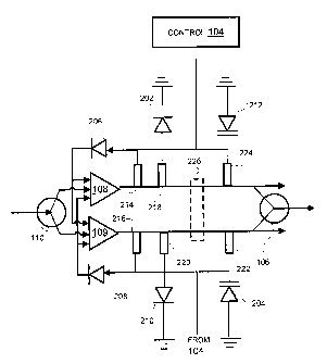
[0049] Figure 2 is a more detailed block diagram of an embodiment of the
circuit of Figure 1
including a four-quadrant linearizer (FQL) 102. Non-linear feedback circuits
111 and 112
may include, in some embodiments, impedance elements 214 and 216,
respectively, and
diodes 206 and 208, respectively. The FQL 102 may further comprise impedance
elements
218, 224, 220, and 222. In some implementations the impedance elements may be
substantially resistive in nature. The positive real component of the
generated pre-distortion
vector may be controlled by affecting the current through diodes 202 and 206.
The negative
real component of the generated pre-distortion vector may be controlled by
affecting the
current through diodes 208 and 210. The positive imaginary component of the
generated pre-
distortion vector may be controlled by affecting the voltage at varactor 212.
The negative
imaginary component of the generated pre-distortion vector may be controlled
by affecting
the voltage at varactor 204.
[0050] An optional amplification phase 226 may be provided in the circuit to
affect pre-
distortion signal levels.
[0051] Those skilled in the art will appreciate that equivalent circuit
function may be
achieved using other electronic components/configurations and/or combinations
thereof. One
example would be the use of discrete diodes and capacitors in place of
varactors in certain
implementations. In some implementations it may also be possible to achieve
the non-linear
effects of diodes using other circuit elements.
[0052] Figure 3 is an embodiment of a multiple transmitter/receiver
communication system
employing FQLs. A pair of transmitters 302 307 each comprises an FQL (304 and
303
respectively) where each FQL is used such that the signals are pre-shaped to
reduce the effect
of laser clipping, a detrimental effect that occurs when lasers 306' and 305
are modulated to
the point that the light output reaches zero. Each transmitter 302 307 may
modulate light of a
different frequency. The pre-shaped signals are provided to a combiner 308 and
communicated to a splitter 310, where they are separated again into signals of
different
wavelengths.
[0053] The pre-shaping adds distortions to the modulated signal that are fed
to receivers 312
313, where the signals are detected by detectors 314 315 and applied to a re-
shaping circuit
316 317, essentially a distortion generator that provides distortions opposite
to those
introduced by the pre-shaping such that the distortions are cancelled out. In
the case of a
CA 02611756 2007-12-11
WO 2007/075191
PCT/US2006/023641
-9-
multi-wavelength system there still is crosstalk between the channels and this
crosstalk can
be monitored in the receiver outputs by a crosstalk monitor 320, for instance
by monitoring a
pilot tone that is injected at (one of) the transmitters 302 307. The monitor
signal voltage is
then used to control a voltage-controlled combiner network (VCCN) 318 that
combines the
receiver outputs such that the crosstalk signal is cancelled. The receivers
312 313 may also
monitor the output of the VCCN 318 to zero crosstalk by using a feedback from
the output to
the monitor block 320.
[0054] In some implementations the FQLs 304 303 in the transmitters 302 307
may be used
to generate signal pre-shaping to avoid laser clipping in such a way that the
distortions are out
of the signal band. This allows reconstruction of the original signals at the
receivers 312 313
by simple filtering of the out of band distortion signals, or, in the case
where the presence of
out of band signals does not affect system operation, even the filter step may
be skipped.
[0055] Figure 4 shows an embodiment with a multi-wavelength communication
system
where the crosstalk between channels is measured at the output of the system.
A VCCN 318
at the output is driven such that the crosstalk is minimized. This or a
different VCCN 418
may also reside at the transmitter end of the system and may receive feedback
signals from
the crosstalk monitor 320 at the receiver end, for example through the return
path of the
communication system. Alternately one may use a combiner network in the
receiver that is
controlled using feedback by monitoring the crosstalk in the output of that
combiner network.
[0056] The previous discussion has been directed to the use of FQLs in
transmitters.
However, the same type of technology can be applied in receivers as well.
[0057] Figure 5 is a block diagram of a head end 502 comprising two
transmitters 506 508,
each configured to transmit the same signal, where one signal is linearly
polarized and other
signal is perpendicularly polarized. The outputs of the transmitters 506 508
are sent to a
polarization maintaining combiner 510 via polarization maintaining fibers. The
combined
signals are sent via a nounal fiber, which introduces various distortions,
including SRS. The
signals are then received at a receive node 504 and split in a DWDM demux 512
and fed to
respective receivers 514 516. Because SRS is polarization dependent, the SRS
effect can be
mitigated by maintaining orthogonal polarization signals.
[0058] Figure 6 is a block diagram of an implementation comprising a multiple
wavelength
transmitter where more than two transmitters 606...608 are operated with
different
polarization values. The differences in polarization values can be uniformly
separated (e.g.,
by 90/n or 360/n). In another embodiment, the differences in polarization
values are not
uniformly separated. In one embodiment, the polarization values can be fixed
or manually
adjustable. In another embodiment, the exists a means to control the relative
polarization state
CA 02611756 2013-10-30
of the individual transmitters. In this embodiment, the receivers 614...616,
via a return path not shown,
report on SRS and other distortion effects, allowing for the respective
transmitter to adjust the
polarization to compensate for the SRS and other distortion observed by the
receiver.
[0059] Figure 7 shows another embodiment where the inputs to the two
transmitters include unique
narrowcast signals (NCI and NC2) and a common broadcast signal (BC). In yet
another embodiment
not shown, the inputs to the two transmitters include unique narrowcast
signals and broadcast signals.
In these embodiments, there is an additional input on the transmitters for low
frequency signals that
have shared information for the two (or more) output channels, whereas
separate inputs are used for
high frequency without shared information between the two channels.
[0060] SRS maybe less prominent at high modulation frequencies. Thus, another
embodiment of the
present invention is a transmitter with means tp change the modulation
frequency spectrum present in
the input signal spectrum. This would include an up converter in the
transmitter to transpose at least
part of the spectrum to a higher frequency.
[0061] In another embodiment, plural transmitters are fed by respective QAM
filters to prevent and/or
mitigate clipping. Techniques include those disclosed in Applicants' U.S.
Patent 6,583,906 as well as
U.S. Patent 6,549,316. These techniques may be used in combination with the
previously described
FQL. Alternatively, it is possible to use the techniques disclosed in
Applicants' U.S. Patent 6,271,944
relative to laser wavelength control. These techniques may be used in
combination with the previously
described FQL.
[0062] SRS gain may drop when signal separation exceeds 110 nm. Thus another
embodiment of the present invention includes a CWDM system with greater than
110 nm channel
separation. Furthermore, transmitters with multiple wavelength outputs for
example dual outputs that
are separated by more than 80 nm are desirable (e.g., 1310 and 1550 nit).
[0063] SRS may be driven by the power envelope of the signal. Thus in one
embodiment, a transmitter
with a constant power output and phase modulator signal output is used. A
receiver is used to detect
the phase modulator output signal.
[0064] SRS may, in some implementations, primarily be a crosstalk phenomenon.
Thus, in one
embodiment, there is a transmitter with multiple inputs and outputs is used
where signals from the
inputs are filtered, level and phase are adjusted, and recombined before being
sent to the optical
outputs in such a way that the crosstalk between the channels on the fiber
link is reduced.
CA 02611756 2007-12-11
WO 2007/075191
PCT/US2006/023641
-11-
[0065] Furthermore, another embodiment includes a corresponding receiver
system with
multiple inputs and outputs where signals from the inputs are filtered,
adjusted in level and
phase, and recombined before being sent to the optical outputs in,such a way
the crosstalk
channels of the receiver fiber link is reduced.
[0066] Any one or combination of the above systems may be used with feedback
control to
control the combination of the input signals. Feedback control may be derived
from the
signals and/or from any added pilot reference signals or tones. Any one of the
above
described systems may optionally generate distortion signals which are added
to the output
such that the distortion signals are based on a combination of two or more
available inputs.
[0067] The embodiments of Figures 5-7 or as otherwise discussed previously may
be
combined with each other and/or with the FQL of Figures 1-2 in a modular
fashion that
enables lower production costs, easier maintenance and repair, and that will
launch better
SRS/dispersion compensated light from the transmitter to the receivers.
[0068] All of the preceding techniques and devices may be adapted to DWDM
embodiments.
This involves transmission in lambda pairs to maintain total powpr and also to
improve CNR,
with the pairs modulated with (partly) the same information. Such embodiments
require a
DWDD and dual receivers. Also, semiconductor optical amplifiers (SOA) may be
used. One
advantage of an SOA over an EDFA is that an SQA has a gain flatness over a
wide
wavelength range. In one embodiment, a DWDM system with one 1550 nm pair
and/or one
1310 nm pair (4 wavelengths/fiber) is used for full performance downstream. In
this
embodiment, signals are launched with orthogonal polarization states. In
another
embodiment, encoded information about the wavelength is sent to the receiver
assist the
receiver in identifying the linearization needed on the transmit end. In
another embodiment,
wavelength information is transmitted in the forward and reverse path. The
transmitted
wavelength information is used to construct a map of the analog access system
so as to
identify and report the unidirectional or bi-directional transport of
wavelengths. This
information is used to mitigate SRS and chromatic dispersion in concert with
the previously
described FQL. This technique is application to all transmitters, be they
forward or reverse,
coax or cooled, or part of pluggable transceiver or a discrete device.
[0069] While the discussion has focused on the SRS, there is also an
additional cross phase
modulation crosstalk effect that may be addressed. This cross phase modulation
crosstalk
phenomenon worsens in direct proportional to the input power, frequency, and
dispersion and
in inverse proportion to separation of wavelengths. In the case of analog
transmission of
around 20km, SRS may be the dominating crosstalk. Cross phase modulation
asserts itself
CA 02611756 2007-12-11
WO 2007/075191
PCT/US2006/023641
-12-
however when the fiber distances are greater and when the wavelength
separation is smaller
thus attaining importance in DWDM transport for intermediate distances.
[0070] With a proliferation of multiple wavelength analog systems as described
above, there
will be a need for pluggable analog optical modules similar to conventional
single
wavelength digital modules. However, currently there are no analog grade
pluggable
transceiver modules in the market. Thus, another embodiment of the present
invention
includes the packaging of any one of the previously described devices into an
analog grade
module that is pluggable in a headend and/or in field optical nodes. Another
embodiment of
the present invention is a quasi-analog grade module that is pluggable in a
headend and in
field optical nodes. Another embodiment of the present invention is a multi
wavelength
pluggable module configured to enable bi-directional analog and quasi-analog
transmission
so as to enable forward operation on a single fiber. Another embodiment of the
present
invention is a multi wavelength bidirectional module in which the optical and
electronic
characteristics are separated such that the module can fit into a variety of
optical transport
platforms interchangeably. Other embodiments of the present invention include
a pluggable
transmitter, receiver and transceiver modules for single fiber or multi-fiber
analog transport
or quasi-analog transport.
[0071] In one embodiment, the optical laser and its driver are collocated on a
single small
board, optionally with the FQL, and the anti-clipping circuitry. This device
is be the size of a
GBIC (gigabit integrated circuit) or the SFP (small form pluggable) as defined
by the
respective GEIC and SFP commercial standards. The ability to compress in size
the opto-
electronic circuitry has the benefit of increasing density and deployment in
already crowded
headends and hubs and for promoting plug and play of optical components to
enable faster
deployments. The device may include a plug-in laser with the following defined
characteristics: Wavelength, Power and PM output. A coax and butterfly package
may also
be included. The device may include an EPROM containing laser information such
as
Wavelength, Power Output, and transmitter serial number. The bias circuit may
be located on
a main board, supplying bias to a photodiode (PD) and to the laser. In the
pluggable module
is a FQL including: 550 MHz linearizer, 870 MHz, 1 GHz, CE Load, and a NTSC
Load as
built, regulated by the microprocessor with feedback from the control plane
and held over
temperature and over power levels. Feedback from the control plane connects
the forward
transmitter to the reverse transmitter. Any drift from the transmitters is
detected by the
respective receiver and is then passed on to the adjacent transmitter for
transmission to the
corresponding receiver adjacent to the transmitter. The package may include
the ability to
create these linkages and to close-loop monitor and adjust the system.
CA 02611756 2013-10-30
-13-
[0072] Some implementations may involve a graphical user interface (GUI)
whereby an administrator
may select which types of distortion cancellation to apply. For example, the
GUI may have a tab
whereby fiber dispersion cancellation may be turned on or off, and whereby the
level of dispersion
cancellation to apply may be selected. The GUI may have another tab whereby
the user may select
whether to add compensation for cross-modulation in multi-wavelength
applications. The GUI may
include selections for which wavelengths are present in the system.
[0073] Selections from the GUI may result in predetermined setpoints applied
to the various
diodes/varactors of the FQL 102.
[0074] In other implementations, the wavelengths used in the system may be
automatically detected
and pre-distortion settings applied automatically. For example, in 1310 nm
single-wavelength
applications there may be no need for significant dispersion compensation or
cross-modulation
compensation. Thus the only set points applied may be to correct for laser
modulation non-linearity. If
other wavelengths are detected in the system, distortion compensation for both
fiber dispersion and
cross-modulation may be applied on top of the corrections for laser non-
linearity.
[0075] Only recently have un-cooled lasers been considered for use in full QAM
fiber communications
systems (e.g., Applicants' co-pending application US Patent Application
09/896,547 filed on June 29,
2001.) More recently, techniques have been proposed for linearization over
laser output power
changes (see e.g., Applicants' co-pending application U.S. Provisional
Application 60/650,973, filed
on February 9, 2005.)
[0076] The previously described FQL may be adapted for use with an un-cooled
laser. In this
embodiment, the four quadrant linearization receives a control signal relating
to bias current changes.
This control signal may he a manual and/or automatic signal that allows the
FQL to match the
changing distortion profile of the power variant laser. This embodiment of the
FQL technique is used
across the entire range or a sub-range of optical output power of an un-cooled
laser to match the
changing distortion performance of the laser generator. Also, the FQL
technique is again adapted to
receive control signals relative to temperature, power, and positive or
negative fiber chromatic
dispersion characteristics. In all embodiments, whether for cooled or un-
cooled lasers, the previously
described FQL techniques may be used in combination with other techniques
aimed at reducing or
eliminating fiber effects and non-linearities such as SRS, XPM or SPM
individually or in combination.
[0077] Of the various distortions associated with multi-wavelength systems,
stimulated Raman
scattering (SRS) cross-talk is often the main limiter in the systems. SRS is a
function
CA 02611756 2007-12-11
WO 2007/075191
PCT/US2006/023641
-14-
of power output, wavelength, total power in the fiber, number of Wavelengths,
spacing of
optical wavelengths, fiber distance/length, fiber dispersion, RF frequency and
state of
polarizations. These parameters interplay in very complex ways to cause
dispersion. SRS has
a 1/f dependence. That is, at low frequencies (e.g., 50 MHz) SRS is very high.
However as
frequency increases SRS decreases so that at 500 MHz to I GHz the SRS is low.
The
preceding comments assume two signals and SRS associated with the two signals.
[0078] SRS crosstalk may vary as a function of frequency separation between
two signals.
SRS crosstalk is very low at 10-20 nm separation. However SRS crosstalk
increases reaching
a maximum around 100 nm of separation. SRS crosstalk drops to a minimum
occurring
around 140 nm and stays relatively flat as separation increases from there.
[0079] SRS may also vary as a function of polarization and chromatic
dispersion. As
dispersion increases, SRS decreases. Thus, a good scenario may include two
orthogonal
signals carrying a signal greater than 500 MHz and with a spacing of less than
20 nm
between the two signals or greater than 140 nm between the two signals, and
over a fiber with
high dispersion. Past 10 km, cross talk is a significant degradation in modem
cable
distribution systems. SRS is less prominent for orthogonal polarization
states. That is, SRS
varies with polarization. Thus one aspect of the present invention is directed
to a dual
transmitter with a combiner that combines into output wavelengths of the
transmitter in an
orthogonal polarization state. Each wavelength is capable of carrying its own
modulation
signal that may or may not in part carry the same information as the other
signal. Launching
different wavelengths of mutually orthogonal polarization may result in
reduced SRS cross-
modulation. One or more FQLs may also be driven to cancel coMposite second
order
distortion (and distortion in general) attributable to SRS cross-modulation.
Formulas for
determining SRS cross-modulation are well known in the art.
[0080] An application of an FQL as described herein to linearizing an un-
cooled laser may
involve:
1. Compute desired monitor current, this may be a fixed current or a value
based on customer
input representing a desired output power
2. Adjust laser bias to obtain desired monitor current
3. Adjust FQL set points according to present laser bias and laser temperature
(optionally
derived from module temperature)
[0081] Here the set points follow a predefined relation with laser.bias and
temperature that is
designed in and with parameters that result from final testing. Final testing
may include laser
testing at more than one temperature
CA 02611756 2007-12-11
WO 2007/075191
PCT/US2006/023641
-15-
[0082] Another application of an FQL as described herein to linearizing an un-
cooled laser
may involve:
1. Compute desired monitor current, this may be a fixed current or a value
based on customer
input representing a desired output power
2. Adjust laser bias to obtain desired monitor current
3. Adjust FQL set points in order to keep distortion monitor signals stable.
[0083] Here the set points are adjusted (with an iterative routine) to keep
the distortion
monitor signals stable to a predefined function. The function may include
laser bias and
temperature as variables and has additional parameters based on final testing,
this testing may
be performed at more than one temperature. Note that the pre-distortion vector
required for
different laser power and or temperature often comprises a component that
swaps sign.
[0084] Another application of an FQL as described herein to linearizing an un-
cooled laser
based on controlling monitor current may involve:
1. Compute desired monitor current, this maybe a fixed current or a value
based on customer
input representing a desired output power
2. Set desired monitor current set point and allow laser bias control HW to
stabilize to get this
monitor current
3. Adjust FQL set points according to present laser bias and laser temperature
(optionally
derived from module temperature)
[0085] Here the set points follow a predefined relation with laser bias and
temperature that is
designed in and with parameters that result from final testing. Final testing
may include laser
testing at more than one temperature. Similarly this adjustment can be based
on distortion
monitor signals
[0086] An application of an FQL as described herein in a transmitter to keep
gain and tilt
stable may involve:
1. Adjust gain, tilt and attenuator settings according to a predefined
function of module
temperature and customer input on desired gain and tilt
2. Optionally adjust the above in order to keep laser drive power constant
3. Optionally adjust the above to set laser drive power at a value depending
on laser
temperature and/or module temperature and/or customer input
[0087] An application of an FQL as described herein to compensate for fiber
distortion may
involve:
1. Monitor laser temperature and compute laser wavelength L
2. Compute fiber dispersion at laser wavelength as: Db=DS*(L-Lo) where DS is
the
dispersion slope and Lo is the fiber dispersion zero
CA 02611756 2007-12-11
WO 2007/075191
PCT/US2006/023641
-16-
3. Compute required linearization level as product of fiber length and DL
(note this can be
positive and negative depending on sign DL)
4. Set FQL set points accordingly to cancel fiber distortion.
[0088] Note that the set points may contain offsets, for instance given by
additional laser
distortion that needs cancellation and may also contain functions where the
FQL control
signals are interrelated due to circuit implementation limitation. These
functions are
predefined and parameters are preset or determined in final test. Note that
going from
positive to negative dispersion compensation requires switching distortion
vector phase from
approximately +90 to -90 degrees.
[0089] An application of an FQL as described herein to compensate for fiber
and link
distortion may involve:
1. Monitor receiver feedback signals that provide a measure of distortion in
the system
2. Adjust FQL set points distortion measured at the receiver following a
predefined
optimization scheme.
[0090] An application of an FQL as described herein to clipping noise
reduction may
involve:
1. Monitor receiver type used
2. If receiver type is de-companding type then enable companding of signals at
the
transmitter by:
Setting high CTB (compression type) and/or
Setting high CSO (superlinear type)
[0091] An application of an FQL as described herein to receiver linearization
may involve:
1. Monitor receiver type used
2. If receiver type can self-linearize then set pilot tones accordingly
[0092] Note that in the distortion monitor or level-monitoring schemes
mentioned above pilot
tones can be used. Distortion in an un-cooled laser is temperature dependent
and the
dependence is such that the vectors shift to the left as the device gets hot;
the device becomes
sub-linear at hot. At cold the device is slightly super-linear. This is seen
as a sign swap in the
real axis when the laser temperature is varied.
[0093] In view of this situation, the FQL may be configured to generate
compensating
vectors such that the sum of laser and linearizer vectors is near the origin.
The FQL may be
configured to swap the sign of the real axis component generated by the
linearizer as the laser
changes temperature. In this example the variation in the imaginary part of
the distortion
vector is not large. The process described below provides an example
implementation of a
linearizer control that allows moving the distortion vector through different
quadrants.
CA 02611756 2007-12-11
WO 2007/075191
PCT/US2006/023641
-17-
//Input variables
Laser temp //Laser temperature
//Output variables
CV_pos_Re //Control voltage to set positive real distortion
CVneg_Re //Control voltage to set negative real distortion
CV pos_hn //Control voltage to set positive imaginary
//distortion
CV_neg_Ini //Control voltage to set negative imaginary distortion
//Functions
CV_re(x) //Control voltage real axis as a function of
//required distortion vector length x
CV_im(x) //Control voltage imaginary axis as a function of
//required distortion vector length x
//Parameters
Predist_Re_ref//Real part predistorter required at reference temperature
Predist_Ini_refllIrnaginary part predistorter required at reference
//temperature
Temp_ref //Reference temperature
Temp_slope_Re //Slope of real part of distortion vector per unit
//temperature
Temp_slope_Im //Slope of imaginary part distortion vector per
//unit temperature
//Process
Re_predist= Predist_Re_ref+ Temp_slope_Re*(Laser_temp-Temp_ref)
Im_predist¨Predist_Im_ref + Temp_slope_Im*(Laser temp-Tenip_ref)
If Re_predist > 0 then
CV_pos_Re=CV_re(Re_predist)
CV_neg_Re= CV_re(0)
else
CV_neg_Re= CV re(-Re_predist)
CV_pos_Re¨CV_re(0)
end if
If Im_predist >0 then
CV pos_Im=CV_im(Im_predist)
CV_neg_Im= CV_im(0)
else
CV_neg_Im= Cy_im(-Im_predist)
CV_pos_lni=CV_im(0)
end if
//End process
[0094] In this case the parameter Temp_slope_Im is a very low value such that
the imaginary
distortion vector is not very temperature dependent. The parameter
Temp_slope_Re is large
such that over the temperature range the sign of Re_predist will swap and the
algorithm will
thus accordingly activate another branch of the linearizer to cover a new
quadrant.
CA 02611756 2007-12-11
WO 2007/075191
PCT/US2006/023641
-18-
[0095] Those having skill in the art will appreciate that there are various
vehicles by which
processes and/or systems described herein can be effected (e.g., hardware,
software, and/or
firmware), and that the preferred vehicle will vary with the context in which
the processes are
deployed. For example, if an implementer deteanines that speed and accuracy
are paramount,
the implementer may opt for a hardware and/or firmware vehicle; alternatively,
if flexibility
is paramount, the implementer may opt for a solely software implementation;
or, yet again
alternatively, the implementer may opt for some combination of hardware,
software, and/or
firmware. Hence, there are several possible vehicles by which the processes
described herein
may be effected, none of which is inherently superior to the other in that any
vehicle to be
utilized is a choice dependent upon the context in which the vehicle will be
deployed and the
specific concerns (e.g., speed, flexibility, or predictability) of the
'implementer, any of which
may vary. Those skilled in the art will recognize that optical aspects of
implementations will
require optically-oriented hardware, software, and or firmware.
[0096] The foregoing detailed description has set forth various embodiments of
the devices
and/or processes via the use of block diagrams, flowcharts, and/or examples.
Insofar as such
block diagrams, flowcharts, and/or examples contain one or more functions
and/or
operations, it will be understood as notorious by those within the art that
each function and/or
operation within such block diagrams, flowcharts, or examples can be
implemented,
individually and/or collectively, by a wide range of hardware, software,
firmware, or virtually
any combination thereof. Several portions of the subject matter subject matter
described
herein may be implemented via Application Specific Integrated Circuits
(ASICs), Field
Programmable Gate Arrays (FPGAs), digital signal processors (DSPs), or other
integrated
formats. However, those skilled in the art will recognize that some aspects of
the
embodiments disclosed herein, in whole or in part, can be equivalently
implemented in
standard integrated circuits, as one or more computer programs running on one
or more
computers (e.g., as one or more programs running on one or more computer
systems), as one
or more programs running on one or more processors (e.g., as one or more
programs running
on one or more microprocessors), as firmware, or as virtually any combination
thereof, and
that designing the circuitry and/or writing the code for the software and/or
firmware would be
well within the skill of one of skill in the art in light of this disclosure.
In addition, those
skilled in the art will appreciate that the mechanisms of the subject matter
described herein
are capable of being distributed as a program product in a variety of forms,
and that an
illustrative embodiment of the subject matter described herein applies equally
regardless of
the particular type of signal bearing media used to actually carry out the
distribution.
Examples of a signal bearing media include, but are not limited to, the
following: recordable
CA 02611756 2007-12-11
WO 2007/075191 PCT/US2006/023641
-19-
type media such as floppy disks, hard disk drives, CD ROMs, digital tape, and
computer
memory; and transmission type media such as digital and analog communication
links using
TDM or IP based communication links (e.g., packet links).
[0097] In a general sense, those skilled in the art will recognize that the
various aspects
described herein which can be implemented, individually and/or collectively,
by a wide range
of hardware, software, firmware, or any combination thereof can be viewed as
being
composed of various types of "electrical circuitry." Consequently, as used
herein "electrical
circuitry" includes, but is not limited to, electrical circuitry having at
least one discrete
electrical circuit, electrical circuitry having at least one integrated
circuit, electrical circuitry
having at least one application specific integrated circuit, electrical
circuitry forming a
general purpose computing device configured by a computer program (e.g., a
general purpose
computer configured by a computer program which at least partially carries out
processes
and/or devices described herein, or a microprocessor configured by a computer
program
which at least partially carries out processes and/or devices described
herein), electrical
circuitry forming a memory device (e.g., forms of random access memory),
and/or electrical
circuitry forming a communications device (e.g., a modem, communications
switch, or
optical-electrical equipment).
[0098] Those skilled in the art will recognize that it is common within the
art to describe
devices and/or processes in the fashion set forth herein, and thereafter use
standard
engineering practices to integrate such described devices and/or processes
into larger
systems. That is, at least a portion of the devices and/or processes described
herein can be
integrated into a network processing system via a reasonable amount of
experimentation.
[0099] The foregoing described aspects depict different components contained
within, or
connected with, different other components. It is to be understood that such
depicted
architectures are merely exemplary, and that in fact many other architectures
can be
implemented which achieve the same functionality. In a conceptual sense, any
arrangement
of components to achieve the same functionality is effectively "associated"
such that the
desired functionality is achieved. Hence, any two components herein combined
to achieve a
particular functionality can be seen as "associated with" each other such that
the desired
functionality is achieved, irrespective of architectures or intermedial
components. Likewise,
any two components so associated can also be viewed as being "operably
connected", or
"operably coupled", to each other to achieve the desired functionOity.