Language selection

Search

Patent 2611771 Summary

Third-party information liability

Some of the information on this Web page has been provided by external sources. The Government of Canada is not responsible for the accuracy, reliability or currency of the information supplied by external sources. Users wishing to rely upon this information should consult directly with the source of the information. Content provided by external sources is not subject to official languages, privacy and accessibility requirements.

Claims and Abstract availability

Any discrepancies in the text and image of the Claims and Abstract are due to differing posting times. Text of the Claims and Abstract are posted:

  • At the time the application is open to public inspection;
  • At the time of issue of the patent (grant).
(12) Patent: (11) CA 2611771
(54) English Title: POWER TONG DEVICE
(54) French Title: DISPOSITIF A TENAILLE MECANIQUE
Status: Expired and beyond the Period of Reversal
Bibliographic Data
(51) International Patent Classification (IPC):
  • E21B 19/16 (2006.01)
(72) Inventors :
  • VATNE, PER A. (Norway)
(73) Owners :
  • WELLQUIP AS
(71) Applicants :
  • WELLQUIP AS (Norway)
(74) Agent: DONALD V. TOMKINSTOMKINS, DONALD V.
(74) Associate agent:
(45) Issued: 2011-05-03
(86) PCT Filing Date: 2006-06-09
(87) Open to Public Inspection: 2006-12-21
Examination requested: 2008-08-25
Availability of licence: N/A
Dedicated to the Public: N/A
(25) Language of filing: English

Patent Cooperation Treaty (PCT): Yes
(86) PCT Filing Number: PCT/NO2006/000220
(87) International Publication Number: NO2006000220
(85) National Entry: 2007-12-11

(30) Application Priority Data:
Application No. Country/Territory Date
20052844 (Norway) 2005-06-13

Abstracts

English Abstract


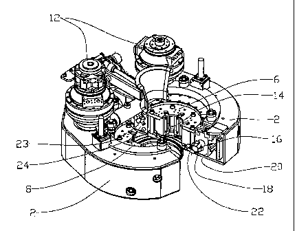
A power tong (1) device, in which the power tong (1) includes two housing
halves (2), pivotable
relative to each other, the housing halves (2) being arranged to be pivoted
between a closed, active position and an open, inactive
position, and in which a radially divided drive ring (6, 8), which is provided
with hydraulically activated clamping dies (14) directed
towards the centre axis (10) of the power tong (1), is placed in the housing
halves, the drive ring (6, 8) being supported and connected
to a driving motor (12) for the rotation of the drive ring (6, 8) about said
axis (10), the drive ring (6, 8) being provided with at least
one locking means (16) which is arranged to interconnect the parts of the
drive ring (6, 8) in a releasable manner.


French Abstract

L~invention concerne un dispositif à tenaille mécanique (1) dans lequel la tenaille mécanique (1) comprend deux moitiés de boîtier (2) pouvant pivoter l~une par rapport à l~autre, les moitiés de boîtier (2) étant disposées de sorte à pivoter entre une position active fermée et une position inactive ouverte. Un anneau d~entraînement radialement divisé (6, 8) qui est doté de plateaux de serrage à activation hydraulique (14) en direction de l~axe central (10) de la tenaille mécanique (1) est placé dans les moitiés de boîtier (2), l~anneau d~entraînement (6, 8) étant supporté par un moteur d~entraînement (12) et raccordé à celui-ci afin de faire tourner l~anneau d~entraînement (6, 8) autour dudit axe (10). L'anneau d~entraînement (6, 8) est doté d~au moins un moyen de blocage (16) qui est disposé de sorte à relier les parties de l~anneau d~entraînement (6, 8) de manière libérable.

Claims

Note: Claims are shown in the official language in which they were submitted.


8
Claims:
1. A power tong comprising:
two housing halves pivotable relative to each other,
said housing halves being arranged to be pivoted between a
closed, active position and an open, inactive position; and
a radially divided drive ring having a first and a
second drive ring part, one or more bayonet catches and a
plurality of hydraulically activated clamping dies directed
towards a centre axis of said power tong, said drive ring is
located in said housing halves, said drive ring being
supported and connected to a driving motor for the rotation
of said drive ring about said centre axis, said drive ring
and a locking means arranged to interconnect said first and
second drive ring parts in a releasable manner;
wherein, each said bayonet catch has a locking body
hydraulically rotatable between an active and a non-active
position.
2. The power tong in accordance with claim 1, said locking
body comprising at least one locking dog, said locking body
and said locking dog being located on one of said first and
second drive ring parts and fitting complementarily into a
recess in the opposite drive ring part, a rotation of said
locking body about a centre axis moving said locking dog
between the active and the non-active position.
3. The power tong in accordance with claim 2, further
comprising said bayonet catch being rotatable by a movable
index pin located in said drive ring, said index pin
cooperating with an eccentrically mounted pivot on said
locking body.

9
4. The power tong in accordance with claim 3, further
comprising said index pin being movable by a corresponding
hydraulic cylinder located in one of said housing halves.
5. The power tong in accordance with claim 3, further
comprising said bayonet catch being in the inactive position
and said index pin being moved into a piston recess in one
of said first and second housing halves.
6. The power tong in accordance with any one of claims 1 to
5, further comprising said first drive ring part and said
second drive ring part each having a radial guide list and
said drive ring parts bearing on each other along said
radial guide lists, said first and second drive ring parts
being arranged to be rotated about said guide lists in order
to relieve said bayonet catch.
7. A method for handling oilfield pipe comprising the steps
of:
positioning a drive ring about a pipe, said drive ring
having two pivotally connected, radial drive ring halves and
a plurality of clamping dies, said drive ring halves being
in an open, inactive position about the pipe;
rotating said drive ring halves to a closed, active
position about the pipe;
locking said two drive ring halves in said closed,
active position by rotating a locking body about a centre
axis, said locking body having a locking dog and being
connected to one of said two drive halves and inserting said
locking dog into a complementary recess located in said
opposite drive ring half;

activating said clamping dies to grip a surface of the
pipe;
wherein said rotating step is accomplished by a movable
index pin located in said drive ring and in communication
with an eccentrically mounted pivot on said locking body.
8. The method of claim 7 wherein said rotating step is
accomplished by a hydraulic cylinder located in said drive
half.
9. A method for handling oilfield pipe comprising the steps
of:
positioning a drive ring about a pipe, said drive ring
having two pivotally connected, radial drive ring halves and
a plurality of clamping dies, said drive ring halves being
in an open, inactive position about the pipe;
rotating said drive ring halves to a closed, active
position about the pipe;
locking said two drive ring halves in said closed,
active position;
activating said clamping dies to grip a surface of the
pipe;
deactivating said clamping dies;
releasing said two drive ring halves from said locked
position; and
rotating said drive ring so that said drive ring halves
pivot to an open, inactive position about the pipe;
wherein said releasing step is comprising moving an
index pin into a piston recess located in said corresponding
drive ring half.

Description

Note: Descriptions are shown in the official language in which they were submitted.


CA 02611771 2007-12-11
WO 2006/135248 PCT/N02006/000220
POWER TONG DEVICE
This invention relates to a power tong. More particularly it
relates to a power tong, in which the power tong comprises
two housing halves pivotable relative to each other, the
housing halves being arranged to be pivoted between a closed,
active position and an open, inactive position. A radially
divided drive ring provided with hydraulically activated
clamping dies directed towards the centre of the power tong
is placed in the housing halves, the drive ring being sup-
ported and connected to a drive for the rotation of the drive
ring about said centre axis. The drive ring is provided with
at least one bayonet catch, which is arranged to connect the
parts of the drive ring in a releasable manner.
In connection with drilling operations in the ground, in
which joinable drill pipes are used, for example in the re-
covery of petroleum, mechanized pipe tongs in the form of
power tongs are well known and extensively used.

CA 02611771 2010-03-01
2
Power tongs of this kind normally include hydraulically or
mechanically activated grippers or clamping dies which are
arranged to clamp a pipe grippingly.
It is common that power tongs either are provided with a
radial opening or can be opened, so that the power tong can
be moved in a radial direction onto and away from the pipe.
Due to the relatively great clamping forces that are
necessary when pipes are being connected, open power tongs
are often relatively heavy because they have to be sized to
be able to absorb said forces. Closed power tongs, in which
the clamping forces can be absorbed by a closed ring, are
often relatively light, but it has turned out to be
difficult to provide a closing mechanism for the power tong,
which is both strong enough and which exhibits the necessary
reliability.
The invention has as its object to remedy or reduce at least
one of the drawbacks of the prior art.
In accordance with the present invention, there is provided
a power tong comprising: two housing halves pivotable
relative to each other, said housing halves being arranged
to be pivoted between a closed, active position and an open,
inactive position; and a radially divided drive ring having
a first and a second drive ring part, one or more bayonet
catches and a plurality of hydraulically activated clamping
dies directed towards a centre axis of said power tong, said
drive ring is located in said housing halves, said drive
ring being supported and connected to a driving motor for
the rotation of said drive ring about said centre axis, said
drive ring and a locking means arranged to interconnect said
first and second drive ring parts in a releasable manner;

CA 02611771 2010-03-01
3
wherein, each said bayonet catch has a locking body
hydraulically rotatable between an active and a non-active
position.
Also, in accordance with the present invention, there is
provided a method for handling oilfield pipe comprising the
steps of: positioning a drive ring about a pipe, said drive
ring having two pivotally connected, radial drive ring
halves and a plurality of clamping dies, said drive ring
halves being in an open, inactive position about the pipe;
rotating said drive ring halves to a closed, active position
about the pipe; locking said two drive ring halves in said
closed, active position by rotating a locking body about a
centre axis, said locking body having a locking dog and
being connected to one of said two drive halves and
inserting said locking dog into a complementary recess
located in said opposite drive ring half; activating said
clamping dies to grip a surface of the pipe; wherein said
rotating step is accomplished by a movable index pin located
in said drive ring and in communication with an
eccentrically mounted pivot on said locking body.
Also, in accordance with the present invention, there is
provided a method for handling oilfield pipe comprising the
steps of: positioning a drive ring about a pipe, said drive
ring having two pivotally connected, radial drive ring
halves and a plurality of clamping dies, said drive ring
halves being in an open, inactive position about the pipe;
rotating said drive ring halves to a closed, active position
about the pipe; locking said two drive ring halves in said
closed, active position; activating said clamping dies to
grip a surface of the pipe; deactivating said clamping dies;
releasing said two drive ring halves from said locked

CA 02611771 2010-03-01
3a
position; and rotating said drive ring so that said drive
ring halves pivot to an open, inactive position about the
pipe; wherein said releasing step is comprising moving an
index pin into a piston recess located in said corresponding
drive ring half.
In one particular embodiment, the part of the bayonet catch,
which is located in a first drive ring part, includes a body
provided with locking dogs. The body with the locking dogs
fits complementarily into a recess in an opposite second
drive ring part. By rotating the bolt about its centre axis
the locking dogs may be moved between the active and the
non-active position.
Advantageously the mechanical transmission of the bayonet
catch includes an index pin located on one of the drive ring
parts, the index pin, which is moved in the axial direction
by a hydraulic piston in the corresponding housing half,
cooperating with an eccentrically mounted pivot on the
shaft.
As the drive ring parts are moved towards each other they
will bear on each other along a radial abutment guide list
which is placed at one end surface of the drive ring parts,
typically the upper end surface. The drive ring parts are
moved further towards each other so that the drive ring
parts are rotated relative to each other over a relatively
small angle about the guide lists. The bayonet catch can be
opened and closed while the drive ring parts are in these
relative positions.
With the bayonet catch in its locked position the drive ring
parts align relative to each other as the clamping dies

CA 02611771 2008-08-25
4
tighten against a pipe. The bayonet catch is thereby tight-.
ened. To lock the first and the second drive ring parts
within their respective housing halves, the index pin is,
when the bayonet catch is in its inactive position, in a re-
cess in its corresponding housing half. Thereby, it is not
possible for the drive ring parts to become displaced in the
housing halves when the bayonet catch is open.
By the connection of the drive ring parts by means of a pre-
loaded bayonet catch according to the invention, the drive
ring parts will exhibit, in their connected and tightened po-
sition, a substantially improved rigidity relative to known
divided drive rings.
In what follows is described a non-limiting example of a pre-
ferred embodiment which is visualized in the accompanying
is drawings, in which:
Figure 1 shows a power tong according to the invention;
Figure 2 shows the housing halves of the power tong in an
open position;
Figure 3 shows, on a larger scale, a drive ring;
Figure 4 shows a section III-III of Figure 3;
Figure 5 shows the same section as Figure 4, but here the
bayonet catch is in its locked, active position;
Figure 6 shows, on a further enlarged scale, a view IV-IV of
Figure 4; and

CA 02611771 2008-08-25
Figure 7 shows, on a further enlarged scale, the relative
positions of the drive ring parts during connection
and disconnection of the bayonet catch.
In the drawings the reference numeral 1 denotes a power tong,
5 which includes two housing halves 2, movable relative to each
otherand connected, jointly liftable and lowerable, to a sup-
port 4 in a manner known per se.
A two-part drive ring includes a first drive ring part 6 and
a second drive ring part 8 which can be interconnected into a
drive ring, and which are arranged to be rotated about their
own centre axis 10 by means of driving motors 12 when the
housing halves 2 are in their closed, active position, see
figure 1.
A number of clamping dies 14 which are located in the drive
is ring parts 6 and 8 are radially movable and arranged to grip
about a pipe (not shown).
The drive ring parts 6, 8 may be releasably connected to each
other by means of two bayonet catches 16.
Each of the bayonet catches 16 includes a body 18 in the form
of an axle extending in a tangential direction relative to
its respective drive ring parts 6, 8, and extending through
and out of a first connecting plate 20 of the drive ring part
6, 8 and towards the adjacent connection halves 6, 8. The
axle 18 is rotatable about its own longitudinal axis and is
provided with locking dogs 22 at its free end portion, see
figures 2, 4 and 5.

CA 02611771 2007-12-11
WO 2006/135248 PCT/N02006/000220
6
The axle 18 and the locking dogs 22 fit complementarily into
a recess 23 in a second connecting plate 24 of the adjacent
drive ring half 6, B. A lock bushing 26 prevents the axle 18
from being moved out in the axial direction relative to the
first connecting plate 20. The axle 18, locking dogs 22 and
lock bushing 26 constitute the locking body of the bayonet
catch 16.
The lock bushing 26 is provided with an eccentrically placed
pivot 28 positioned in an elongated transversal groove 30 in
an index pin 32. The index pin 32 is axially movable and ar-
ranged to take up a first position, in which the bayonet
catch 16 is in a non-active free position, see figure 4, and
a second position, in which the bayonet catch 16 has been ro-
tated into an active, locking position, see figure 5.
The index pin 32 which is spring-loaded in the direction of
its first position by means of a spring 34, extends when it
is in this first position, into a piston recess 36 in its
corresponding housing half 2.
A piston 38 extending in a cylinder 40 in the extension of
the piston recess 36, is arranged to move the index pin 32 to
its second position, in which the index pin 32 is disengaged
from the piston recess 36 and thereby is free to rotate about
the centre axis 10 of the power tong together with the drive
ring 6, 8.
At its end portion facing the piston recess 36, the index pin
32 is provided with a wheel 42, which is arranged to roll on
the piston 38 and housing halves 2.

CA 02611771 2007-12-11
WO 2006/135248 PCT/N02006/000220
7
At their abutting faces the drive ring parts 6 and 8 are pro-
vided with radial guide lists 44. The guide lists 44 are at
the upper side of the drive ring parts 6, 8. When the drive
ring parts 6, 8 bear on each other at their respective guide
s lists 44, the first connecting plate 20 has some clearance to
the corresponding second connecting plate 24.
By moving the drive ring parts '6, 8 further together, the re-
spective drive ring parts 6, 8 are rotated about their re-
spective guide lists 44 until the adjacent connecting plates
20, 24 meet, see figure 7. While the drive ring parts 6, 8
are in this position, the axle 18 can freely be rotated be-
tween the locked and free positions.
The bayonet catch 16 is tightened in its locked position by
the tightening of the clamping dies 14 against the pipe (not
shown).
Due to the engagement of the index pin 32 in the piston re-
cess 36 the respective drive ring parts 6, 8 are prevented
from being rotated out of their respective housing halves 2
while the housing halves are in their open position. The
housing halves 2 are prevented from being rotated from their
closed position until the drive ring parts 6, 8 are locked
within their respective housing halves 2.

Representative Drawing
A single figure which represents the drawing illustrating the invention.
Administrative Status

2024-08-01:As part of the Next Generation Patents (NGP) transition, the Canadian Patents Database (CPD) now contains a more detailed Event History, which replicates the Event Log of our new back-office solution.

Please note that "Inactive:" events refers to events no longer in use in our new back-office solution.

For a clearer understanding of the status of the application/patent presented on this page, the site Disclaimer , as well as the definitions for Patent , Event History , Maintenance Fee  and Payment History  should be consulted.

Event History

Description Date
Time Limit for Reversal Expired 2023-12-11
Letter Sent 2023-06-09
Letter Sent 2022-12-09
Letter Sent 2022-06-09
Common Representative Appointed 2019-10-30
Maintenance Request Received 2013-07-05
Inactive: Late MF processed 2013-07-05
Letter Sent 2013-06-10
Revocation of Agent Requirements Determined Compliant 2012-12-06
Inactive: Office letter 2012-12-06
Appointment of Agent Requirements Determined Compliant 2012-12-06
Revocation of Agent Request 2012-11-26
Appointment of Agent Request 2012-11-26
Grant by Issuance 2011-05-03
Inactive: Cover page published 2011-05-02
Pre-grant 2011-02-14
Inactive: Final fee received 2011-02-14
Letter Sent 2010-09-21
Notice of Allowance is Issued 2010-09-21
Inactive: Approved for allowance (AFA) 2010-09-16
Amendment Received - Voluntary Amendment 2010-03-01
Inactive: S.30(2) Rules - Examiner requisition 2009-09-01
Letter Sent 2008-10-17
Amendment Received - Voluntary Amendment 2008-08-25
Request for Examination Received 2008-08-25
Request for Examination Requirements Determined Compliant 2008-08-25
Amendment Received - Voluntary Amendment 2008-08-25
All Requirements for Examination Determined Compliant 2008-08-25
Letter Sent 2008-04-01
Inactive: Declaration of entitlement/transfer requested - Formalities 2008-03-18
Inactive: Cover page published 2008-03-12
Inactive: Notice - National entry - No RFE 2008-03-10
Inactive: Single transfer 2008-01-21
Inactive: First IPC assigned 2008-01-10
Application Received - PCT 2008-01-09
National Entry Requirements Determined Compliant 2007-12-11
Application Published (Open to Public Inspection) 2006-12-21

Abandonment History

There is no abandonment history.

Maintenance Fee

The last payment was received on 2010-05-17

Note : If the full payment has not been received on or before the date indicated, a further fee may be required which may be one of the following

  • the reinstatement fee;
  • the late payment fee; or
  • additional fee to reverse deemed expiry.

Patent fees are adjusted on the 1st of January every year. The amounts above are the current amounts if received by December 31 of the current year.
Please refer to the CIPO Patent Fees web page to see all current fee amounts.

Owners on Record

Note: Records showing the ownership history in alphabetical order.

Current Owners on Record
WELLQUIP AS
Past Owners on Record
PER A. VATNE
Past Owners that do not appear in the "Owners on Record" listing will appear in other documentation within the application.
Documents

To view selected files, please enter reCAPTCHA code :


To view images, click a link in the Document Description column. To download the documents, select one or more checkboxes in the first column and then click the "Download Selected in PDF format (Zip Archive)" or the "Download Selected as Single PDF" button.

List of published and non-published patent-specific documents on the CPD .

If you have any difficulty accessing content, you can call the Client Service Centre at 1-866-997-1936 or send them an e-mail at CIPO Client Service Centre.


Document
Description 
Date
(yyyy-mm-dd) 
Number of pages   Size of Image (KB) 
Description 2007-12-10 7 256
Claims 2007-12-10 2 68
Representative drawing 2007-12-10 1 21
Abstract 2007-12-10 1 70
Drawings 2007-12-10 5 122
Description 2008-08-24 7 247
Description 2010-02-28 8 297
Claims 2010-02-28 3 113
Abstract 2011-04-10 1 70
Representative drawing 2011-04-12 1 22
Notice of National Entry 2008-03-09 1 195
Courtesy - Certificate of registration (related document(s)) 2008-03-31 1 105
Acknowledgement of Request for Examination 2008-10-16 1 175
Commissioner's Notice - Application Found Allowable 2010-09-20 1 163
Maintenance Fee Notice 2013-07-15 1 171
Late Payment Acknowledgement 2013-07-15 1 164
Commissioner's Notice - Maintenance Fee for a Patent Not Paid 2022-07-20 1 541
Courtesy - Patent Term Deemed Expired 2023-01-19 1 537
Commissioner's Notice - Maintenance Fee for a Patent Not Paid 2023-07-20 1 540
PCT 2007-12-10 4 108
Correspondence 2008-03-09 1 26
Correspondence 2011-02-13 2 64
Correspondence 2012-11-25 2 69
Correspondence 2012-12-05 1 13
Correspondence 2012-12-05 1 16
Fees 2013-07-04 1 34