Note: Descriptions are shown in the official language in which they were submitted.
CA 02611819 2007-11-22
213975
METHOD FOR SELECTIVELY REMOVING COATINGS
FROM METAL SUBSTRATES
BACKGROUND
The present invention is generally directed to methods of removing a coating
from a substrate. More particularly, the invention relates to the removal of
coatings
poor in aluminum (Al) content from a metal substrate, e.g., a superalloy
component.
A variety of coatings are used to provide oxidation resistance and thermal
barrier properties to metal articles, such as turbine engine components.
Coatings
currently used on components of gas turbine hot sections, such as blades,
nozzles,
combustors, and transition pieces, generally belong to one of two classes,
diffusion
coatings or overlay coatings. State-of-the-art diffusion coatings are
generally formed
of aluminide-type alloys, such as nickel-aluminide, platinum-aluminide, or
nickel-
platinum-aluminide.
Overlay coatings typically have the composition MCrAI(X), where M is an
element from the group consisting of Ni, Co, Fe, and combinations thereof, and
X is
an element from the group consisting of Y, Ta, Si, Hf, Ti, Zr, B, C, and
combinations
thereof. Diffusion coatings are formed by depositing constituent components of
the
coating on the article and reacting those components with elements from the
underlying substrate of the article to form the coating by high temperature
diffusion.
In contrast, overlay coatings are generally deposited intact, without reaction
with the
underlying substrate.
When gas turbines are serviced, the protective coatings usually must be
removed from various components to permit inspection and possible repair of
the
underlying substrate. Removal of the coatings is typically carried out by
immersing
the components in a stripping solution. A variety of stripping techniques are
currently
available for removing different types of coatings from metal substrates. The
-1-
CA 02611819 2007-11-22
213975
techniques usually must exhibit a considerable amount of selectivity to remove
only
intended materials, while generally preserving the components' desired
structures.
Methods have been previously described for selectively removing Al-based
coatings by contacting the coating with an aqueous composition which comprises
an
acid having the formula H,AF6. Usually, A is selected from the group
consisting of Si,
Ge, Ti, Zr, Al, and Ga; and x is 1-6. These methods have generally been
effective in
selectively removing Al-based overlay coatings and diffusion coatings from
substrate
materials.
It has been recognized that MCrA1(X) coatings with less that about 12% Al
by weight can have better high temperature (for example in the 2000 -2100 F.
range) creep and stress rupture resistance than those with higher Al content,
resulting
in more use of McrAl(X) coatings with less than about 12% Al by weight. These
Al-
poor coatings, however, are highly resistant to the selective stripping
methods
described above. Without an effective selective stripping process to remove
these Al-
poor coatings, non-selective methods must be relied on, such as very strong
non-
selective acids or aggressive mechanical methods, both of which can cause
damage to
the substrate. To reduce the risk of damaging the substrate during the process
of
coating removal, what is needed is an effective method for selectively
removing Al-
poor coatings from the substrate.
BRIEF DESCRIPTION
Embodiments of the present invention solve the aforementioned challenges
through a method for selectively removing a coating from a substrate in which
aluminum is diffused into the coating.
The coating is brought into contact with an aqueous composition including at
least one of an acid having the formula H,tAF6, and precursors to the acid. A
is
selected from the group consisting of Si, Ge, Ti, Zr, Al, and Ga, and x is 1-
6.
These and other advantages and features will be more readily understood
from the following detailed description of embodiments of the invention that
is
provided in connection with the accompanying drawings.
-2-
CA 02611819 2007-11-22
213975
BRIEF DESCRIPTION OF THE DRAWINGS
FIG. 1 is an illustration of a selective stripping system constructed in
accordance with an embodiment of the invention.
DETAILED DESCRIPTION
As described above, aluminum-poor coatings, for example those having the
composition MCrAl(X), where M is an element from the group consisting of Ni,
Co,
Fe, and combinations thereof, and X is an element from the group consisting of
Y, Ta,
Si, Hf, Ti, Zr, B, C, and combinations thereof, and where an Al content is
less than
about 12% by weight, are highly resistant to known selective stripping
methods. By
diffusing additional Al into the Al-poor coating, however, the Al-poor coating
can be
made removable by selective stripping.
In one embodiment, Al is diffused into the Al-poor coating by treating the
Al-poor coating with a slurry which includes colloidal silica and particles of
an
aluminum-based powder. The term "colloidal silica" is meant to embrace any
dispersion of fine particles of silica in a medium of water or another
solvent.
Dispersions of colloidal silica are available from various chemical
manufacturers, in
either acidic or basic form. Moreover, various shapes of silica particles can
be used,
e.g., spherical, hollow, porous, rod, plate, flake, or fibrous, as well as
amorphous
silica powder. Spherical silica particles are often utilized. The particles
usually have
an average particle size in the range of about 10 nanometers to about 100
nanometers.
The amount of colloidal silica present in the composition depends on various
factors. The factors include, for example: the amount of aluminum-based powder
being used; and the presence and amount of an organic stabilizer, as described
below.
Processing conditions are also a consideration, e.g., how the slurry is formed
and
applied to the coating. Usually, the colloidal silica is present at about 5%
by weight to
about 20% by weight, based on silica solids as a percentage of the entire
composition.
In some embodiments, the amount is in the range of about 10% by weight to
about
15% by weight.
-3-
CA 02611819 2007-11-22
213975
The slurry composition further includes an aluminum-based powder. This
powder serves as the source of aluminum diffused into the coating. The
aluminum-
based powder can be obtained from a number of commercial sources, such as
Valimet
Corporation, Stockton, Calif. The powder is usually in the form of spherical
particles.
However, it can be in other forms as well, such as those described above for
the
colloidal silica, or in the form of a wire, e.g., wire mesh.
A variety of standard sizes of aluminum-based powder particles can be used.
The size of the powder particles will depend on several factors, such as the
type of
coating; the technique by which the slurry is to be applied to the coating;
the identity
of the other components present in the slurry; and the relative amounts of
those
components. Usually, the powder particles have an average particle size in the
range
of about 0.5 micron to about 200 microns. In some embodiments, the powder
particles
have an average particle size in the range of about 1 micron to about 50
microns. In
other embodiments, the average particle size is in the range of about 1 micron
to about
20 microns. The powder particles are often produced by a gas atomization
process,
although other techniques can be employed, e.g., rotating electrode
techniques.
As used herein, an "aluminum-based powder" is defined as one which
contains at least about 75% by weight aluminum, based on total elements
present. For
example, the powder may contain at least one platinum group metal, such as
platinum,
palladium, ruthenium, rhodium, osmium, and iridium. Rare earth metals are also
possible, e.g., lanthanides such as lanthanum, cerium, and erbium. Elements
which are
chemically similar to the lanthanides could also be included, such as scandium
and
yttrium. In some instances, it may also be desirable to include one or more of
iron,
chromium, and cobalt. Moreover, those skilled in the art understand that
aluminum-
based powder may also contain various other elements and other materials at
impurity
levels, e.g., less than about 1% by weight. Techniques for preparing powders
formed
from any combination of the optional elements described above are also well-
known
in the art.
The composition of the aluminum-based powder and the composition of the
slurry depend in large part on the amount of aluminum needed for application
to the
-4-
CA 02611819 2007-11-22
213975
coating. The amount of aluminum in the slurry is often in the range of about
0.5% by
weight to about 45% by weight. In other embodiments, the amount of aluminum is
in
the range of about 30% by weight to about 40% by weight. Depending on the
particular requirements for the coating, i.e., its surface region, these
aluminum levels
may be adjusted.
In one embodiment, the aluminum is present in the form of an aluminum-
silicon alloy. Frequently, the alloy is in powder form, and is available from
companies
like Valimet Corporation. Alloy powders of this type usually have a particle
size in
the range described above for the aluminum-based powders. They are often
formed
from a gas atomization process.
The silicon in the aluminum-silicon alloy serves, in part, to decrease the
melting point of the alloy, thereby facilitating the aluminiding process, as
described
below. In some embodiments, the silicon is present in an amount sufficient to
decrease the melting point of the alloy to below about 610 C. Usually, the
silicon is
present in the alloy in the range of about 1% by weight to about 20% by
weight, based
on the combined weight of the silicon and aluminum. In some other embodiments,
the
silicon is present at a level in the range of about 10% by weight to about 15%
by
weight.
As in the case of the powders described above, the aluminum-silicon alloys
may also contain one or more other elements which impart a variety of desired
characteristics. Examples include the platinum group metals; rare earth metals
(as
well as Sc and Y); iron, chromium, cobalt, and the like. Minor amounts of
impurities
are also sometimes present.
In another embodiment, the slurry includes an organic stabilizer in addition
to the colloidal silica and the aluminum (or aluminum-silicon) component. The
stabilizer is an organic compound which contains at least two hydroxyl groups.
In
other embodiments, the stabilizer contains at least three hydroxyl groups.
Stabilizers
which are water-miscible are also sometimes utilized, although this is often
not a
critical requirement. Moreover, a combination of two or more organic compounds
could be used as the stabilizer.
-5-
CA 02611819 2007-11-22
213975
A variety of organic compounds can be used as the stabilizer. Non-limiting
examples include alkane diols (sometimes referred to as "dihydroxy alcohols")
such
as ethanediol, propanediol, butanediol, and cyclopentanediol. (Some of these
dihydroxy alcohols are referred to as "glycols", e.g., ethylene glycol,
propylene
glycol, and diethylene glycol). The diols can be substituted with various
organic
groups, i.e., alkyl or aromatic groups. Non-limiting examples of the
substituted
versions include 2-methyl-1,2-propanediol; 2,3-dimethyl-2,3-butanediol; 1-
phenyl-
1,2-ethanediol; and 1-phenyl-1,2-propanediol. Another example of the organic
stabilizer is glycerol, C3H5(OH)3. The compound is sometimes referred to as
"glycerin" or "glycerine". Glycerol can readily be obtained from fats, i.e.,
glycerides.
Compounds containing greater than three hydroxy groups (some of which are
referred
to as "sugar alcohols") can also be used. As an example, pentaerythritol,
C(CH2OH)4,
can be a suitable stabilizer. Sorbitol and similar polyhydroxy alcohols
represent other
examples.
Various polymeric materials containing at least two hydroxy groups can also
be employed as the organic stabilizer. Non-limiting examples include various
fats
(glycerides), such as phosphatidic acid (a phosphoglyceride). Carbohydrates
represent
another broad class of materials that may be employed. The term "carbohydrate"
is
meant to include polyhydroxy aldehydes, polyhydroxy ketones, or compounds that
can be hydrolyzed to them. The term includes materials like lactose, along
with
sugars, such as glucose, sucrose, and fructose. Many related compounds could
also be
used, e.g., polysaccharides like cellulose and starch, or components within
the
polysaccharides, such as amylose. Water-soluble derivatives of any of these
compounds are also known in the art, and can be used herein. Based on factors
such
as cost, availability, and effectiveness, glycerols and dihydroxy alcohols
like the
glycols are often utilized as the organic stabilizer.
The amount of the organic stabilizer which should be used depends on
various factors. The factors include: the specific type of stabilizer present;
the
hydroxyl content of the stabilizer; its water-miscibility; the effect of the
stabilizer on
the viscosity of the slurry composition; the amount of aluminum present in the
slurry
composition; the particle size of the aluminum; the surface-to-volume ratio of
the
-6-
CA 02611819 2007-11-22
213975
aluminum particles; the specific technique used to prepare the slurry; and the
identity
of the other components which may be present in the slurry composition.
In some embodiments, the organic stabilizer is present in an amount
sufficient to chemically stabilize the aluminum or aluminum-silicon component
during contact with water or any other aqueous components. The term
"chemically
stabilize" is used herein to indicate that the slurry remains substantially
free of
undesirable chemical reactions. These are reactions which would increase the
viscosity and/or the temperature of the composition to unacceptable levels.
For
example, unacceptable increases in temperature or viscosity are those which
could
prevent the slurry composition from being easily applied to the substrate,
e.g., by
spraying. Usually, the amount of organic stabilizer present in the slurry
composition is
in the range of about 0.1 % by weight to about 20% by weight, based on the
total
weight of the composition. In other embodiments, the range is about 0.5% by
weight
to about 15% by weight.
As mentioned above, the slurry is usually aqueous. In other words, it includes
a liquid carrier which is primarily water, i.e., the medium in which the
colloidal silica
is often disposed. As used herein, "aqueous" refers to compositions in which
at least
about 65% of the volatile components are water. In some embodiments, at least
about
80% of the volatile components are water. Thus, a limited amount of other
liquids
may be used in admixture with the water. Non-limiting examples of the other
liquids
or "carriers" include alcohols, e.g., lower alcohols with 1-4 carbon atoms in
the main
chain, such as ethanol. Halogenated hydrocarbon solvents are another example.
Selection of a particular carrier composition will depend on various factors,
such as:
the evaporation rate required during treatment of the substrate with the
slurry; the
effect of the carrier on the adhesion of the slurry to the substrate; the
solubility of
additives and other components in the carrier; the "dispersability" of powders
in the
carrier; the carrier's ability to wet the coating and modify the rheology of
the slurry; as
well as handling requirements, cost requirements, and environmental/safety
concerns.
Those of ordinary skill in the art can select the most appropriate carrier
composition
by considering these factors.
-7-
CA 02611819 2007-11-22
213975
The amount of liquid carrier employed is usually the minimum amount
sufficient to keep the solid components of the slurry in suspension. Amounts
greater
than that level may be used to adjust the viscosity of the slurry, depending
on the
technique used to apply the slurry to the coating. In general, the liquid
carrier will
comprise about 30% by weight to about 70% by weight of the entire slurry.
A variety of other components may be used in the slurry. Most of them are
well-known in areas of chemical processing and ceramics processing. Non-
limiting
examples of these additives are thickening agents, dispersants, deflocculants,
anti-
settling agents, anti-foaming agents, binders, plasticizers, emollients,
surfactants, and
lubricants. In general, the additives are used at a level in the range of
about 0.01 % by
weight to about 10% by weight, based on the weight of the entire slurry.
For embodiments in which the slurry is based on colloidal silica and the
aluminum-silicon alloy, there are no critical steps in preparing the slurry.
Conventional blending equipment can be used, and the shearing viscosity can be
adjusted by addition of the liquid carrier. Mixing of the ingredients can be
undertaken
at room temperature, or at temperatures up to about 60 C., e.g., using a hot
water bath
or other technique. Mixing is carried out until the resulting slurry is
uniform. The
additives mentioned above, if used, are usually added after the primary
ingredients
have been mixed, although this will depend in part on the nature of the
additive.
For embodiments which utilize an organic stabilizer in conjunction with the
aluminum-based powder and the colloidal silica, certain blending sequences are
usually utilized. For example, the organic stabilizer is usually first mixed
with the
aluminum-based powder, prior to any significant contact between the aluminum-
based powder and the aqueous carrier. A limited portion of the colloidal
silica, e.g.,
one-half or less of the formulated amount, may also be included at this time
(and
added slowly), to enhance the shear characteristics of the mixture. The
initial contact
between the stabilizer and the aluminum, in the absence of a substantial
amount of
any aqueous component, greatly increases the stability of this type of slurry.
The remaining portion of the colloidal silica is then added and thoroughly
mixed into the blend. The other optional additives can also be added at this
time. In
-8-
CA 02611819 2007-11-22
213975
some instances, it may be desirable to wait for a period of time, e.g., up to
about 24
hours or more, prior to adding the remaining colloidal silica. This waiting
period may
enhance the "wetting" of the alumina with the stabilizer, but does not always
appear to
be necessary. Those skilled in the art can determine the effect of the waiting
period on
slurry stability, without undue experimentation. Blending temperatures are as
described above.
The sequence discussed above is applicable for slurries which utilize the
organic stabilizer. However, other techniques for mixing the ingredients may
be
possible. For example, if all of the primary ingredients are mixed together
rapidly,
then adverse reactions between the aluminum component and the colloidal silica
could be prevented or minimized. However, the process should be monitored very
closely for the occurrence of sudden increases in temperature and/or
viscosity.
The slurry can be applied to the coating by a variety of techniques known in
the art. The slurry can be slip-cast, brush-painted, dipped, sprayed, poured,
rolled, or
spun-coated onto the coating, for example. Spray-coating is often the easiest
way to
apply the slurry to articles such as airfoils. The viscosity of the slurry can
be readily
adjusted for spraying, by varying the amount of liquid carrier used. Spraying
equipment is well-known in the art. Any spray gun for painting should be
suitable,
including manual or automated spray gun models, air-spray and gravity-fed
models,
and the like. Adjustments in various spray gun settings (e.g., for pressure
and slurry
volume) can readily be made to satisfy the needs of a specific slurry-spraying
operation.
The slurry can be applied as one layer, or in multiple layers. Multiple layers
may sometimes be required to deliver the desired amount of aluminum to the
coating.
If a series of layers is used, a heat treatment can be performed after each
layer is
deposited, to accelerate removal of the volatile components of the slurry.
After the full
thickness of the slurry has been applied, an additional, optional heat
treatment may be
carried out, to further remove volatile materials like organic solvents and
water. The
heat treatment conditions will depend in part on the identity of the volatile
components in the slurry. An exemplary heating regimen is about 5 minutes to
about
-9-
CA 02611819 2007-11-22
213975
120 minutes, at a temperature in the range of about 80 C. to about 200 C.
Longer
heating times can compensate for lower heating temperatures, and vice versa.
The dried slurry is then heated to a temperature sufficient to diffuse the
aluminum into the desired portion of the coating, i.e., into the entire
surface, or some
portion thereof. The temperature required for this aluminizing step will
depend on
various factors, including: the composition of the coating and the substrate;
the
specific composition and thickness of the slurry; and the desired depth of
enhanced
aluminum concentration. Usually the diffusion temperature is within the range
of
about 650 C. to about I100 C., with other embodiments utilizing a
temperature of
about 800 C. to about 950 C. These temperatures are also high enough to
completely
remove any organic compounds which are present, e.g., stabilizers like
glycerol. The
diffusion heat treatment can be carried out by any convenient technique, e.g.,
heating
in an oven in a vacuum or under argon gas.
The time required for the diffusion heat treatment will depend on many of the
factors described above. Generally, the time will range from about 30 minutes
to
about 8 hours. In some instances, a graduated heat treatment is desirable. As
a very
general example, the temperature could be raised to about 650 C., held there
for a
period of time, and then increased in steps to about to 850 C. Alternatively,
the
temperature could initially be raised to a threshold temperature like 650 C.,
and then
raised continuously, e.g., 1 C. per minute, to reach a temperature of about
850 C. in
200 minutes. Those skilled in the general art (e.g., those who work in the
area of
pack-aluminizing) will be able to select the most appropriate time-temperature
regimen for a given coating and slurry. The process as described above is
highly
effective in diffusing aluminum into a pre-existing coating. Diffusing
aluminum into
the Al-poor coating as described increases the Al-content of the coating
sufficiently to
make the coating removable by a specific stripping process that advantageously
does
not interact negatively with the substrate. Hereby, the art is significantly
benefited in
that costs are reduced and the service life of components is increased. The
stripping
process to be utilized with the newly aluminum infused coating is detailed
below.
-10-
CA 02611819 2007-11-22
213975
An aqueous composition is employed to selectively strip the newly
aluminum infused coating from the substrate. The aqueous composition for some
embodiments includes an acid having the formula HXAF6. In this formula, A is
selected from the group consisting of Si, Ge, Ti, Zr, Al, and Ga. The
subscript x is a
quantity from 1 to 6, and more typically, from 1 to 3. Materials of this type
are
available commercially, or can be prepared without undue effort. In some
embodiments, the acids H2SiF6 or H2ZrF6 are utilized. In other embodiments,
H2SiF6
is utilized. The last-mentioned material is referred to by several names, such
as
"hydrofluosilicic acid", "fluorosilicic acid", and "hexafluorosilicic acid".
Precursors to the HXAF6 acid may also be used. As used herein, a "precursor"
refers to any compound or group of compounds which can be combined to form the
acid or its dianion AF6-Z, or which can be transformed into the acid or its
dianion
under reactive conditions, e.g. the action of heat, agitation, catalysts, and
the like.
Thus, for example, the acid can be formed in situ in a reaction vessel.
As one illustration, the precursor may be a metal salt, an inorganic salt, or
an
organic salt in which the dianion is ionically bound. Non-limiting examples
include
salts of Ag, Na, Ni, K, and NH+4 as well as organic salts, such as a
quaternary
ammonium salt. Dissociation of the salts in an aqueous solution yields the
acid. In the
case of H2SiF6, a convenient salt which can be employed is Na2SiF6.
Those skilled in the art are familiar with the use of compounds which cause
the formation of HXAF6 within an aqueous composition. For example, H2SiF6 can
be
formed in situ by the reaction of a silicon-containing compound with a
fluorine-
containing compound. An example of a silicon-containing compound is Si02,
while
an example of a fluorine-containing compound is hydrofluoric acid (i.e.,
aqueous
hydrogen fluoride).
When used as a single acid, the HXAF6 acid is effective for removing the
coatings described above, without adversely affecting the substrate. Usually,
the level
of acid employed will depend on various factors such as the composition and
amount
of coating being removed, the location of the coating material on a substrate,
the type
-11-
CA 02611819 2007-11-22
213975
of substrate, the thermal history of the substrate and coating (e.g., the
level of
interdiffusion), the technique by which the substrate is being exposed to the
treatment
composition, the time and temperature used for treatment, and the stability of
the acid
in solution.
In general, the HXAF6 acid is present in the aqueous composition at a level in
the range of about 0.05 M to about 5 M, where M represents molarity. Usually,
the
level is in the range of about 0.2 M to about 3.5 M. In the case of H2SiF6,
the
concentration is often in the range of about 0.2 M to about 2.2 M. The amounts
of
HXAF6 acid and of other components described below can be readily adjusted by
observing the effect of particular compositions on coating removal from the
substrate.
The aqueous composition may contain at least one additional acid, i.e., in
addition to the "primary" acid, HXAF6. The use of the additional acid
sometimes
enhances the removal of coating from less accessible areas of the substrate
that are
prone to depletion of the acidic solution. In some embodiments, the additional
acid
has a pH of less than about 3.5 in pure water. In other embodiments, the
additional
acid has a pH which is less than the pH (in pure water) of the primary acid,
i.e., the
H,tAF6 material. Thus, in the case of H2SiF6, the additional acid may be one
having a
pH of less than about 1.3.
Various types of acids may be used as the additional acid, e.g., a mineral
acid
or an organic acid. Non-limiting examples include phosphoric acid, nitric
acid,
sulfuric acid, hydrochloric acid, hydrofluoric acid, hydrobromic acid,
hydriodic acid,
acetic acid, perchloric acid, phosphorous acid, phosphinic acid, alkyl
sulfonic acids
(e.g., methanesulfonic acid), and mixtures of any of the foregoing. Those
skilled in
the art can select the most appropriate additional acid, based on observed
effectiveness and other factors, such as availability, compatibility with the
primary
acid, cost, and environmental considerations. Moreover, a precursor of the
acid may
be used (e.g., a salt), as described above in reference to the primary acid.
In some
embodiments of this invention, the additional acid is selected from the group
consisting of phosphoric acid, nitric acid, sulfuric acid, hydrochloric acid,
-12-
CA 02611819 2007-11-22
213975
hydrofluoric acid, and mixtures thereof. In other embodiments (e.g., when the
primary
acid is H2SiF6), the additional acid may be phosphoric acid.
The amount of additional acid employed will depend on the identity of the
primary acid, and on many of the factors set forth above. Usually, the
additional acid
is present in the composition at a level of about 0.1 M to about 20 M. In some
embodiments (e.g., in the case of phosphoric acid), the range is from about
0.5 M to
about 5 M. Furthermore, other embodiments include the additional acid at a
level of
about 2 M to about 4 M. Longer treatment times and/or higher treatment
temperatures
may compensate for lower levels of the acid, and vice versa. Experiments can
be
readily carried out to determine the most appropriate level for the additional
acid.
The aqueous composition may include various other additives which serve a
variety of functions. Non-limiting examples of these additives are inhibitors,
dispersants, surfactants, chelating agents, wetting agents, deflocculants,
stabilizers,
anti-settling agents, and anti-foam agents. Those of ordinary skill in the art
are
familiar with specific types of such additives, and with effective levels for
their use.
An example of an inhibitor for the composition is a relatively weak acid like
acetic
acid, mentioned above. Such a material tends to lower the activity of the
primary acid
in the composition. This is desirable in some instances, e.g., to decrease a
potential for
pitting of the substrate surface.
Various techniques can be used to treat the article with the aqueous
composition. For example, the article can be continuously sprayed with the
composition, using various types of spray guns. A single spray gun could be
employed. Alternatively, a line of guns could be used, and the article could
pass
alongside or through the line of guns (or multiple lines of guns). In another
alternative
embodiment, the coating removal composition could be poured over the article
(and
continuously recirculated).
In some embodiments, the article is immersed in a bath of the aqueous
composition. Immersion in this manner (in any type of vessel) often permits
the
greatest degree of contact between the aqueous composition and the coating
which is
-13-
CA 02611819 2007-11-22
213975
being removed. Immersion time and bath temperature will depend on many of the
factors described above, such as the type of coating being removed, and the
acid (or
acids) being used in the bath. Usually, the bath is maintained at a
temperature in the
range of about room temperature to about 100 C. while the substrate is
immersed
therein. In other embodiments, the temperature is maintained in the range of
about 45
C. to about 90 C. The immersion time may vary considerably, but is usually in
the
range of about 10 minutes to about 72 hours, and in some embodiments, from
about 1
hour to about 20 hours. Longer immersion times may compensate for lower bath
temperatures. After removal from the bath (or after contact of the coating by
any
technique mentioned above), the substrate is typically rinsed in water, which
also may
contain other conventional additives, such as a wetting agent.
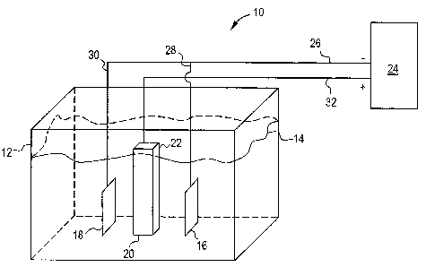
One embodiment includes an electrochemical stripping system to accelerate
removal of the coating from the substrate. FIG. 1 schematically illustrates
such a
system 10, which includes an electrolyte bath receptacle 12. The bath contains
electrolyte 14, e.g., an aqueous composition of HXAF6, along with one or more
of the
other additives described previously. The electrolyte bath receptacle 12 is
formed of
any suitable material which is non-reactive with any of the bath components.
The
shape and capacity of the receptacle 12 may vary according to the application,
as long
as the receptacle 12 is sized sufficiently to accommodate the electrodes and
electrolyte 14. The electrochemical stripping system of this invention
includes at least
one electrode. Two electrodes, 16 and 18, are depicted in FIG. 1. The number
of
electrodes will vary, depending on various factors, such as the size and shape
of the
article being treated. Each electrode, 16 and 18, is formed with an
appropriate
geometry that is configured to direct electrical fields to surfaces of a
coated article 20.
The electrodes 16 and 18 are generally non-consumable and remain intact
throughout
the electrochemical stripping process.
The article 20, which is to be stripped by the electrochemical stripping
system 10, is disposed in the receptacle 12. The article 20 is at least
partially covered
with one or more of the coatings described previously. The article 20 is
disposed
between the electrodes 16 and 18, and positioned so that an electric field can
be
established between the electrodes 16 and 18 and the selected coated surfaces
of the
-14-
CA 02611819 2007-11-22
213975
article 20. The electrolyte 14 is delivered to the receptacle 12 in amounts
sufficient to
submerge parts of the article 20 and electrodes 16 and 18. If a portion 22 of
the article
20, e.g., a dovetail section of a turbine component, does not require
stripping, this
portion may be kept above the level of the electrolyte 14. Alternatively, this
portion
22 can be physically masked so as to shield the electric field. A further
alternative is
to minimize the electric field over this portion 22, for example, by modifying
the
locations of electrodes 16 and 18. The portions 22 that are to be
electrochemically
stripped should be submerged in the electrolyte 14.
A power supply 24 establishes an electric field in the electrochemical
stripping system. The power supply 24 is usually direct current (DC), with a
switching-mode capability. It is often operated in the constant potential
mode. Power
supply 24 carries current over connections 26, 28 and 30, to the electrodes 16
and 18.
The electrodes 16 and 18 are connected to the negative terminals of the power
supply
24. The stripping of the coating from article 20 comprises the electrolyte 14
reacting
with the coating. The electrolyte 14 carries a charge to article 20, and under
the action
of the electric current, the coating is stripped from the article 20.
Various parameters define the stripping characteristics for this embodiment.
These parameters influence the rate of material removal and thus, the
efficiency of the
stripping process. Non-limiting, exemplary parameters are: electrode geometry,
power
supply voltage or current (dependent on parameters being controlled),
electrolyte
concentrations, solvent composition, use of agitation, processing time,
distance
between the article 20 and electrodes 16 and 18, and temperature of the
electrolyte 14.
Those who are familiar with electrochemical machining techniques would be
familiar
with many of the stripping parameters which relate to this embodiment.
The stripping parameters may vary over operational ranges. For example, a
DC power supply 24 voltage may vary from a trace voltage (the term "trace"
means a
small but measurable value) to about 30V. The electrical current is sometimes
pulsed,
to allow charged ionic byproducts to leave the electrode boundary layers.
However,
pulsed power application is not critical for this embodiment. The distance
between the
-15-
CA 02611819 2007-11-22
213975
article 20 and the electrodes 16 and 18 typically varies in a range from about
0.1 inch
(0.25 cm) to about 10 inches (25.4 cm).
The temperature of the electrolyte 14 can be maintained up to about 100 C.
In some embodiments, the temperature is maintained below about 50 C, and in
other
embodiments, the temperature range is from about 50 C. to about 30 C.
The stripping time (i.e., the immersion time within the electrolyte) may vary
considerably. Factors which influence the selection of an appropriate time
include the
composition of the coating being removed; as well as its microstructure,
density, and
thickness. The electrochemical stripping time may increase with higher density
and
thicker coatings. Usually, the time will range from about 1 minute to about 36
hours,
and in some cases, from about 5 minutes to about 8 hours. In some other
instances, the
immersion time is in the range of about 10 minutes to about 3 hours.
Usually, the substrate is a metallic material. As used herein, "metallic"
refers
to substrates which are primarily formed of metal or metal alloys, but which
may also
include some non-metallic components. Non-limiting examples of metallic
materials
are those which comprise at least one element selected from the group
consisting of
iron, cobalt, nickel, aluminum, chromium, titanium, and mixtures which include
any
of the foregoing (e.g., stainless steel).
Very often, the metallic material is a superalloy. Such materials are known
for high-temperature performance, in terms of tensile strength, creep
resistance,
oxidation resistance, and corrosion resistance. The superalloy is typically
nickel-,
cobalt-, or iron-based, although nickel- and cobalt-based alloys are favored
for high-
performance applications. The base element, typically nickel or cobalt, is the
single
greatest element in the superalloy by weight. Illustrative nickel-base
superalloys
include at least about 40 % Ni by weight, and at least one component from the
group
consisting of cobalt, chromium, aluminum, tungsten, molybdenum, titanium, and
iron.
Illustrative cobalt-base superalloys include at least about 30% Co by weight,
and at
least one component from the group consisting of nickel, chromium, tungsten,
molybdenum, tantalum, manganese, carbon, and iron.
-16-
CA 02611819 2007-11-22
213975
The actual configuration of a substrate may vary widely. As a general
illustration, the substrate may be in the form of a houseware item (e.g.,
cookware), or
a printed circuit board substrate. In many embodiments, superalloy substrates
are in
the form of a combustor liners, combustor domes, shrouds, or airfoils.
Airfoils,
including buckets or blades, and nozzles or vanes, are typical substrates that
are
stripped according to embodiments of the invention. The invention is useful
for
removing coatings from the flat areas of substrates, as well as from curved or
irregular
surfaces which may include indentations, hollow regions, or holes (e.g., film
cooling
holes).
While the invention has been described in detail in connection with only a
limited number of embodiments, it should be readily understood that the
invention is
not limited to such disclosed embodiments. Rather, the invention can be
modified to
incorporate any number of variations, alterations, substitutions or equivalent
arrangements not heretofore described, but which are commensurate with the
spirit
and scope of the invention. Additionally, while various embodiments of the
invention
have been described, it is to be understood that aspects of the invention may
include
only some of the described embodiments. Accordingly, the invention is not to
be seen
as limited by the foregoing description, but is only limited by the scope of
the
appended claims.
-17-