Note: Descriptions are shown in the official language in which they were submitted.
CA 02612068 2007-12-13
WO 2006/133913 PCT/EP2006/005699
1
Traction wire arrangement and adjustable support assembly using the traction
wire arrangement
The present invention relates to a traction wire arrangement and to an
adjustable support
assembly for a seat in which the traction wire arrangement is used for
adjusting the degree of
support provided by the support assembly. In particular, the present invention
relates to an
adjustable lumbar support assembly having a support member which is configured
as a wire
framework having two lateral side wires and a plurality of transverse wires
extending
between the two lateral side wires and providing load bearing support for
upholstery of a
seat, e.g. a vehicle seat.
Support assemblies of the afore-mentioned kind are well-known in the art and
may have
various configurations determined by the design of the seat in which the
support assembly is
to be mounted. A support assembly is for example known from GB 2 342 287 A.
The support
assembly described in this document comprises a wire framework having two
lateral side
wires which are suspendable in a seat frame and between which extend a
plurality of
transverse wires for providing load bearing support for upholstery of the
seat. The transverse
wires are attached to the lateral side wires by being wound around the latter
in the form of a
helix with an end portion of the respective transverse wires extending
substantially
perpendicular to the respective lateral side wires. Some of the transverse
wires extend
beyond the respective lateral side wire and terminate in free ends which can
be formed as
hook-like fingers for attachment to the seat frame, e.g. by providing eyes on
the seat frame
with which the hook-like fingers may be engaged. Other known attachment means
comprise
springs for coupling the support assembly to the seat frame.
Furthermore, it is known from EP 0 552 904 B1 to provide an adjusting
mechanism for a
support assembly. The support assembly disclosed in this document is attached
to a seat
frame via springs, and Bowden cable mechanisms are provided by means of which
the
support assembly can be pivoted at hinge points provided in the lateral side
wires. A further
mechanism without such hinges is known from US 5,988,745 A.
In order to adjust the degree of lumbar support, usually the support member or
a part thereof
is moved in a direction extending perpendicular to the support plane. The
support assembly
may be pivoted about a transversal axis, may be arched or may be moved as a
whole. In
each case, it is desirable that the support member is moved on both of its
lateral sides in a
CA 02612068 2007-12-13
WO 2006/133913 PCT/EP2006/005699
2
similar manner so that a symmetric lumbar support feeling is created. This is,
however,
difficult to achieve and typically requires two separate Bowden cable
arrangements.
Therefore, it is an object of the present invention to provide an improved
possibility for
simultaneously acting on the two sides of a support member, so that a
symmetric support
can be realized easily with only few components and at low cost.
This object is achieved by a traction wire arrangement for an adjustable
support assembly
according to independent claim 1. The dependent claims define preferred and
advantageous
embodiments of the present invention.
According to the invention, the traction wire arrangement comprises a Bowden
cable having
a wire and a sheath, a first traction wire, and a coupling device for coupling
the first traction
wire and the Bowden cable. The sheath of the Bowden cable is at one end
fixedly attached
to the coupling device. The first traction wire is at one end fixedly attached
to the coupling
device and extends from the coupling device in a first direction. The wire of
the Bowden
cable extends from the coupling device in a second direction which is
substantially opposite
to the first direction and forms a second traction wire.
In this arrangement, the length of the second traction wire extending from the
coupling
device can be shortened by means of the Bowden cable, for which purpose
preferably an
actuating mechanism is connected to the other end of the Bowden cable, i.e.
the end which
is not connected to the coupling device. Upon shortening the second traction
wire, a tensile
force is applied to the coupling device which therefore is moved in the second
direction. By
moving the coupling device in the second direction, in turn a tensile force is
transmitted via
the first traction wire, but with an opposite direction. Consequently, the
traction wire
arrangement allows for the application of a first tensile force with respect
to an end point of
the first traction wire and a second tensile force with respect to an end
point of the second
traction wire, using only a single Bowden cable and a single actuating
mechanism. The
tensile force is symmetrically divided between the two traction wires, which
makes the
traction wire arrangement in particular suitable for an adjustable support
assembly in which
the degree of support is adjusted by acting simultaneously on a first side and
a second side
of a support member. The traction wire arrangement has a simple structure and
can thus be
easily manufactured at low cost.
The coupling device preferably comprises guiding means for guiding the second
traction wire
into the second direction, i.e. into a direction opposite to that in which the
first traction wire
CA 02612068 2007-12-13
WO 2006/133913 PCT/EP2006/005699
3
extends. In this way, it is accomplished that the tensile forces transmitted
by the first traction
wire and the second traction wire can effectively be directed so as to act in
opposite
directions, thereby achieving an optimum utilisation of the power transmitted
via the Bowden
cable and avoiding sharp bendings of the traction wires.
According to a preferred embodiment, the guiding means for guiding the second
traction wire
are formed as a guiding hole extending through a body of the coupling device.
In this case,
the diameter of the guiding hole is preferably equal to or slightly larger
than that of the
second traction wire. The guiding hole may at one end thereof have a portion
having a
diameter substantially corresponding to that of the outer diameter of the
sheath of the
Bowden cable, whereby a receiving portion for the sheath of the Bowden cable
and a
shoulder are formed inside the guiding hole, the shoulder functioning as an
abutment for an
end face of the sheath of the Bowden cable. Therefore, both the guiding means
for the
second traction wire and attachment means for attaching the outer sheath of
the Bowden
cable may be formed in a simple manner by providing a single hole having two
different
diameters to the body of the coupling device. Different methods may be used
for fixing the
sheath of the Bowden cable to the coupling device, e.g. a force fit, gluing,
etc. In case that
the second traction wire is permanently held under tension it may even by
sufficient to simply
introduce the sheath of the Bowden cable into the receiving portion of the
hole where it is
held by the force acting on the Bowden cable.
Preferably, the traction wire arrangement also comprises attachment means for
fixedly
attaching the end of the first traction wire to the coupling device. The
attachment means may
comprise an attachment hole formed in the body of the coupling device, the
attachment hole
having a diameter equal to or slightly larger than that of the first traction
wire, and a nipple
formed at the end of the first traction wire and having a diameter which is
larger than that of
the attachment hole. In this arrangement, the nipple prevents the first
traction wire from
coming off the coupling device when a tensile force is transmitted. This
structure has the
advantage of being very simple and at the same time providing a reliable
attachment of the
first traction wire to the coupling device.
Preferably, the attachment hole further comprises a widened portion for
receiving the nipple
of the first traction wire. Moreover, a connection to an outer surface of the
body of the
coupling device is preferably formed over the entire length of the attachment
hole, the
connection allowing for the insertion of the first traction wire therethrough
into the attachment
hole. In a similar way, a connection may also be provided which allows for the
insertion of the
nipple connected to the end of the second traction wire. By this means, it is
possible to attach
CA 02612068 2007-12-13
WO 2006/133913 PCT/EP2006/005699
4
the first traction wire to the coupling device after the nipple has been
mounted on the end of
the first traction wire. Further, removal of the first traction wire from the
coupling device is
facilitated, e.g. for the purpose of maintenance or repair.
According to the present invention, a support assembly for a seat comprises a
support
member adapted to be incorporated into a seat frame, wherein the support
assembly is
adjustable by simultaneously acting on a first side of the support member and
on a second
side of the support member. The support assembly includes the traction wire
arrangement as
explained above, the first traction wire extending from the coupling device
towards the first
side of the support member and the second traction wire extending from the
coupling device
towards the second side of the support member. The first traction wire and the
second
traction wire are slidably held with respect to the support member. For this
purpose, the
support member preferably comprises holding means for slidably holding the
first traction
wire and the second traction wire with respect to the support member. The
other end of the
first traction wire is adapted to be connected to one side of the seat frame
and the end of the
second traction wire is adapted to be connected to the opposite side of the
seat frame, the
two sides of the seat frame being generally located in the vicinity of the
first side and the
second side of the support members, respectively.
In the support assembly as described above, a tensile force is simultaneously
transmitted via
the first traction wire and the second traction wire, which are slidably held
by the holding
means, to the support member. The length of the portions of the first traction
wire and of the
second traction wire extending from the support member and connecting to the
seat frame is
decreased in a symmetric fashion so that the support member is pulled towards
the seat
frame. Therefore, the degree of support provided by the support assembly can
be adjusted in
a desirable symmetric way.
Preferably, the other end of the traction wire and/or the end of the second
traction wire has a
shape to be hooked into the seat frame, e.g. by providing an end portion
having the shape of
a Z-nipple. In this way, mounting of the support assembly to the seat frame is
facilitated. The
holding means may be formed as two separate components to be connected to the
support
member at each side thereof, or may be formed as a single holding device
extending on the
support member along a transversal direction from the first side to the second
side. The latter
alternative may in particular be advantageous with respect to assembling the
support
assembly. Preferably, assembling is further facilitated by connecting the
holding means to
the support member by means of a clip mechanism, i.e. a clip portion provided
on the holding
means.
CA 02612068 2007-12-13
WO 2006/133913 PCT/EP2006/005699
In addition, it is preferred that guiding means are provided for guiding the
first traction wire
and/or the second traction wire in the portion between the holding means and
the attachment
point to the seat frame. In this region, the traction wires are subjected to a
high stress as the
5 forces are transmitted to the support member essentially at the holding
means. By providing
the guiding means, which preferably have a convexly curved guiding surface
along which the
wire runs, the load can be distributed and sharp bendings of the traction wire
are avoided.
Further, it is preferred that the coupling device of the traction cable
arrangement is slidably
connected to the support member so as to be movable along the transversal
direction.
According to a preferred embodiment, a single holding device is provided which
provides
both for the slidable connection of the coupling device and for the holding of
the first traction
wire and the second traction wire with respect to the support member. The
single holding
device is preferably formed as a plastic band extending across the support
member. For
providing the slidable connection of the coupling device, a slot may be formed
in the plastic
band for receiving a projection of the coupling device. The projection may
have a widened
portion having a width larger than that of the slot for holding the coupling
device with respect
to the plastic band. For facilitating the attachment of the coupling device to
the plastic band,
the slot may have a widened portion allowing for the widened portion of the
projection to be
inserted therethrough. Alternatively, guiding rails may be formed on the
plastic band, the
guiding rails extending along the transversal direction and being adapted to
receive a
corresponding lateral projection of the coupling device.
According to the present invention, the support member is preferably formed by
a wire
framework comprising two lateral side wires and transverse wires extending
between the
lateral side wires.
As can be seen from the above, the present invention allows for providing a
symmetric
support feeling by using only a single Bowden cable for adjusting the support
assembly. By
this means, the complexity of the assembly and the efforts in manufacturing
are kept at a low
level. Moreover, the traction wires can follow a smooth curve without any
sharp bendings,
thereby avoiding stresses and improving the durability.
In the following, preferred embodiments of the present invention will be
explained in detail
with reference to the accompanying drawings.
CA 02612068 2007-12-13
WO 2006/133913 PCT/EP2006/005699
6
Fig. 1 shows a perspective view of a lumbar support assembly according to an
embodiment
of the present invention,
Fig. 2 shows a perspective view illustrating a traction wire assembly
according to an
embodiment of the present invention,
Fig. 3A shows a cross-sectional view of the traction wire arrangement of Fig.
2,
Fig. 3B shows a cross-sectional view of a modification of the traction wire
arrangement of
Fig. 2,
Fig. 4 is a side view illustrating the operation of the support assembly of
Fig. 1,
Fig. 5 is a schematic illustration of a plate clip acting as a holding means
for slidably holding
a traction wire with respect to a support member of the support assembly of
Figs. 1 and 3,
Fig. 6 illustrates the process of mounting the plate clip on a wire framework
of the support
member,
Fig. 7 illustrates an alternative embodiment of the support assembly having a
plastic band
acting as a holding means for slidably holding the traction wires of the
support assembly with
respect to the wire framework of the support member,
Fig. 8 illustrates a slidable connection of a coupling device of the traction
wire arrangement
with respect to the holding means,
Fig. 9 illustrates an alternative arrangement for slidably holding the
coupling device on the
holding means, and
Fig. 10 illustrates an arrangement for slidably holding the coupling device on
the wire
framework of the support member.
In the following, the present invention will be explained with respect to an
adjustable lumbar
support assembly comprising a wire framework as a support member. The support
assembly
is configured to be incorporated into a backrest of a vehicle seat. However,
the concepts
explained hereinafter are also applicable to other types of support assemblies
using different
types of support members or providing the support in a different region.
CA 02612068 2007-12-13
WO 2006/133913 PCT/EP2006/005699
7
Fig. 1 shows a perspective view of a lumbar support assembly. The lumbar
support
assembly comprises a support member 20 essentially formed of a wire framework
having
two lateral side wires 4 and a plurality of transverse wires 7, 7'. The
transverse wires 7
extend between the lateral side wires 4, thereby forming a main portion of the
support
member 20. An additional transverse wire 7' is connected to the main portion
using flexible
connectors 8 having stripe-like portion extending along a longitudinal
direction, i.e. in parallel
to the lateral side wires 4. By means of the flexible connectors 8, the
support member 20 is
provided with a certain degree of flexibility so that the main portion can be
moved with
respect to the additional transverse wire 7'. The wire mat is formed of
separate wires which
are overmoulded with a plastic material. The lateral side wires 4 may actually
consist of
overmoulding material which joins the transverse wires 7 and has a
substantially round
cross-sectional shape.
The transverse wires 7, 7' generally extend between a first side and a second
side of the
support member 20 and are provided with undulations extending in a support
plane of the
support member 20. The undulations consist of an alternating series of
longitudinal and
transverse portions of the transverse wire 7, 7'. By means of the undulations,
the transverse
wires offer an increased support area for providing load bearing support for
upholstery or
cushioning of the seat. Further, the support member 20 becomes extendable
under a load
applied to the support assembly. The support member 20 as illustrated in Fig.
1 may also be
referred to as a suspension pad or a platform element.
As can be further seen from Fig. 1, some of the transverse wires 7, 7' have
end portions
extending laterally beyond the lateral side wires 4, thereby forming free end
portions 7a, 7b
which are generally used for attaching the support assembly to a seat frame
(not shown in
Fig. 1). The free end portions 7a are formed in a hook-like shape so that they
can be
engaged with a corresponding eye or hole in the seat frame. For providing
additional
flexibility, it is also possible to connect the end portions 7a to the seat
frame via tension
springs interposed between the seat frame and the end portions 7a. The tension
springs
could also be integrally formed with the end portions 7a of the transverse
wires 7, 7'.
The free end portions 7b of the lowermost transverse wire 7 are configured to
provide an
adjustable connection to the seat frame, allowing for an adjustment of the
degree of support
provided by the support assembly. The structure and operation of the adjusting
mechanism
will in the following be explained in more detail.
CA 02612068 2007-12-13
WO 2006/133913 PCT/EP2006/005699
8
As illustrated in Fig. 1, the adjusting mechanism comprises a traction wire
arrangement
essentially consisting of a Bowden cable 18, a first traction wire 17, a
second traction wire
19, and a coupling device 16 for coupling the Bowden cable 18 and the traction
wires 17, 19.
The traction wires 17, 19 extend from the coupling device 16 generally along
the transverse
direction and are slidably held on the support member 20 by plate clips 15
connected to the
end portions 7b of the lowermost transverse wire. In particular, the first
traction wire 17
extends from the coupling device 16 to the first side of the support member 20
where it is
slidably guided through the plate clip 15 and then terminates in a an end
portion 17a which
has the shape of a Z-nipple. By means of the Z-nipple, the end portion of the
first traction
wire 17 can be easily hooked into a corresponding receiving structure on the
seat frame, e.g.
an eye or a hole. In a similar manner, the second traction wire 19 extends
from the coupling
device 16 towards the second side of the support member 20 where it is
slidably guided
through the plate clip 15, and terminates in an end portion 19a having the
shape of a Z-
nipple for attaching the end portion 19a of the second traction wire to the
seat frame.
Accordingly, the support member is configured to be attached to opposite sides
of the seat
frame via the traction wires 17, 19. By simultaneously shortening portions of
the traction
wires 17, 19 extending from the support member 20, the support member can
therefore be
pulled towards the seat frame, thereby increasing the degree of lumbar
support. Similar as
with the end portions 7a, the end portions 17a, 19a of the traction wires 17,
19 can be
provided with an indirect connection to the seat frame via tension springs so
as to increase
the flexibility of the support assembly. Further, it is to be understood that
the adjustable
connection to the seat frame could also be provided at a different position,
e.g. in the middle
region of the support member 20.
In the following, the simultaneous shortening of the traction wires 17, 19
will be explained in
more detail. Fig. 2 shows a perspective view of the traction wire arrangement
comprising the
Bowden cable 18, the first traction wire 17, the second traction wire 19, and
the coupling
device 16. Fig. 3A shows a sectional view of the traction wire arrangement.
As illustrated, the coupling device 16 is essentially formed as a solid body
in which holes are
formed for attaching of guiding the first traction wire 17 and the second
traction wire 19. The
coupling device may be formed of a plastic material or of a metal. An
attachment hole 14 for
attaching the first traction wire 17 terminates at one end face of the
coupling device 16. A
guiding hole 12 for slidably guiding the second traction wire 19 terminates at
an opposite end
face of the coupling device 16. The attachment hole 14 and the guiding hole 12
have a
diameter equal to or slightly larger than the first traction wire 17 and the
second traction wire
19, respectively. The attachment hole 14 has an end portion inside the
coupling device which
CA 02612068 2007-12-13
WO 2006/133913 PCT/EP2006/005699
9
is widened so as to receive a nipple mounted on the end of the first traction
wire 17. A slot-
shaped connection to a side face of the coupling device 16 is formed along the
entire length
of the attachment hole 14, including the widened portion, thereby allowing for
the insertion of
the end of the first traction wire including the nipple into the attachment
hole 14. In this
arrangement, the first traction wire 17 can be assembled with the nipple and
then easily be
attached to the coupling device.
The guiding hole 12 for the second traction wire 19 extends from the end face
of the coupling
device 16 in an oblique direction through the body of the coupling device 16.
An entry to the
guiding hole 12 is formed in a side face of the coupling device 16. Starting
from the side face,
the guiding hole 12 comprises a widened portion having a diameter
substantially equal to the
outer diameter of the Bowden cable 18. At the end of the widened portion, an
annular
shoulder is formed inside the guiding hole which serves as an abutment for an
end face of
the sheath of the Bowden cable 18. The Bowden cable 18 is inserted into the
widened
portion of the guiding hole 12 in such a manner that the end face of the
sheath abuts on the
shoulder of the guiding hole 12. The wire of the Bowden cable 18 further
extends through the
guiding hole 12 and forms the second traction wire 19. The sheath of the
Bowden cable 18 is
held inside the widened portion of the guiding hole 12 by the tension applied
to the second
traction wire 19. In addition, the sheath of the Bowden cable 18 may be fixed
inside the
widened portion by means of a force fit or gluing.
As can be seen, in the traction wire arrangement as described above, the first
traction wire
17 is fixedly attached to the coupling device 16 and the second traction wire
19 is slidably
guided through the coupling device 16 and may be extended or retracted by
means of an
actuating mechanism connected to the other end of the Bowden cable 18. The
first traction
wire 17 and the second traction wire 19 extend from the coupling device 16 in
substantially
opposite directions, thereby allowing for oppositely directed tensile forces
to be transmitted
via the traction cable 17, 19. As the guiding hole 12 extends through the body
of the coupling
device 16 in an oblique direction, the second traction wire 19 can follow a
smooth curve and
sharp bendings of the second traction wire are avoided. This may be further
enhanced by
providing the guiding hole 12 with a suitable curvature. Alternatively, the
Bowden cable 18
could be inserted into the coupling device from the end face on which the
first traction wire
17 is attached, thereby allowing for the second traction wire 19 to extend
through the body of
the coupling device 16 along a straight line. Furthermore, a connection to an
outer surface of
the coupling device 16 could be provided also in case of the guiding hole 12
so as to allow
for the insertion of the second traction wire 19 therethrough.
CA 02612068 2007-12-13
WO 2006/133913 PCT/EP2006/005699
Fig. 3B illustrates a modification of the traction wire arrangement as shown
in Figs. 2 and 3A. =
The modified arrangement includes an additional compression spring 19c which
is inserted in
the guiding hole 12, between the sheath of the Bowden cable 18 and the
shoulder of the
guiding hole 12. The compression spring 19c provides for an increased
flexibility of the
5 traction wire arrangement.
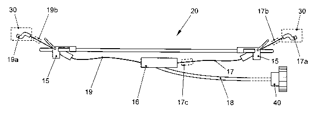
Fig. 4 shows a side view of the support assembly along the transverse
direction. As
illustrated, the support member 20 is connected to opposite sides of the seat
frame 30 by
means of the first traction wire 17 and the second traction wire 19. For this
purpose, the Z-
10 nipples of the traction wires are hooked into a corresponding receiving
structure on the seat
frame. In addition, tension springs 17b, 19b may be provided, as explained
above. The
tension springs 17b, 19b could also be integrally formed with the Z-nipples.
In addition, a
tension spring could be formed in the first traction wire 17 near the coupling
device, as
illustrated at 17c. The traction wires 17, 19 are slidably held on the support
member 20 by
means of the plate clips 15. The wire of the Bowden cable 18 which forms the
second
traction wire 19 extending from the coupling device 16 can be retraced or
extended using an
actuating mechanism 40. The actuating mechanism 40 is illustrated as a hand
wheel. It is to
be understood that also other types of actuating mechanism may be used, e.g.
an electrically
driven actuating mechanism.
The operation of the adjustable lumbar support assembly is as follows: By
means of the
actuating mechanism 40 the wire of the Bowden cable 18 is retracted inside the
sheath of the
Bowden cable. This causes the second traction wire 19 to be shortened. As a
result, the
second traction wire 19 is pulled-in through the plate clip 15 holding the
second traction wire
19, thereby reducing the length of the portion of the second traction wire 19
extending
between the plate clip 15 and the seat frame 30. In addition, the coupling
device 16 is pulled
by the second traction wire 19 or pushed by the sheath of the Bowden cable 18
towards the
plate clip 15 holding the second traction wire 19, i.e. to the left side in
the illustration of Fig. 4.
This in turn causes the first traction wire 17, which is fixedly connected to
the coupling device
16, to be pulled-in through the plate clip 15 holding the first traction wire
17, thereby reducing
the length of the portion of the first traction wire extending between the
plate clip 15 and the
seat frame 30. As the first traction wire 17 and the second traction wire 19
extend from the
coupling device 16 into opposite directions, tensile forces are transmitted
via the traction
wires 17, 19 which have equal magnitudes, but opposite directions. This causes
the length of
the portions of the traction wires 17, 19 extending between the plate clips 15
and the seat
frame 30 to be reduced by the same amount, resulting in a symmetric
displacement of the
support member 20 towards the seat frame 30. Actuating the Bowden cable in the
opposite
CA 02612068 2007-12-13
WO 2006/133913 PCT/EP2006/005699
11
direction, i.e. extending the second traction wire 19 from the coupling device
16, causes an
opposite movement of the support member.
Fig. 5 shows a more detailed illustration of the plate clip 15 holding the
first traction wire 17
on the support member 20. The plate clip 15 for holding the second traction
wire 19 on the
support member 20 is configured in a similar way. As can be seen from Fig. 5,
the plate clip
comprises a guiding portion 15a through which the traction wire 17 is guided.
The guiding
portion 15a is formed as a tubular portion through which a guiding hole is
formed. In addition,
a guiding member 15b is provided which extends from the plate clip 15 towards
the seat
10 frame and has a convexly curved guiding surface along which the traction
wire 17 is guided.
The guiding portion 15a and the guiding member 15b are arranged in such a
manner that the
traction wire 17, which arrives at the plate clip 15 in an essentially
transverse direction, is
smoothly redirected towards the seat frame. By this means, the load
transmitted from the
traction wire 17 to the support member via the plate clip 15 is distributed
and sharp bendings
15 of the traction wire 17 are avoided, thereby increasing the durability of
the support assembly.
The plate clip 15 further comprises a clip portion 15c and a receiving hole
15d which serve
for the connection of the plate clip 15 to the wire 7 of the support member.
The plate clip 15
is preferably formed of a plastic material.
Fig. 6 illustrates the process of attaching the plate clip 15 to the end
portion 7b of the
transverse wire 7. In a first step, which is illustrated in Fig. 6a), the
plate clip 15 is slipped on
the longitudinal end portion of the wire 7 in such a manner that the wire is
received inside the
receiving hole 15d of the plate clip 15. When the clip portion 15c of the
plate clip 15 comes
into alignment with a transverse portion extending from the longitudinal end
portion of the
wire 7, the plate clip 15 is rotated about the pivot axis formed by the
longitudinal end portion
of the wire 7 so that the transverse portion of the wire 7 is received inside
the clip portion 15c
of the plate clip 15, as illustrated in Fig. 6b). The final state of the plate
clip 15 mounted on
the transverse wire 7 is shown in Fig. 6c).
Fig. 7 shows an alternative arrangement for slidably holding the traction
wires 17, 19 on the
support member 20. The support member 20 generally has the same structure as
explained
above with respect to Fig. 1. However, instead of the plate clips 15, a
plastic-band holding
device 45 is used as a holding means for slidably holding the traction wires
17, 19 on the
support member 20. The plastic-band holding device 45 constitutes a single
holding device
extending from one side of the support member 20 to the opposite side thereof.
The holding
device has guiding portions 46 formed thereon. The traction wires 17, 19 pass
through the
CA 02612068 2007-12-13
WO 2006/133913 PCT/EP2006/005699
12
guiding portions 46 and are thereby slidably held with respect to the support
member 20. The
plastic-band holding device 45 is preferably secured to the support member 20
by means of
clip portions similar to that formed on the plate clips 15.
In a central portion of the plastic-band holding device 45, connecting means
are provided for
slidably holding the coupling device 16 on the plastic-band holding device 45.
The
connecting means comprise a slot provided in the plastic-band holding device
45. The slot 48
extends in the transverse direction and is configured to receive therein a
projection extending
from the coupling device 16. The slot 48 comprises a widened portion 48a which
allows for
the insertion of the projection of the coupling device 16 when assembling the
support
member 20 with the traction wire arrangement. In the structure according to
Fig. 7, undesired
movements of the coupling device 16 in the longitudinal direction or away from
the support
member 20 are prevented, thereby resulting in a more effective conversion of
the force
applied to the Bowden cable to the tensile forces transmitted via the traction
wires 17, 19.
Further, the load which is applied to the support member 20 when shortening
the traction
wires 17, 19 is distributed over a large area, thereby improving the
durability of the support
assembly. In this respect, is should be noted that the plastic-band holding
device 45
comprises curved end portions 45b which function as guiding members for the
traction wires
17, 19, similar to the guiding members 15b of the plate clips. By this means,
sharp bendings
of the traction wires 17, 19 are avoided and the durability is further
improved.
Fig. 8 is a sectional view further illustrating the slidable connection of the
coupling device 16
to the plastic-band holding device 45. As illustrated, the coupling device 16
comprises a
projection 16a configured to be slidably received in the slot 48 of the
plastic-band holding
device 45. The projection 16a has a width which is equal to or slightly
smaller than the width
of the slot 48. A widened portion 16b is formed at the end of the projection
16a and engages
the plastic-band holding device 45 on a side facing away from the coupling
device 16. By this
means, the coupling device 16 is securely held on the plastic-band holding
device 45. The
widened portion 48a of the slot 48 is configured with a size and shape which
is suitable for
allowing the widened portion 16b of the projection 16a to be inserted
therethrough.
Fig. 9 shows an alternative arrangement for slidably holding the coupling
device 16 on the
plastic-band holding device 45. In this case, guide rails 49 are formed along
the transversal
direction. The coupling device 16 comprises lateral projections 16c which are
configured to
be received within an interior portion of the guide rails 49. Also in this
arrangement,
undesired movements of the coupling device 16 in the longitudinal direction or
in a direction
away from the support member 20 are prevented.
CA 02612068 2007-12-13
WO 2006/133913 PCT/EP2006/005699
13
Fig. 10 shows an arrangement for slidably holding the coupling device 16
directly on the wire
framework of the support member 20. For this purpose, the coupling device 16
comprises
receiving portions 16d. The receiving portions 16d are configured to receive
therein a
longitudinal portion of one of the transverse wires 7. As illustrated, the
receiving portions 16d
each enclose the portion of the transverse wire 7 from three sides and have an
elongated
shape which allows for displacing the transverse wire 7 inside the receiving
portion 16d. In
Fig. 10, the receiving portions 16d are configured as U-shaped grooves with
their respective
open sides facing towards each other. Alternatively, the open sides of the U-
shaped grooves
could be facing away from each other. The closed sides of the grooves serve as
an abutment
for the transverse wire 7 when the coupling device is displaced in the
transversal direction
and thereby limit the total range of movement. Displacement of the coupling
device 16 away
from the support member is avoided.
In the foregoing, the lumbar support assembly has been described as comprising
a support
member 20 which is formed of a wire framework. Alternatively, a different type
of support
member may be used, e.g. a plate member. Depending on the configuration of the
support
member, it may be advantageous to form means for holding and guiding the
traction wires
17, 19 with respect to the support member directly on the support member, i.e.
integrally
therewith. In this case, the functions of the plate clips or of the plastic-
band holding device
could be integrated into the support member.