Language selection

Search

Patent 2612100 Summary

Third-party information liability

Some of the information on this Web page has been provided by external sources. The Government of Canada is not responsible for the accuracy, reliability or currency of the information supplied by external sources. Users wishing to rely upon this information should consult directly with the source of the information. Content provided by external sources is not subject to official languages, privacy and accessibility requirements.

Claims and Abstract availability

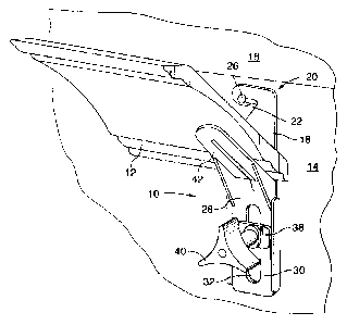
Any discrepancies in the text and image of the Claims and Abstract are due to differing posting times. Text of the Claims and Abstract are posted:

  • At the time the application is open to public inspection;
  • At the time of issue of the patent (grant).
(12) Patent: (11) CA 2612100
(54) English Title: TOOL FOR POSITIONING MOLDING
(54) French Title: OUTIL DE POSITIONNEMENT DE MOULURE
Status: Granted and Issued
Bibliographic Data
(51) International Patent Classification (IPC):
  • E04F 21/00 (2006.01)
  • B25B 11/00 (2006.01)
(72) Inventors :
  • SMITH, PATRICK J. (Canada)
(73) Owners :
  • SMITHWORKS INC.
(71) Applicants :
  • SMITHWORKS INC. (Canada)
(74) Agent: SMART & BIGGAR LP
(74) Associate agent:
(45) Issued: 2015-02-24
(22) Filed Date: 2007-11-23
(41) Open to Public Inspection: 2008-06-08
Examination requested: 2012-11-02
Availability of licence: N/A
Dedicated to the Public: N/A
(25) Language of filing: English

Patent Cooperation Treaty (PCT): No

(30) Application Priority Data:
Application No. Country/Territory Date
60/869,134 (United States of America) 2006-12-08

Abstracts

English Abstract

A tool for positioning molding, such as crown molding, during installation, has a base member adapted to be releasably hung on a wall near the ceiling. A retaining member is vertically slidably mounted on the base member and has an upper end portion disposed at an acute angle to hold a piece of molding at a desired attitude between the retaining member and the wall. The retaining member is slid and locked in vertically and locked in position to hold the molding in place while it is fastened to the wall, after which the tool is removed from the wall.


French Abstract

Un outil de positionnement de moulure, comme une moulure couronnée, pendant son installation, possède un élément de base adapté pour être suspendu de manière amovible sur un mur près du plafond. Un élément de retenue est monté verticalement de manière coulissante sur lélément de base et possède une partie dextrémité supérieure à un angle aigu pour maintenir une pièce de moulure à une position souhaitée entre lélément de retenue et le mur. Lélément de retenue est glissé et verrouillé verticalement et verrouillé en position pour maintenir la moulure en place tandis quelle est fixée au mur, après quoi loutil est retiré du mur.

Claims

Note: Claims are shown in the official language in which they were submitted.

CLAIMS:
1. A tool for positioning molding during installation of the molding, the
tool
comprising:
a base member having means for releasably hanging the base member
on a vertical surface;
a retaining member slidably mounted on the base member for vertical
movement relative to the base member, the retaining member having
an upper end portion disposed at an acute angle to the base member
to hold a piece of molding in a desired attitude between the retaining
member and the vertical surface; and
means for releasably locking the retaining member in position relative
to the base member,
wherein the means for hanging the base member is means defining a slot
extending inwardly and upwardly from the periphery of the base member to
the vertical centerline of the base member.
2. A tool as claimed in claim 1 wherein the retaining member upper end
portion
is disposed at a fixed angle relative to the base member.
3. A tool as claimed in claim 2 wherein the fixed angle is 45 degrees.
6

4. A tool as claimed in claim 1 wherein the retaining member upper end
portion
is pivotally mounted in the retaining member to vary said acute angle, and
further comprising means for releasably locking the upper end portion at a
desired acute angle in the retaining member.
5. A tool as claimed in claim 1 wherein the means for releasably locking
the
retaining member in position is a threaded fastener.
6. A tool for positioning molding during installation of the molding on a
vertical
surface, the tool comprising:
a base member adapted to be releasably hung on said vertical surface;
a retaining member slidably mounted on the base member for vertical
movement relative to the base member, the retaining member having an
upper end portion disposed at an acute angle to the base member to hold a
piece of said molding in a desired attitude between the retaining member and
said vertical surface; and
an arrangement for releasably locking the retaining member in position
relative to the base member.
wherein the base member is adapted to be releasably hung on said vertical
surface by a slot extending inwardly and upwardly from the periphery of the
base member to the vertical centerline of the base member.
7

7. A tool according to claim 6, wherein the retaining member upper end
portion
is pivotable to vary said acute angle and releasably lockable to set a desired
acute angle
8. A tool according to claim 6, wherein the arrangement for releasably
locking
the retaining member in position relative to the base member comprises a
slot defined in the retaining member and a threaded fastener which extends
through the base member and through the slot.
8

Description

Note: Descriptions are shown in the official language in which they were submitted.


CA 02612100 2007-11-23
TOOL FOR POSITIONING MOLDING
FIELD OF THE INVENTION
[0001] This invention relates to non-powered constructions tools, and in
particular, to tools for mounting moldings, such as crown moldings.
BACKGROUND OF THE INVENTION
[0002] In the construction industry, it is often desired to install trim or
moldings
horizontally on a wall or other vertical surface. Usually this is a two man
job,
because it takes one person to hold the molding in position while the other
person
attaches or fastens it to the wall. The difficulty with this is that it is
labour intensive
and thus costly to do.
SUMMARY OF THE INVENTION
[0003] The tool of the present invention allows one person to install
horizontal
strips, such as trim or molding, on a vertical surface. The tool has a base
member
that is releasably attached to the vertical surface. A retaining member is
slidably
mounted on the base member for vertical movement and has an upper end portion
disposed at an acute angle to hold the horizontal strip at a desired attitude.
Releasable locking means allows the retaining member and thus the horizontal
strip
to be slid vertically into position and held there while the strip is attached
to the
vertical surface.
[0004] According to the invention, there is provided a tool for positioning
molding, such as crown molding, during installation of the molding. The tool
comprises a base member having means for releasably hanging the base member
1

CA 02612100 2007-11-23
on a vertical surface. A retaining member is slidably mounted on the base
member
for vertical movement relative to the base member. The retaining member has an
upper end portion disposed at an acute angle to the base member to hold a
piece of
molding in a desired attitude between the retaining member and the vertical
surface. Also, means are provided for releasably locking the retaining member
in
position relative to the base member.
BRIEF DESCRIPTION OF THE DRAWINGS
[0005] Preferred embodiments of the invention will now be described, by way of
example, with reference to the accompanying drawings, in which:
[0006] Figure 1 is a perspective view of a preferred embodiment of a tool
according to the present invention shown holding a piece of molding in
position
ready to be installed;
[0007] Figure 2 is a perspective view similar to Figure 1 but without the
piece of
molding; and
[0008] Figure 3 is an exploded perspective view of the tool shown in Figures 1
and 2.
DESCRIPTION OF THE PREFERRED EMBODIMENTS
[0009] Referring to the drawings, a preferred embodiment of a tool for
mounting horizontally a strip of material, such as trim or molding, is
generally
indicated in the drawings by reference numeral 10. In Figure 1, the horizontal
strip
of material is a piece of crown molding 12, but it could be any other type of
strip
2

CA 02612100 2007-11-23
material desired to be attached to a vertical surface 14, such a wall, or an
adjacent
horizontal surface 16, such as a ceiling, located above the vertical surface
14.
[0010] Tool 10 includes a generally flat base member 18 having an upper end
portion 20 which defines a slot 22 extending inwardly and upwardly from the
periphery of base member 18 to the vertical centre line 24 of base member 18,
so
that tool 10 may be releasably attached to vertical surface 14 by being hung
on a
nail 26 with the tool 10 hanging vertically from nail 26. It will be
appreciated that
tool 10 may be removed from vertical surface 14 by being slid upwardly and
horizontally off nail 26.
[0011] Tool 10 also includes a retaining member 28 having a lower portion 30
defining a slot 32. Base member 18 has a central boss 34 (see Figure 3) that
is
located in slot 32, so that retaining member 28 may be slidably mounted on
base
member 18 for vertical sliding movement relative to base member 18. A bolt 36
passes through boss 34 and slot 32, and through a washer 38 to be threaded
into a
knob 40. By turning knob 40, retaining member 28 is releasably locked in
position
relative to base member 18. The bolt 36 and threaded knob 40 constitute a
threaded fastener and are means for releasably locking the retaining member 28
in
position relative to the base member 18.
[0012] Retaining member 28 also has an upper end portion 42 disposed at an
acute angle relative to base member 18 and thus also to vertical surface 14.
The
size of this acute angle is chosen to suit the type of strip or molding 12
desired to
be installed using tool 10. Where molding 12 is crown molding which is
designed to
be installed at an angle of 45 to the wall and ceiling, the acute angle would
be
roughly 45 , or such that the crown molding 12 is held at the desired attitude
or
45 angle between retaining member 28 and base member 18 or vertical surface
14. For other types of molding, such as cove molding, the acute angle could be
30
or 60 or whatever makes the molding sit at the desired attitude for
installation.
3

CA 02612100 2007-11-23
[0013] Although upper end portion 42 is shown in the drawings disposed at a
fixed angle relative to the base member lower portion 30, the retaining member
upper end portion 42 could be pivotally mounted in the retaining member 28
where
upper portion 42 meets lower portion 30, so that the acute angle could be
adjusted
or varied to suit the molding being installed. In this case, another threaded
fastener or other locking means would be used for releasably locking the upper
end
portion 42 at the desired acute angle in retaining member 28.
[0014] In use, usually a pair of tools 10 are used to install a piece of
molding
12, one tool 10 being located near each end of the piece of molding. Nails 26,
or
screws if preferred, are partially driven into vertical surface 14 near the
ceiling or
horizontal surface 16. The tools 10 are then hung on nails 26. Threaded
fasteners
36, 40 are then backed off or released and retaining members 28 are slid
downwardly into a lower position and the piece of molding is then suspended in
position on the two tools 10 resting on the inclined upper end portions 42 of
retaining members 28. The retaining members 28 are then slid upwardly until
the
molding 12 engages ceiling 16. Knobs 40 are then tightened to hold the molding
in
this position, and the molding is then fastened to the wall 14 or ceiling 16,
or both,
using nails or screws as desired. After the molding 12 is nailed or screwed
into
place, knobs 40 are backed off or unscrewed to release retaining members 28
allowing them to be slid downwardly to the lowermost position. The base
members
18 can then be slid upwardly and to the side off nails 26 and tools 10 slipped
downwardly out from beneath molding 12. Additional fasteners can then be used
to
further attach the molding to the wall 14 or ceiling 16 if so desired.
[0015] Having described preferred embodiments of the invention, it will be
appreciated that various modifications may be made to the structures described
above. For example, instead of the base member upper end portion 20 extending
above retaining member 28, base member 18 could be made shorter, or retaining
4

CA 02612100 2007-11-23
member lower portion 30 made longer, so that retaining member upper end
portion
42 extends above the upper end portion 20 of base member 18. In this
configuration, base member 18 would probably be positioned lower on vertical
surface 14, and if retaining member 28 was required to be slid upwardly over
nail
26, retaining member 28 or base member 18 would be modified to provide
clearance for nail 26. Molding 12 would then be held directly in contact with
wall 14
and ceiling 16.
[0016] Retaining member 28 could be locked in position on base member 18 in
other ways than using bolt 36 and knob 40. Although tool 10 is preferably made
out of metal, it could be made out of a suitable plastic or other material
that is
strong enough.
[0017] From the foregoing, it will be evident to persons of ordinary skill in
the
art that the scope of the present invention is limited only by the
accompanying
claims, purposely construed.

Representative Drawing
A single figure which represents the drawing illustrating the invention.
Administrative Status

2024-08-01:As part of the Next Generation Patents (NGP) transition, the Canadian Patents Database (CPD) now contains a more detailed Event History, which replicates the Event Log of our new back-office solution.

Please note that "Inactive:" events refers to events no longer in use in our new back-office solution.

For a clearer understanding of the status of the application/patent presented on this page, the site Disclaimer , as well as the definitions for Patent , Event History , Maintenance Fee  and Payment History  should be consulted.

Event History

Description Date
Common Representative Appointed 2019-10-30
Change of Address or Method of Correspondence Request Received 2018-01-12
Grant by Issuance 2015-02-24
Inactive: Cover page published 2015-02-23
Inactive: Final fee received 2014-12-10
Pre-grant 2014-12-10
Notice of Allowance is Issued 2014-09-02
Letter Sent 2014-09-02
Notice of Allowance is Issued 2014-09-02
Inactive: Approved for allowance (AFA) 2014-07-29
Inactive: Q2 passed 2014-07-29
Amendment Received - Voluntary Amendment 2014-07-07
Inactive: S.30(2) Rules - Examiner requisition 2014-04-07
Inactive: Report - No QC 2014-03-26
Amendment Received - Voluntary Amendment 2014-02-26
Inactive: S.30(2) Rules - Examiner requisition 2014-01-08
Inactive: Report - No QC 2013-12-31
Letter Sent 2012-11-26
Reinstatement Requirements Deemed Compliant for All Abandonment Reasons 2012-11-26
Deemed Abandoned - Failure to Respond to Maintenance Fee Notice 2012-11-23
Letter Sent 2012-11-15
All Requirements for Examination Determined Compliant 2012-11-02
Request for Examination Requirements Determined Compliant 2012-11-02
Request for Examination Received 2012-11-02
Inactive: Cover page published 2008-06-08
Application Published (Open to Public Inspection) 2008-06-08
Inactive: IPC assigned 2008-05-22
Inactive: First IPC assigned 2008-05-22
Inactive: IPC assigned 2008-05-22
Inactive: Filing certificate - No RFE (English) 2008-01-10
Filing Requirements Determined Compliant 2008-01-10
Application Received - Regular National 2008-01-10

Abandonment History

Abandonment Date Reason Reinstatement Date
2012-11-23

Maintenance Fee

The last payment was received on 2014-11-17

Note : If the full payment has not been received on or before the date indicated, a further fee may be required which may be one of the following

  • the reinstatement fee;
  • the late payment fee; or
  • additional fee to reverse deemed expiry.

Patent fees are adjusted on the 1st of January every year. The amounts above are the current amounts if received by December 31 of the current year.
Please refer to the CIPO Patent Fees web page to see all current fee amounts.

Owners on Record

Note: Records showing the ownership history in alphabetical order.

Current Owners on Record
SMITHWORKS INC.
Past Owners on Record
PATRICK J. SMITH
Past Owners that do not appear in the "Owners on Record" listing will appear in other documentation within the application.
Documents

To view selected files, please enter reCAPTCHA code :


To view images, click a link in the Document Description column. To download the documents, select one or more checkboxes in the first column and then click the "Download Selected in PDF format (Zip Archive)" or the "Download Selected as Single PDF" button.

List of published and non-published patent-specific documents on the CPD .

If you have any difficulty accessing content, you can call the Client Service Centre at 1-866-997-1936 or send them an e-mail at CIPO Client Service Centre.


Document
Description 
Date
(yyyy-mm-dd) 
Number of pages   Size of Image (KB) 
Description 2007-11-22 5 179
Abstract 2007-11-22 1 14
Drawings 2007-11-22 3 53
Claims 2007-11-22 2 64
Representative drawing 2008-05-13 1 11
Claims 2014-02-25 3 64
Claims 2014-07-06 3 61
Representative drawing 2015-02-03 1 11
Filing Certificate (English) 2008-01-09 1 159
Reminder of maintenance fee due 2009-07-26 1 110
Reminder - Request for Examination 2012-07-23 1 125
Acknowledgement of Request for Examination 2012-11-14 1 175
Courtesy - Abandonment Letter (Maintenance Fee) 2012-11-25 1 173
Notice of Reinstatement 2012-11-25 1 164
Commissioner's Notice - Application Found Allowable 2014-09-01 1 161
Fees 2009-08-09 1 36
Fees 2010-11-03 1 35
Correspondence 2014-12-09 1 51