Note: Descriptions are shown in the official language in which they were submitted.
ak 02612414 2013-07-29
- I -
Set of Paving Stones
DESCRIPTION
The invention relates to a set of concrete.
The object of the invention is to create a set of pavers
which is designed so as to be especially diversified.
According to one aspect of the invention there is provided a
set of concrete pavers, comprising substantially rectangular
pavers of uniform height with vertical side faces, a number
of pavers of uniform or different lengths and widths being
arranged in a row, and, in particular for forming a
rectangular or square laying bundle that can be picked up by
machine, comprising a number of parallel, adjacent rows of
pavers, continuous linear joints being formed in the end-
paver region of the rows of pavers when the sets are laid
together or, optionally, substantially meandering joints
being obtainable by interchanging row-end pavers, which are
of different lengths and are in close proximity, from
neighbouring sets, at least one section of the upper
delimiting surface of the pavers is convexly cambered toward
the outside and projections on the base parts of the pavers
are spaced apart on the side faces of said base parts, the
projections forming support elements for the adjacent pavers
and, in combination with projections on adjacent pavers,
creating spaces that act as water-drainage openings in the
joint regions,
characterized in that the set comprises not only
paving stones as pavers, with a length-to-height ratio
of less than or equal to 4, but also at least one paving slab
with a length-to-height ratio greater than 4.
ak 02612414 2013-07-29
- la -
According to one embodiment of the invention the set as
described herein may be characterized in that the paving
stones and slabs are dimensionally adapted to one another in
such a way that at least one joint beside a slab passes over
into at least one joint beside an adjacent paving stone.
According to a further embodiment the set as described herein
may be characterized in that the paving stones and slabs are
dimensionally adapted to one another in such a way that at
least one joint beside a paving stone ends at the edge of an
adjacent slab.
The set as described herein can be characterized in that the
paving stones and slabs are dimensionally adapted to one
another in such a way that the set has at least one
continuous joint beside paving stones and slabs.
The set as described herein may be characterized in that the
paving stones and slabs have projections which form the
support elements between paving stones and slabs.
The set as described herein can be characterized in that the
projections of the paving stones are made thicker and the
projections of the slabs thinner.
The set as described herein may be characterized in that the
paving stones have projections in which each projection forms
a support element for a corresponding projection of an
adjacent paving stone or an adjacent slab.
The set as described herein can be characterized in that the
edges of paving stones and adjacent slabs have different
heights. The set as described herein may be characterized in
that the edge of a paving stone is higher than the edge of an
adjacent slab. The set as described herein can be
ak 02612414 2013-07-29
- lb -
characterized in that the edges of adjacent paving stones
have different heights.
According to a further aspect of the invention there is
provided a set comprising a plurality of pavers, each paver
of the plurality of pavers being substantially rectangular,
having an upper delimiting surface, having vertical side
faces, and having a plurality of projections disposed spaced
apart on the vertical side faces, the plurality of
projections forming support elements for adjacent pavers of
the plurality of pavers and creating a respective interspace
between the respective paver and the adjacent pavers, wherein
at least a part-region of the upper delimiting surface
cambers outwards, and wherein the plurality of pavers is
arranged in at least first and second rows of pavers, the
first row of pavers being arranged side-by-side and parallel
to the second row of pavers;
wherein each of the first row of pavers and the second
row of pavers comprises:
respective first, second, third, and fourth paving block
rows arranged side by side in parallel, each of the first,
second, third, and fourth paving block rows comprising a
respective plurality of paving blocks of the plurality of
pavers, the paving blocks of each of the first, second,
third, and fourth paving block rows being adjacent side-by-
side, respectively, and each paving block of each plurality
of paving blocks having a length-to-height ratio less than or
equal to four; and
respective first and second slabs of the plurality of
pavers, the respective first and second slabs being adjacent
to paving blocks of each of the first, second, third, and
fourth. paving block rows, and each of the respective first
and second slabs, respectively, having a length-to-height
ratio greater than four;
wherein the first and second rows of pavers form in
respective first and second adjoining regions of the first
Mk 02612414 2013-07-29
- lc -
and second slabs, respectively, and the plurality of paving
blocks a first joint and a second joint, respectively, are a
linearly-continuous joint or a substantially-meandering
joint; and
wherein a respective cumulative width of the respective
first, second, third, and fourth rows of each of the first
rows of pavers and the second rows of pavers is equal to a
width of each of the respective first slab and the respective
second slab.
The set of concrete pavers according to the invention consists,
among other things, of pavers which form rectangular or square
laying bundles that can be picked up by machine which can be
combined quite easily and, if necessary, also be laid mechanically
and economically.
The set according to the invention thereby comprises paving stones
as pavers and slabs as pavers. According to the standard EN
1339:2003 (D) Point 3.2, a concrete slab is described as a
prefabricated concrete product whose overall length divided by its
thickness (height) is greater than the number 4. In
contrast
thereto, according to this standard, "paving stone" refers to
pavers which have a considerably smaller surface in comparison to
their height and, in particular, have a length-to-height ratio that
is less than or equal to the number 4.
In an advantageous embodiment, the set comprises paving stones
having a length-to-height ratio that is less than the number 3 and
slabs as pavers having a length-to-height ratio that is greater
Mk 02612414 2013-07-29
- 2 -
than the number 5.
On the whole, an especially diversified set is obtained by the
combination of slabs that have a relatively large surface with
paving stones that have a relatively small surface, in particular,
in association with the advantageous embodiment.
According to an advantageous embodiment, the paving stones
and slabs are dimensionally adapted to one another in such a
way that at least one joint beside a slab passes into at
least one joint beside an adjacent paving stone.
In this way, the set has joints which continue without interruption
beside paving stones and adjacent slabs. As a result, the laying
bundles formed can be quite easily picked up by machine and a
modular combination of different laying bundles can be produced
without excess length of corner stones and thus without further
finishing work.
According to a further advantageous embodiment, the paving stones
and slabs are dimensionally adapted to one another in such a way
that at least one joint beside a paving stone ends on the edge of
an adjacent slab.
As a result, on the one hand, an optically diversified overall
impression is obtained; on the other hand, due to its T-shaped
design, the joint, which is used as a water-drainage opening,
serves as a guiding water conduit which channels falling rainwater
or water from melting snow and ice and diverts it in a directed
manner from the paving stones to the adjacent slab edge. It is
thereby avoided that diverted water overflows onto the surface of
the slabs, as a result of which the danger of sliding or skidding
would occur for people or vehicles due to film or ice formation.
CA 02612414 2007-12-17
- 3 -
According to a further advantageous embodiment, the paving stones
and slabs are dimensionally adapted to one another in such a way
that the set has at least one continuous joint beside paving stones
and adjacent slabs.
As a result, falling water that is to be removed can be diverted
via a considerable longitudinal conduit parallel to adjacent paving
stones and slabs. Water that is to be removed is preventing from
striking the surface of the slabs or paving stones and,
consequently, perhaps affect road safety for people and vehicles
using it.
According to a further advantageous embodiment, the paving stones
and slabs have projections which form supports between adjacent
paving stones and slabs. As a result, a mutual support of paving
stones and slabs is also obtained when paving stones and adjacent
slabs meet.
Due to their rather large surfaces, the slabs thereby ideally serve
to support several adjacent adjoining paving stones. As a result,
the laying stability and secure positioning of the laid set is also
ensured in the paving stones and slabs under great stress and
introduction of forces by the users and vehicles.
According to a further advantageous embodiment, the projections of
the paving stones are thicker and the projections of the slabs are
thinner. As a result, it is attained that the joint distance
between a slab and an adjacent paving stone is somewhat greater
than the joint ddistance between adjacent slabs. As a result of
the enlarged joint between paving stone and slab, an improved water
drainage can be obtained if water to be diverted is purposefully
prevented from overflowing onto the slab due to the enlarged joint.
CA 02612414 2007-12-17
- 4 -
According to a further embodiment, individual or several paving
stones have projections in which each projection forms a support
element for a corresponding projection of an adjacent paving stone
or an adjacent slab.
A paving stone configured in this way is supported over its entire
lateral peripheral surface with its projections by corresponding
projections of the adjacent paving stones and slabs and can thus be
especially secured in its position when forces are introduced into
the paving stones.
According to a further embodiment, the edges of adjacent paving
stones and slabs have different heights. In particular with edges
that slope in comparison to the middle regions of the paving stones
and slabs (whether due to a camber or chamfer), a directed water
drainage takes place in the region of the edges of the paving
stones and slabs.
By designing paving stones and slabs with edges of different
heights, a water drainage can be channelled within the set. Thus,
for example, when designing paving stones with edges of a slighter
height, a type of "channel-like character" of the paving stones can
be produced in comparison to the adjacent slabs.
The paving stones thereby form a somewhat recessed channel and
carry falling water off, e.g. when there is an incline and slope.
In this way, the paving stones within the set receive a recessed
channel character and thereby give the set the characteristic of a
directed water drainage.
By purposefully designing the heights of the edges of the paving
stones and adjacent slabs, it can be determined whether the plane
of the paving stones should be recessed vis-à-vis the plane of the
CA 02612414 2007-12-17
- 5 -
slabs or the plane of the slabs recessed vis-à-vis the plane of the
paving stones. In this way, channels can be produced in the region
of the paving stones or slabs and the water drainage can
consequently be channelled and directed, in particular, with a
slight inclination of the surface of the paving stones.
The invention is described further with reference to an embodiment
in the drawings, showing:
Fig. 1 a set in a first embodiment,
Fig. 2 a set in a further embodiment,
Fig. 3 an enlarged representation 0 from Fig. 2,
Fig. 4 a set in a further embodiment,
Fig. 5 a set in a further embodiment,
Fig. 6 a set in a further embodiment,
Fig. 7 a set in a further embodiment,
Fig. 8 a section Y-Y of Fig. 1 through a paving stone and an
adjacent slab with various configurations of the
transitional regions between paving stone and slab along
1 - d.
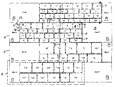
Fig. 1 shows a first embodiment of a set with slabs P1 and P2
having the exemplary dimensions 38 cm x 19 cm and 38 cm x 57 cm and
numbered paving stones 1 - 12 and 21 - 33.
The paving stones 1 - 12 and 21 - 33, respectively, are thereby
CA 02612414 2007-12-17
- 6 -
adjacent to the slabs P1 and P2.
On the whole, a total set
according to Fig. 1 is obtained which can be picked up and placed
by machine.
Consequently, the set comprises all of the paving
stones and slabs shown in Fig. 1. Furthermore, smaller rectangular
sets, e.g. the smaller set B with slab P1 and the paving stones 24,
25, 23b, 26a, 25, 27a, 29, 30a, 26b, 28, 29 and again 28 can be
produced within the frame.
The slabs P and paving stones have (partially designated)
projections A (also see Fig. 3), which form support elements for
the adjacent projections A of adjacent paving stones or slabs.
In particular, the projections of the slabs P are thereby thinner
than the projections of the paving stones, thus, for example, the
thickness T20 of projection A20 is, in particular, less than half
of the thickness T30 of projection 30. This means that joints with
projections A20 (i.e. between adjacent slabs P) are narrower than
joints with projections A30 (i.e. between adjacent paving stones).
As a result, it can be prevented that water to be carried off
reaches between slabs P, since it previously seeps into the wide
joints between paving stones (see Fig. 3). The set according to
the invention thus enables the directed control of the water
drainage behaviour due to concentration on the surface region with
paving stones.
Fig. 1 shows a complete set in which the paving stones 1 - 12 that
are arranged in four rows between the slabs P1 and P2 are
dimensionally adapted precisely to the slabs P1 and P2 and, in the
present case, have an identical overall width of 38 cm (from the
outer side of a projection of paving stone 3 to the outer side of
a projection of paving stone 12 along stretch S). In this way, the
cumulated width of the paving stones 3, 11, 6 and 12 with the joint
widths between the paving stones 3 and 11, 11 and 6 and 6 and 12
also produces the exemplary dimension 38 cm, i.e. a length of the
CA 02612414 2007-12-17
- 7 -
slab P1 (also from the outer side of the projection to the outer
side of the opposite projection).
On the one hand, this results in joints Fl between adjacent paving
stones which pass into joints F2 between adjacent slabs P1 and P2.
Furthermore, there are joints F3 which are arranged between
adjacent rows of paving stones and end at end points E on adjacent
slabs. T-shaped water-drainage joints W are formed which enable a
water drainage from the joint F2 in joints F4 and F5 arranged at a
right angle thereto and in this way do not let water discharged in
joint F3 overflow to the surface e.g. of slab Pl.
The rows of paving stones with the paving stones 21, 22, 22, 21,
and 23a as well as 33, 27b, 30b, 32, 33 and 31 are also
dimensionally adapted to the adjacent slabs P1 and P2 and also have
the exemplary overall width 38 cm.
Fig. 2 shows a further embodiment of a set. In this case also, the
slabs P1 and P2 with the exemplary dimension 38 cm x 57 cm and 38
cm x 19 cm and between them two paving stone rows 21 - 31 and 24 -
28, respectively, are accommodated.
An especially diversified overall impression is produced by the
adjacent arrangement of alternately different slabs P1 and P2.
Furthermore, adjacent paving stones are especially secured in
position by corresponding and mutually supporting projections.
Fig. 3 shows an enlarged representation from Fig. 2 from the region
X. The paving stone 31 is thereby especially secured in position
by designated/typical spacers A of the slab P2, spacer A of the
slab P1 and the spacer of the surrounding adjacent paving stones
23a, 21, 33 and 27a, whereby there are corresponding projections of
the surrounding paving stones and slabs for each of their own
CA 02612414 2007-12-17
- 8 -
projections A and serve as support elements.
In this way, the paving stone 31 is especially secured and locked
in position and can be kept especially stationary when stresses are
introduced.
Fig. 4 to Fig. 7 show a further embodiment of a set with further
paving stones and slabs P that are dimensionally adapted to one
another. Thus, in Fig. 6, the overall width of the rows arranged
between the slabs P2 staggered in a step-like manner correspond to
paving stones, e.g. with the pavings stones 3, 26b and 11 of the
exemplary width 38 cm of the slab P2 arranged above one another.
A sectional representation Y-Y from Fig. 1 can be seen in Fig. 8.
The paving stone 3 and the slab P2 used by way of example have
identical heights h of, for example, 8 cm or 10 cm in their middle
regions. The paving stones and slabs are, optionally, configured
with less height, i.e. less than e.g. 8 cm or 10 cm, on the edges
R, namely by an inclined camber and/or a chamfer, whereby there is
no border or edge but a flowing rounded transition, in particular,
in the transition from the slighter outer edge height to the
heigher middle range M of the paving stone or slab.
In the illustration a according to Fig. 8, the paving stone 3 has
a chamfer (i.e. a reduction in height to the region M) of 0.7 mm
and the slab P has a chamfer of 1.2 mm. As a result, the paving
stone 3 is configured somewhat higher on its periphery than the
slab P2.
In the embodiment according to b, the paving stone 3 does not have
any chamfer at all, i.e. no peripheral slope at all, and the slab
P1 has a peripheral slope of 1.2 mm. Furthermore, the slab P1 can
also not have any peripheral slope (not shown).
CA 02612414 2007-12-17
- 9 -
In the illustration c, the paver has a peripheral slope of 1.3 mm
and the slab a peripheral slope of 1.2 mm. In the illustration d,
the paver has a peripheral slope of 2.5 mm and the slab a
peripheral slope of 1.2 mm.
Thus, in the embodiments a and b, the peripheral region of the
paving stone 3 is raised in comparison to the peripheral region of
slab P2. In the illustrations c and d, the peripheral region of
the paving stone 3 has a lower height than the peripheral region of
slab P2.
Thus, in the illustrations c and d, resultant water to be carried
off, which is led in direction G through the respectively raised
edge of the slab P2, can be stopped and seep into joint F.
In the illustrations a and b, water conveyed in direction H is also
conveyed to the joint F, whereby an overflow onto the surface of
the paving stone 3 is avoided.
Generally, the invention thus enables resultant water currents to
be purposefully conveyed to specific joints by forming higher and
different edges of adjacent pavers and slabs. As a result, an
overflow resultant water currents onto the surfaces of paving
stones and slabs can be prevented.
In this way, in the embodiment of Fig. 1, a channel-like character
of the paving stones vis-à-vis the slabs can be produced by a
recessed and shortened design of the edges of the paving stones in
comparison to the respectively adjacent edges of the slabs, as a
result of which, according to Fig. 1, water can flow off in
direction of arrow Z and an overflow onto the surfaces of the
adjacent surrounding slabs P can be prevented.
CA 02612414 2007-12-17
- 10 -
Alternatively, in the embodiment according to Fig. 1, the edges of
the slabs P1 and P2 can be recessed, so that a channel-like
character is produced in adjacent slabs P1 and P2 vis-a-vis the
adjacent paver surfaces and the water drainage occurs on the water
slabs P (not shown).
According to a further advantageous embodiment, the edges of
adjacent slabs P1 and P2 or adjacent paving stones, e.g. the paving
stones 1, 2 and 3 of Fig. 1, can have different heights. As a
result, the non-skid quality of the surface is increased and an
increased non-skid safety can be obtained when used by people or
vehicles.
In this connection, the invention can be based on a further object
by designing the dimensions of the paving stones and slabs, in
particular the height of the edges, to obtain a specific directed
water-drainage behaviour or a specific improvement of the
passability and non-skid safety.
CA 02612414 2007-12-17
- 11 -
REFERENCE SYMBOLS
1 - 12 Paving stone
21 - 33 Paving stone .
A Projection
B Set
E End point
F Joint
G Direction
H Direction
h Height
P Slab
R Edge
M Centre
Z Direction
S Stretch
T Thickness