Language selection

Search

Patent 2612464 Summary

Third-party information liability

Some of the information on this Web page has been provided by external sources. The Government of Canada is not responsible for the accuracy, reliability or currency of the information supplied by external sources. Users wishing to rely upon this information should consult directly with the source of the information. Content provided by external sources is not subject to official languages, privacy and accessibility requirements.

Claims and Abstract availability

Any discrepancies in the text and image of the Claims and Abstract are due to differing posting times. Text of the Claims and Abstract are posted:

  • At the time the application is open to public inspection;
  • At the time of issue of the patent (grant).
(12) Patent: (11) CA 2612464
(54) English Title: SYNCHRONIZED ACTUATION SYSTEM FOR SLIDING DOORS
(54) French Title: SYSTEME D'ACTIONNEMENT SYNCHRONISE POUR PORTES COULISSANTES
Status: Granted and Issued
Bibliographic Data
(51) International Patent Classification (IPC):
  • E05D 15/12 (2006.01)
  • E06B 3/46 (2006.01)
(72) Inventors :
  • TARREGA LLORET, MIGUEL ANGEL (Spain)
(73) Owners :
  • KLEIN IBERICA, S.A.
(71) Applicants :
  • KLEIN IBERICA, S.A. (Spain)
(74) Agent: MARKS & CLERK
(74) Associate agent:
(45) Issued: 2015-02-17
(22) Filed Date: 2007-11-27
(41) Open to Public Inspection: 2008-05-28
Examination requested: 2012-11-27
Availability of licence: N/A
Dedicated to the Public: N/A
(25) Language of filing: English

Patent Cooperation Treaty (PCT): No

(30) Application Priority Data:
Application No. Country/Territory Date
200603038 (Spain) 2006-11-28

Abstracts

English Abstract

The invention relates to a synchronized actuation system for sliding doors, of the type of those formed, in which the improvements consist of the fact that the pulling grip (1) and the free grip (2) have flanges (12) and in that the belt (4) and free (2) and pulling (1) grips are joined by means of a connecting shoe (3). With this configuration it is possible to carry out assembly and maintenance operations vertically and therefore in situ, this being a substantial improvement of the main patent.


French Abstract

Linvention concerne un système dactionnement synchronisé pour portes coulissantes, du type de ceux formés, dans lesquels les améliorations résident dans le fait que la poignée de tirage (1) et la poignée libre (2) possèdent des brides (12) et dans le fait que la courroie (4) et les poignées libre (2) et de tirage (1) sont jointes au moyen dun sabot de liaison (3). Avec cette configuration, il est possible deffecteur des opérations dassemblage et dentretien verticalement et, par conséquent, in situ, ceci représentant une amélioration importante du brevet principal.

Claims

Note: Claims are shown in the official language in which they were submitted.

4
CLAIMS
1. A
synchronized actuation system for sliding doors, comprising a free grip and
a pulling grip holding the panels of a door, wherein a transmission belt
enables the
movement of the grips on a guide, comprising furthermore a connecting shoe, a
first pair of
screws and a second pair of screws, and wherein the belt and pulling grip are
joined by
means of the connecting shoe, wherein the pulling grip and the free grip have
a horizontal rib
on one of their flanges; and wherein a first pair of holes suitable for the
passage of the first
pair of vertically oriented screws for the joining between the shoe and the
transmission belt
have been made in the horizontal rib of the pulling grip, and in that the
second pair of
vertically oriented screws, for the joining between the shoe and pulling grip,
screwed in the
horizontal rib of the pulling grip cooperates with a second pair of holes; and
wherein the
connecting shoe is formed by a horizontal base in which the second pair of
holes, for the
joining with the pulling grip, is made and from which the first pair of
vertically oriented screws
for the joining with the belt emerges, and wherein a wall extends vertically
from said
horizontal base, from which wall there emerges in turn an upper cover, leaving
a gap
through which the belt passes and is trapped by the first pair of vertically
oriented screws
between this cover and a horizontal intermediate base, the first pair of
vertically oriented
screws being screwed in the horizontal intermediate base.

Description

Note: Descriptions are shown in the official language in which they were submitted.


CA 02612464 2007-11-27
1
SYNCHRONIZED ACTUATION SYSTEM FOR SLIDING DOORS
Obiect of the Invention
The object of this specification is to perfect and improve synchronized
actuation
__ systems for sliding doors, consisting of the use of a connecting shoe in
the synchronic
actuation mechanism.
The invention is especially suitable to be applied to sliding doors, which can
move with respect to fixed panels framing the practicable passage area
assisted by
said doors.
__ Background of the Invention
The applicant is the proprietor of invention patent ES 2246673, the object of
which is to present a device for the synchronized actuation of sliding doors
with two
connecting grips and their corresponding connection parts. The applicant is
also the
proprietor of invention patent P200502261, a mechanism for a sliding glass
leaf, in
__ which the suspension grip of the sliding door is improved.
Nevertheless, in both systems, the access to the internal components of the
mechanism (suspension device) is carried out through a lid consisting of a
gallery
profile, and always horizontally. This arrangement of the elements makes it
necessary
to always leave a clearance allowing the installation of the system and future
__ maintenance such as, for example, adjustments, substitution of parts, etc.
Description of the Invention
The improved synchronized actuation system for sliding doors, object of this
invention patent, is designed to palliate, or where appropriate, eliminate the
technical
drawbacks considered.
The introduced improvement consists of the use of a connecting shoe joined to
the pulling grip or suspension device by means of screws. The suspension
devices
have also been modified with respect to that claimed in the main patent so as
to
provide it with a flange and holes suitable joining it to the connecting shoe.
The operation of the invention is as follows. The grips holding the door, both
the
__ pulling grip and the free grip (both are suspension devices), are first
centered. Once
the grips are in place, the connecting shoe is fixed to the pulling grip. To
that end, the
connecting shoe is moved along the transmission belt, until the holes of the
shoe are
opposite to the holes of the pulling grip, both elements being fixed by
screws. Finally,
the suspension device ¨ connecting shoe assembly is fixed to the transmission
belt by
__ means of screws, each of them being fixed between two teeth of the
mentioned belt.

CA 02612464 2014-06-17
2
In accordance with an aspect of the present invention, there is provided a
synchronized actuation system for sliding doors, of the type formed by a free
grip and a
pulling grip joined to the panels of the doors, wherein the transmission belt
enables the
movement of the grips and on a guide wherein the pulling grip and the free
grip have
flanges; and wherein the belt and pulling grip are joined by means of a
connecting shoe
that is not integrated in the structure of the actual pulling grip.
In accordance with another aspect of the present invention, there is provided
a
synchronized actuation system for sliding doors, comprising a free grip and a
pulling
grip holding the panels of a door, wherein a transmission belt enables the
movement of
the grips on a guide, comprising furthermore a connecting shoe, a first pair
of screws
and a second pair of screws, and wherein the belt and pulling grip are joined
by means
of the connecting shoe, wherein the pulling grip and the free grip have a
horizontal rib
on one of their flanges; and wherein a first pair of holes suitable for the
passage of the
first pair of vertically oriented screws for the joining between the shoe and
the
transmission belt have been made in the horizontal rib of the pulling grip,
and in that
the second pair of vertically oriented screws, for the joining between the
shoe and
pulling grip, screwed in the horizontal rib of the pulling grip cooperates
with a second
pair of holes; and wherein the connecting shoe is formed by a horizontal base
in which
the second pair of holes, for the joining with the pulling grip, is made and
from which
the first pair of vertically oriented screws for the joining with the belt
emerges, and
wherein a wall extends vertically from said horizontal base, from which wall
there
emerges in turn an upper cover, leaving a gap through which the belt passes
and is
trapped by the first pair of vertically oriented screws between this cover and
a
horizontal intermediate base, the first pair of vertically oriented screws
being screwed
in the horizontal intermediate base.
The following advantages are obtained with respect to the arrangement used in
the current state of the art by means of using the connecting shoe:
- Access to the suspension device can be carried out vertically, the
horizontal
clearance disappears, the system becoming more compact and multipurpose
because it allows installation in any place.
- Any handling, either due to repair or due to assembly, is simplified with
respect
to that claimed in the main patent.
Brief Description of the Drawings
A series of drawings is very briefly described below, which aid in better
understanding the invention and are expressly related to an embodiment of said

CA 02612464 2014-06-17
2a
invention, presented as a non-limiting example thereof.
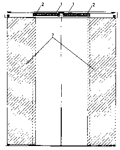
- Figure 1 is a view of the free and pulling grips integrating the
actuation system
object of this invention patent.
- Figure 2 is a view of the connecting shoe.
- Figure 3 is a view of the connecting shoe joined to the pulling grip and
to the
transmission belt.
- Figure 4 is a view of the actuation system assembled in respective
sliding
doors.
Preferred Embodiment of the Invention
As can be observed in the attached figures, both the pulling grip (1) and the
free
grip (2) have been modified, with respect to the main patent, with flanges
(12). Holes
(11) suitable for the passage of the screws (32) for the joining between the
shoe (3)
and the transmission belt (4) have been made in the pulling grip (1) in the
flange (12).
In the same manner, there are two screws (5) for the joining between the shoe
(3) and
pulling grip (1) in the pulling grip (1).
The formation of the connecting shoe (3) can be observed in Figure 2.
Describing it from its lower part to its upper part, the connecting shoe (3)
is formed by a
base (35) in which the holes (31) for the joining with the pulling grip (1)
are made and
from which respective screws (32) for the joining with the belt (4) emerge. A
wall (33)
extends vertically from the base, from which wall there emerges in turn an
upper cover
(34), leaving a gap through which the belt (4) will pass and be trapped by the
screws
(32) between this cover (34) and an intermediate base (35).
Figure 3 shows how the connecting shoe (3) is joined to the transmission belt
(4) in the pulling grip (1) and how the latter rests on the guide (6) thanks
to the wheel of
the pulling grip (1).

CA 02612464 2007-11-27
3
Figure 4 shows the assembly of the system object of the invention in the
panels
(7) of the doors.
Having sufficiently described the nature of this invention patent, it must
only be
added that the invention can undergo certain variations in shape and materials
such
that said alterations do not substantially modify the features claimed below.

Representative Drawing
A single figure which represents the drawing illustrating the invention.
Administrative Status

2024-08-01:As part of the Next Generation Patents (NGP) transition, the Canadian Patents Database (CPD) now contains a more detailed Event History, which replicates the Event Log of our new back-office solution.

Please note that "Inactive:" events refers to events no longer in use in our new back-office solution.

For a clearer understanding of the status of the application/patent presented on this page, the site Disclaimer , as well as the definitions for Patent , Event History , Maintenance Fee  and Payment History  should be consulted.

Event History

Description Date
Letter Sent 2023-11-27
Common Representative Appointed 2019-10-30
Inactive: Cover page published 2015-06-19
Inactive: Acknowledgment of s.8 Act correction 2015-05-12
Correction Request for a Granted Patent 2015-03-10
Grant by Issuance 2015-02-17
Inactive: Cover page published 2015-02-16
Pre-grant 2014-12-02
Inactive: Final fee received 2014-12-02
Notice of Allowance is Issued 2014-07-21
Letter Sent 2014-07-21
Notice of Allowance is Issued 2014-07-21
Inactive: Approved for allowance (AFA) 2014-07-14
Inactive: QS passed 2014-07-14
Amendment Received - Voluntary Amendment 2014-06-17
Inactive: S.30(2) Rules - Examiner requisition 2013-12-17
Inactive: Report - QC passed 2013-12-12
Letter Sent 2012-12-06
Request for Examination Received 2012-11-27
Request for Examination Requirements Determined Compliant 2012-11-27
All Requirements for Examination Determined Compliant 2012-11-27
Application Published (Open to Public Inspection) 2008-05-28
Inactive: Cover page published 2008-05-27
Inactive: First IPC assigned 2008-05-07
Inactive: IPC assigned 2008-05-07
Inactive: IPC assigned 2008-04-30
Inactive: Applicant deleted 2008-01-23
Inactive: Filing certificate - No RFE (English) 2008-01-14
Filing Requirements Determined Compliant 2008-01-14
Application Received - Regular National 2008-01-14

Abandonment History

There is no abandonment history.

Maintenance Fee

The last payment was received on 2014-11-19

Note : If the full payment has not been received on or before the date indicated, a further fee may be required which may be one of the following

  • the reinstatement fee;
  • the late payment fee; or
  • additional fee to reverse deemed expiry.

Please refer to the CIPO Patent Fees web page to see all current fee amounts.

Owners on Record

Note: Records showing the ownership history in alphabetical order.

Current Owners on Record
KLEIN IBERICA, S.A.
Past Owners on Record
MIGUEL ANGEL TARREGA LLORET
Past Owners that do not appear in the "Owners on Record" listing will appear in other documentation within the application.
Documents

To view selected files, please enter reCAPTCHA code :


To view images, click a link in the Document Description column. To download the documents, select one or more checkboxes in the first column and then click the "Download Selected in PDF format (Zip Archive)" or the "Download Selected as Single PDF" button.

List of published and non-published patent-specific documents on the CPD .

If you have any difficulty accessing content, you can call the Client Service Centre at 1-866-997-1936 or send them an e-mail at CIPO Client Service Centre.


Document
Description 
Date
(yyyy-mm-dd) 
Number of pages   Size of Image (KB) 
Abstract 2007-11-27 1 12
Description 2007-11-27 3 112
Claims 2007-11-27 1 32
Drawings 2007-11-27 3 83
Representative drawing 2008-05-05 1 19
Cover Page 2008-05-16 1 46
Claims 2014-06-17 1 31
Description 2014-06-17 4 157
Cover Page 2015-01-28 1 48
Cover Page 2015-05-12 2 77
Filing Certificate (English) 2008-01-14 1 159
Reminder of maintenance fee due 2009-07-28 1 110
Reminder - Request for Examination 2012-07-30 1 117
Acknowledgement of Request for Examination 2012-12-06 1 189
Commissioner's Notice - Application Found Allowable 2014-07-21 1 162
Commissioner's Notice - Maintenance Fee for a Patent Not Paid 2024-01-08 1 541
Fees 2012-11-27 1 155
Fees 2009-11-10 1 65
Fees 2010-11-17 1 65
Fees 2011-11-01 1 63
Correspondence 2014-12-02 1 51
Correspondence 2015-03-10 3 90
Maintenance fee payment 2021-10-15 1 26
Maintenance fee payment 2022-09-15 1 26