Note: Descriptions are shown in the official language in which they were submitted.
CA 02613099 2007-12-21
WO 2006/133513 PCT/AU2006/000846
1
VEHICLE ACCESS SYSTEM.
FIELD OF THE INVENTION
This invention relates to access systems for vehicles, specifically the
access system for large earth moving equipment.
BACKGROUND OF THE INVENTION
Access systems for large earth moving equipment often incorporate a set
of deployable stairs so that the operator can climb up into the cab without
climbing a vertical ladder that may have a negative inclination if the
equipment is
not parked on level ground.
Once the operator is on the machine the operator retracts the stairs so that
they are not hanging down and the ground clearance of the machine is increased
thus minimizing the probability of the stairs being damaged by contacting
rocks
when the machine is in motion.
The stairs need to be retracted so that other personal cannot climb up onto
the machine with out the operator's knowledge. Should a person be on the
stairs
without the operator's knowledge then the possibilities for injury to that
person are
numerous. The possible injuries could range from overbalancing the person to
crushing trapping the person between the moving parts of the equipment and the
adjoining bodywork of the equipment.
The systems used for retracting the stairs can vary but generally they rely
on either an electric or hydraulic system that is manually actuated by the
operator.
Should an emergency occur such as a fire it is necessary for the operator
to activate a switch to lower the stairs to evacuate the machine or find an
alternative way off the machine or equipment. This can be a particular problem
if
there is a fire in the vicinity of the stair operating switch.
Should the operator forget to retract the stairs and drive the machine off, it
is possible to destroy the stairs, causing an expensive repair, downtime and
generating safety issues, resulting from damage to an emergency exit.
Another known problem of prior art ladder retraction systems is that, when
retracted, the ladder is either held retracted by hydraulic/pneumatic
pressure,
such as provided by the lifting cylinder, or once retracted a locking pin is
used to
CA 02613099 2007-12-21
WO 2006/133513 PCT/AU2006/000846
2
lock the ladder in place. The locking pin itself can be driven by a small
hydraulic/pneumatic cylinder.
Problems with such systems are typically associated with bounce. The
ladder can bounce during movement of the vehicle, causing failure of the
lifting
system. Also, damage caused to the locking pin by ladder bounce can result in
failure of the locking pin mechanism.
Where the vehicle has an interlock system, such as a proximity switch,
connected to the ladder retraction mechanism or to the locking pin actuating
mechanism to prevent movement or starting the vehicle until the interlock is
operated, ladder bounce can result in the switch operating thereby stopping or
shutting down the vehicle unexpectedly. This results in excess downtime of the
vehicie and loss of productivity.
With the aforementioned in mind, it is an object of the present invention to
provide a system for retracting a ladder that allows a user to physically halt
initial
retraction but provides sufficient force to maintain the ladder retracted when
retracted.
SUMMARY OF THE INVENTION
With this in view, there is provided A vehicle access system including an
access means and a retracting mechanism for the access means, wherein a force
applied to the access means is sufficient to retract the access means from a
fully
deployed position to a partially retracted position but not sufficient to not
be
physically resisted by a user during at least part of the retraction.
Thus, advantageously, an access system for a vehicle is provided that will
allow a user to overcome the retraction forces during at least part of the
retraction
process to thus prevent further retraction, and optionally commence re-
deployment of the stairs to alleviate risk of injury to the user. It will be
appreciated that a user wishing to prevent retraction of the stairs will be
able to
safely apply sufficient force or weight to overcome retraction forces and thus
halt
or reverse the retraction process.
It will be appreciated that the term access means may encompass stairs,
steps and ladders for accessing vehicles.
A further aspect of the present invention provides a retractable access
system for a vehicle including an access means and a retracting mechanism for
CA 02613099 2007-12-21
WO 2006/133513 PCT/AU2006/000846
3
said access means, wherein an applied moving force is translated into a
variable
force for retracting the access means wherein torque generated to retract the
access means exceeds torque required to retract the access means by an
amount that is able to be resisted by a user for a portion of the retraction
phase
and increases to a greater force for a latter portion of the retraction phase.
Preferably, when the access means is fully retracted, a force may be exerted
on
the retracted access means sufficient to hold the access means in a retracted
position without the need for auxiliary restraining means.
Preferably torque provided to retract the access means may vary through
at least part of the retraction cycle.
The torque generated may vary throughout the retraction cycle so that the
torque provided to retract the access means from 0-70% of the retraction cycle
just exceeds the required torque necessary to retract the access means, and
between 70-100% of the retraction cycle the torque generated may increase such
that when the access means is fully retracted the torque applied to the access
means is sufficient to hold the access means in the retracted position without
the
need for auxiliary restraining means.
This provides the advantage that when the access means are within reach
or use of ground personnel, the forces retracting the access means may be
countered by the user. When the access means are out of the reach of ground
personnel, the force applied through the retraction mechanism increases so
that
the access means are firmly held in the retracted position.
Preferably the retracting/deploying system may be connected into a
hydraulic pilot control circuit and/ora hand brake hydraulic circuit of the
vehicle.
This has the advantage that when the hand brake is released the access means
are automatically retracted. When the park brake is applied or if there is a
hydraulic failure the access means are deployed.
The geometry of the parts of the linkage is configured to provide a required
torque profile.
A further aspect of the present invention provides a method of retracting an
access means including the steps of;
CA 02613099 2007-12-21
WO 2006/133513 PCT/AU2006/000846
4
a) applying a first lifting force during an initial portion of a retraction
phase
of a deployed access means, the applied first lifting force being equal to or
greater than a minimum force required lift the access means,
and b) subsequently applying a second lifting force during a secondary
portion of the retraction phase of the deployed access means, the second
lifting
force being greater than the minimum required to lift the ladder.
Preferably the first lifting force may be less than a manual effort required
to
retard retraction of the access means. Preferably the manual effort may be
sufficient to reverse retraction of the access means and commence re-
deployment thereof.
Preferably the second lifting force (torque) may diverge (and increase)
compared to the required lifting force during the secondary portion of the
retraction phase.
Preferably the initial portion of the retraction phase may be about two
thirds of the entire retraction phase from commencement to fully retracted.
BRIEF DESCRIPTION OF THE DRAWINGS
Figure 1 is a side view of an embodiment of the present invention showing
the mechanical arrangement of the retracting mechanism.
Figure 2 is a graph showing the torque required and the torque applied to
retract the stair from +45 to -90 according to an embodiment of the present
invention.
Figure 3 is a graph showing the torque required and the torque applied to
retract the stair from +60 to -120 according to an embodiment of the present
invention.
Figure 4 shows a graph of excess lift torque for a ladder retracting through
90 in accordance with an embodiment of the present invention.
Figure 5 shows a graph of excess lift torque for a ladder retracting from 45
extended to -90 retracted, according to an embodiment of the present
invention.
Figures 6a to 6d show a series of images of a set of vehicle stairs being
retracted from a deployed position to a fully retracted position according to
an
embodiment of the present invention.
CA 02613099 2007-12-21
WO 2006/133513 PCT/AU2006/000846
DETAILED DESCRIPTION.
It will be convenient to describe the present invention with reference to the
accompanying Figures and examples that illustrate possible arrangements of the
present invention.
5 In the preferred embodiment the stairs 10 operate with rotation around a
fixed point at the inboard end of the stairs 10 it would be clear to a person
skilled
in the art that other possible arrangements are possible.
The access system consists of a set of access stairs 10 actuated by a
retraction mechanism 25.
The stairs 10 are relatively conventional for large earthmoving equipment
and may have a normal operating angle of between 45 and 70 relative to the
horizontal direction and retract through an arc of between 90 and 180 . The
stairs 10 may also include a hand rail 27 and textured treads (not shown) to
provide a secure access way to the equipment.
The retraction mechanism 25 has been chosen to as to provide a unique
non linear torque response to the stairs 10 from a fixed force linier output.
In the
present example the linier force is provided by a hydraulic ram 40. The
retraction
mechanism 25 is optimized to provide a varying torque to lift the stairs 10
depending on where in there arc of retraction the stairs 10 are. When the
stairs
10 are iri the fully deployed position such that an operator could use the
stairs 10
to access the equipment the torque force applied to retract the stairs 10 is
enough
to raise the stairs 10, however the torque applied only exceeds the torque
required by a relatively small amount so that a person would be able to stop
the
stairs 10 from retracting. This has the advantage that should a person be on
the
stairs 10 or holding the stairs 10 when they are retracted by the equipment
operator the stairs 10 will not retract and injure the person holding the
stairs 10.
Once the stairs 10 are retracted above the reach of any ground personal or
equipment that may get caught up with the stairs 10 the torque applied to the
stairs 10 is increased relative to the torque required. The point of
increasing
torque is set by the geometry of the retraction mechanism 25. The point of
increasing torque is determined during design of the retraction mechanism 25
and
may vary according to the intended application. For example a small earth
moving machine or equipment may have the stair travel through 70 before the
CA 02613099 2007-12-21
WO 2006/133513 PCT/AU2006/000846
6
stairs 10 are out of reach of ground personal and therefore may be designed to
have the torque increase at about this point. If the stairs 10 are being
fitted to a
larger machine the stairs 10 may only need to be retracted through 450 or even
less before they are out of reach of ground personal.
The increase of torque applied to the stairs 10 provides an advantage in
that by the time the stairs 10 are in the fully retracted position there is a
larger
force holding the stairs 10 in the fully retracted position. This increased
force
applied to the stairs 10 eliminates the need for any additional retention
mechanisms to be installed to stop the stairs 10 moving uncontrollably when
the
equipment is in operation.
Another advantage of the retraction mechanism 25 is that should the stairs
10 be restrained, by contact with fixed objects for example rocks or other
vehicles
the retraction mechanism 25 will not be damaged as the torsional force
available
to retract the stairs 10 is initially not significantly greater that the force
required in
retracting the stairs 10.
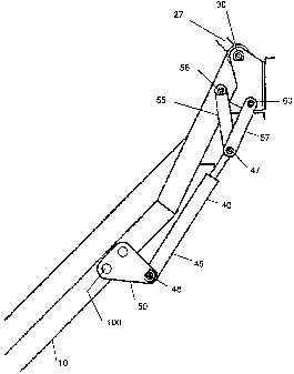
Figure 1 shows a general arrangement of the retraction mechanism 25.
The stairs 10 are pivotally mounted to the equipment at the stair main pivot
30.
The retraction mechanism 25 includes a hydraulic ram 40, having a first end 45
pivotally connected to a hydraulic ram 40 mounting bracket 50 at the hydraulic
ram pivot 46. The hydraulic ram bracket 50 is affixed to the stair 10 at some
distance along the stair 10 remote from the stair main pivot 30 that is
located on
the earth moving equipment (not shown). The hydraulic ram bracket 50 is
designed to move the hydraulic ram pivot some distance from the stair 10 this
distance is called the hydraulic ram offset 100.
The second end 47 of the hydraulic ram 40 is pivotally connected to two
linkages. One of the linkages is called the ram stair linkage 55. The ram
stair
linkage 55 runs from the second end 47 of the hydraulic ram 40 to the
intermediate pivot 56 located on the stairs 10 at a point between the main
pivot
and the hydraulic ram mounting bracket 50.
30 The second linkage connected to the second end 47 of the hydraulic ram
is called the ram body linkage 57. The ram body linkage 57 runs from the
second end 47 of the hydraulic ram 40 to the body pivot point 60 located on
the
earth moving equipment at some point offset from the stair main pivot 30.
CA 02613099 2007-12-21
WO 2006/133513 PCT/AU2006/000846
7
When in operation the hydraulic ram 40 extends and applies a force
between the ram pivot 46 and the equipment through the ram body linkage 57.
As the ram pivot 46 is offset by the use of the hydraulic ram mounting bracket
50
(the hydraulic ram offset 100) and the ram body linkage 47 is mounted on the
earth moving equipment at the body pivot 60 (offset from the main pivot 30)
the
force generated by the extending hydraulic cylinder 40 is converted to a
torque
applied to the stair 10 around the stair main pivot 30.
The force applied by the hydraulic ram 40 may be adjusted so that when
the stairs 10 are in a fully deployed an operator would use the stairs 10 the
forces
applied through the hydraulic ram 40 and translated into torque are sufficient
to
counteract the weight of the stairs 10 so that the stairs 10 can be retracted.
The
torque forces are however not high enough to lift a person, the stairs 10 may
even be stopped from raising by being held by a person. Once the arc of
retraction has progressed so that the stairs 10 are not within reach of ground
personnel the torque applied increases so that once the stairs 10 are fully
retracted the torque applied to the stairs 10 is sufficient to hold the stairs
10 in the
fully retracted position and prevent them moving when the earth moving
equipment is in operation.
Figure 2 shows a typical force profile for a set of stairs 10 operating in the
+450 to - 90 arc. In this graph the dotted line shows the torque required to
raise
the stairs 10 while the solid line represents the torque applied. It can be
seen that
through the arc of +45 to -70 the torque supplied is in excess of the torque
required to raise the stairs 10 by approximately 10-20 kgm. When the stair 10
are
in the fully retracted position the force required to overcome the tortional
force
provided through the retraction mechanism 25 is approximately 80 kgm. These
values may be changed by adjusting the force output of the hydraulic ram 40.
Figure 3 shows a typical force profile for a set of stair operating in the +60
to -120 arc. In this graph the dotted line shows the torque required to raise
the
access stairs 10 while the solid line represents the force applied to the
stairs 10.
It can be seen that through the arc of +60 to -60 the torque supplied in
excess
of the torque required is approximately 5 kgm. When the stairs 10 is in the
fully
retracted position the force required to overcome the hydraulic force is
substantially more.
CA 02613099 2007-12-21
WO 2006/133513 PCT/AU2006/000846
8
In general the retraction mechanism 25 is set up so that with a constant
output from a hydraulic ram 40 the torsion forces applied to the stairs 10
exceed
the forces required to lift the stairs 10 for approximately 2/3 of the arc. In
the last
third of the arc approaching the fully retracted position the induced torque
force
increases so that the stairs 10 is firmly held in the retracted position and
doesn't
move excessively while the equipment is in operation.
Examples of the retraction mechanism 25 are given in Table 1...
Table 1
Description Dimension Dimension
45 C to 90 C 60 C -120 C
Stair main pivot 30 to extreme end (not 2000 mm 700 mm
shown)
Hydraulic Ram Offset 100 100 mm 200 mm
Hydraulic Ram mounting bracket 50 to 1030 mm 550 mm
stair main pivot 30
Ram stair linkage 55 (pivot centre to 255 mm 150 mm
pivot centre)
Ram body linkage 57 (pivot centre to 220 mm 150 mm
pivot centre)
Distance from stair pivot 56 to main 160 mm 50 mm
pivot 30
Stair main pivot to body pivot 60 200 mm 65 mm
The control for the hydraulic ram 40 of the retraction mechanism 25 may
be operated through the pilot circuit for the park brakes on rubber tyred
equipment or the pilot circuit for the controls on tracked equipment. In large
earth
moving equipment the park brakes are normally on and hydraulic pressure is
used to release the brakes. Alternately the hydraulic pressure for the
retraction
mechanism 25 may be provided by the main hydraulic system or from a separate
hydraulic pump.
The graph in Figure 4 depicts excess lift torque for a vehicle ladder or
stairs retracting through 90 e.g. from near vertical when deployed to near
horizontal when fully retracted. The graph plots Lift torque (kgm) over and
above
the torque required to commence lifting the ladder against the degrees of
CA 02613099 2007-12-21
WO 2006/133513 PCT/AU2006/000846
9
extension of the ladder. That is, for example, a graph of the difference
between
the dotted line and the solid line shown in each of figures 2 and 3.
In the embodiment shown, excess lift torque is minimal for initial lift
(retraction) (right hand portion of curve) and thereafter increases once the
ladder
has retracted sufficiently that a user or personnel is either not in danger of
injury,
or the ladder is considered sufficiently retracted that the user has had
sufficient
warning of retraction or the ladder is out of reach.
It may be appreciated that although ideally the excess lift torque would be
linear or near linear i.e. a straight line prior to the increase portion of
the graph,
physical, mechanical and force characteristics of the system approximate or
approach the ideal, which is sufficient to provide an effective and efficient
working
system without requiring over-engineering or more complex configurations.
Figure 5 shows an alternative excess lift torque curve being for a ladder
retracting from 45 angle of extension (from the horizontal) to -90 retracted
(vertical). Again, ideally the right hand portion of the graph (before the
steep
sloped section) would be linear.
It will be appreciated that the nearer the generated torque (solid line in
Figures 2 and 3) is to the required lift torque in the right hand dise of each
graph
across the range of angles, the less manual force is required to halt
retraction of
the ladder. Also, in the left hand (steep) section of the graph, the more the
solid
(applied force) line deviates away from and above the dotted line, the greater
the
force (torque) applied, and the greater the holding force can be when the
ladder is
fully retracted. Thus, for the first approximately two thirds of the
retraction
process, the difference between required and applied torque can be minimal,
though applied should not be less than the required torque, the easier a
person
can manually stopped retraction (lift) of the ladder. However, once the ladder
has
approximately one third retraction travel to go, lift force (torque) can be
significantly increased, thus speeding up retraction and also providing
sufficient
force to maintain the laddr retracted without needing additional restraining
means
such as a locking pin mechanism (though such can be provided if required).
Figures 6a to 6d show a series of steps in the retraction process. Figure
6a shows the steps 101 fully extended (approx 45 from horizontal). The upper
end 102 would normally be mounted to a vehicle (not shown). The steps are
CA 02613099 2007-12-21
WO 2006/133513 PCT/AU2006/000846
pivoted to a retracted position, with deployment being the reverse of
retraction,
though if required, the force curve for deployment may differ from the force
curve
for retraction. Figure 6b shows the steps approximately one third through the
retraction process. The lower end 103 is almost horizontal with the upper end
5 102. It will be appreciated that the steps or ladders etc. may take various
forms
and arrangements e.g. pivoted in the middle so as to also collapse to a
shorter
retracted form. Also the steps or ladders may retract sideways e.g. pivot
sideways. However, the force curve nature of retraction according to the
present
invention remains the same.
10 Lifting force is provided via an actuating cylinder 104 applying force
between a linkage at the upper end of the steps and a connection 105
approximately halfway down the steps. It will be appreciated that the
arrangement of actuators and linkages may vary depending on the form and
application of the steps, though the present invention remains unchanged.
Figure 6c shows the steps at approximately two thirds retracted.
Consequently, the steps are, in this embodiment, considered sufficiently
retracted
as to be generally out of reach of personnel on the ground or that personnel
on
the vehicle/steps have had sufficient time (warning) of retraction of the
steps and
therefore are deemed either clear of the steps or have had sufficient time to
apply
force during the initial retraction phase to halt retraction or to manually
cause the
steps to re-deploy by overcoming the applied lift torque.
Figure 6d shows the steps fully (vertically) retracted. Between phases 6c
and 6d, torque applied to the steps increases, thereby diverging the applied
lift
torque curve away from the required lift torque curve. Force applied at the
fully
retracted position is sufficient to prevent or mitigate ladder/step bounce,
thereby
reducing risk of damage, injury or vehicle failure (eg due to bounce causing a
proximity switch to inadvertently operate).
While the method and apparatus has been explained by illustrative
examples it will be appreciated by those skilled in the art that varying
embodiments and applications are within the teaching and scope of the present
invention. The examples presented here in are by way of example and should
not be construed as limiting the scope of the present invention.