Note: Descriptions are shown in the official language in which they were submitted.
CA 02613231 2007-12-21
WO 2006/136860 PCT/GB2006/002349
1
1 Improved Energy Storage System
2
3 The present invention relates to the field of energy
4 efficiency, and in particular a system and method for
improving the use of energy.
6
7 In February 2003, the UK Government issued an Energy
8 White Paper in which the need for increased energy
9 efficiency was outlined. In short, targets to reduce
carbon emissions by significant amounts can only be met
11 if at least 50% of the reductions are achieved through
12 energy efficiency. This is therefore at the heart of UK
13 energy policy. Reducing the demand on electricity supply
14 networks will lead directly to a reduction in carbon
emissions.
16
17 Another problem is the issue of fuel poverty, millions of
18 households in the UK cannot afford to heat their homes
19 sufficiently. Some heating systems are inefficient and
expensive to run, and a cheaper, more energy efficient
21 alternative is very desirable.
22
23 Energy from the sun is one of the most widely available
24 energy sources, and one of the most obvious. Solar
panels are used, primarily for generating electricity but
CA 02613231 2007-12-21
WO 2006/136860 PCT/GB2006/002349
2
1 also solar water heating panels are known. Solar water
2 heating panels are used to provide hot water supplies.
3
4 The disadvantage of such solar water heating panels is
that they do not always produce enough heat to provide,
6 for example, a domestic hot water supply. There are
7 periods, during the night and in cloudy conditions, when
8 little or no energy will be produced and standard
9 domestic water heating must be relied upon. Therefore it
increases energy efficiency in a household only under
11 appropriate conditions.
12
13 In light of recent heightened awareness of the need for
14 more efficient use of energy, the benefits of using heat
pumps are clear. A heat pump is a heat exchanger which
16 transfers heat from one location to another location,
17 effectively swapping hot for cold, or vice versa. A
18 refrigerator is a heat pump, where the heat is taken out
19 of the food storage area and dispersed through a sink on
the rear of the appliance.
21
22 An alternative type of heat pump is used to harness the
23 benefits of various kinds of renewable energy, in
24 particular heat from ambient air, or underground warmth,
or even from sunlight-heated water or ground. In this
26 type of system, energy efficiency is increased
27 significantly. A small amount of electricity is required
28 to move heat energy from one location to another, but the
29 energy transferred by the heat is generally several times
the energy that would be generated by the electricity
31 alone. This offers a way of boosting, for example,
32 conventional water heating systems for homes and
33 businesses. Given that 30% of C02 emissions were
CA 02613231 2007-12-21
WO 2006/136860 PCT/GB2006/002349
3
1 attributed to heating buildings in 1997, it is clear that
2 total emissions can be drastically reduced by employing
3 more energy efficient practices.
4
However, conditions are not always such that heat pumps
6 can be employed at optimal efficiency, given that the
7 source of heat from which the energy is drawn may not
8 always be at the optimum temperature for operation.
9 Furthermore, weather conditions and the time of year also
contribute to some extent to the efficiency of heat
11 pumps.
12
13 It is therefore an object of the present invention to
14 provide a system for more efficient use of energy.
16 Summary of Invention
17
18 According to a first aspect of the present invention,
19 there is provided a system, the system comprising;
an energy extraction means, the energy extraction
21 means adapted to extract energy from a source;
22 an energy storage means, the energy storage means
23 adapted to retrievably store the extracted energy;
24 an energy output means, the energy output means
adapted to controllably release energy from the system;
26 an energy transferring means, the energy
27 transferring means adapted to transfer energy between the
28 energy extraction means, the energy storage means, and
29 the energy output means; and
an energy transfer controlling means, the energy
31 transfer controlling means adapted to control the
32 transfer of energy between the energy extraction meaizs,
33 the energy storage means, and the energy output means.
CA 02613231 2007-12-21
WO 2006/136860 PCT/GB2006/002349
4
1
2 Preferably the energy transfer controlling means operates
3 so as to optimise the energy flow into the output means.
4
Preferably the energy storage system further comprises a
6 heat pump, the heat pump located between the energy
7 storage means and the energy output means.
8
9 Preferably the energy transferring means comprises at
least one conduit connecting two or more of the
11 components of the system.
12
13 Preferably the conduit is hollow and contains a fluid,
14 the fluid adapted to store and to transfer heat energy by
flowing therein.
16
17 Optionally the fluid is glycol.
18
19 Alternatively the fluid is water.
21 Preferably the energy extraction means comprises a solar
22 heating panel, the solar heating panel adapted to receive
23 energy from the sun and impart thermal energy to a fluid
24 in the solar heating panel.
26 Preferably the energy extraction means further comprises
27 a temperature sensor.
28
29 Alternatively the energy extraction means comprises one
or more hoses filled with a fluid, the hose adapted to
31 trap thermal energy from the surroundings.
32
CA 02613231 2007-12-21
WO 2006/136860 PCT/GB2006/002349
1 Alternatively'the energy extraction means comprises a
2 hose located within a tank containing a volume of fluid,
3 the hose adapted to extract thermal energy from the
4 volume of fluid.
5
6 Preferably the energy extraction means further comprises
7 one or more heating elements located on or in the tank
8 and adapted to provide thermal energy to the fluid.
9
Preferably the energy extraction means comprises a wind
11 turbine adapted to provide electrical energy to the one
12 or more heating elements.
13 Preferably the energy storage means comprises one or more
14 ground loops.
16 Preferably the one or more ground loops are inserted in
17 respective boreholes.
18
19 Alternatively the energy storage means comprises a tank
containing a volume of fluid.
21
22 Preferably the energy transfer controlling means
23 comprises at least one valve, the at least one valve
24 located within the system so as to control the flow of
the fluid within the system.
26
27 Preferably the energy transfer controlling means further
28 comprises a controller means, the controller means
29 adapted to control the at least one valve in response to
a temperature signal received from the temperature
31 sensor.
32
CA 02613231 2007-12-21
WO 2006/136860 PCT/GB2006/002349
6
1 Preferably the energy output means comprises a cylinder,
2 the cylinder adapted to receive and retain a quantity of
3 fluid.
4
Preferably the cylinder comprises an output means, the
6 output means adapted to selectively flow fluid into the
7 system or into an external system.
8
9 Optionally the external system comprises a hot water
system.
11
12 Alternatively the external system comprises a heating
13 system.
14
According to a second aspect of the present invention,
16 there is provided a cylinder adapted for use in the
17 system of the first aspect, the cylinder comprising a
18 first reservoir and a second reservoir, wherein the
19 cylinder further comprises a means of diverting fluid
from at least one of the energy extraction means and the
21 energy storage means to either reservoir.
22
23 Preferably the cylinder is vented.
24
Alternatively the cylinder is unvented.
26
27 Preferably the first reservoir and the second reservoir
28 are adapted to retain different quantities of fluid.
29
Preferably the first reservoir and the second reservoir
31 are adapted to retain different temperatures of fluid.
32
CA 02613231 2007-12-21
WO 2006/136860 PCT/GB2006/002349
7
1 Preferably the first reservoir and of the second
2 reservoir are adapted to receive fluid at different rates
3 of flow.
4
According to a third aspect of the present invention,
6 there is provided a method of storing and distributing
7 energy employing the system of the first aspect, the
8 method comprising the steps:
9 measuring a temperature in the energy extraction
means; and
11 selectively moving energy from the energy extraction
12 means to either the energy storage means or the energy
13 output means or retaining the energy in the energy
14 extraction means dependent on the temperature in the
energy extraction means.
16
17 Preferably the energy is moved in the form of thermal
18 energy within the system.
19
Preferably the thermal energy is stored in the fluid
21 which flows in conduits connecting the components of the
22 system.
23
24 Preferably a change in the movement of fluid in the
system is dependent on the temperature of the fluid in
26 the energy extraction means reaching a threshold value.
27
28 Alternatively a change in the movement of fluid in the
29 system is dependent on the temperature of the energy
extraction means reaching a threshold value.
31
32 Preferably the change in the flow of fluid is further
33 dependent on the temperature of the fluid or the energy
CA 02613231 2007-12-21
WO 2006/136860 PCT/GB2006/002349
8
1 extraction means exceeding a threshold value for a
2 predetermined period of time.
3
4 Preferably the step of moving energy from the energy
extraction means to the energy storage means is selected
6 in response to the temperature in the energy extraction
7 means exceeding a first threshold temperature value.
8
9 Preferably the step of moving energy from the energy
extraction means to the energy output means is selected
11 in response to the temperature in the energy extraction
12 means exceeding a second threshold temperature value, the
13 second threshold temperature value being higher than the
14 first threshold temperature value.
16 Preferably the step of moving energy from the energy
17 extraction means to the energy output means is selected
18 in response to the temperature in the energy extraction
19 means exceeding a second threshold temperature value, the
second threshold temperature value being lower than the
21 first threshold temperature value.
22
23 Preferably the step of retaining the energy in the energy
24 extraction means is selected in response to the
temperature in the solar heating panel not exceeding the
26 first threshold temperature value.
27
28 Preferably the step of retaining the energy in the energy
29 extraction means comprises the additional step of flowing
energy from the energy storage-means to a heat pump.
31
32 According to a fourth aspect of the present invention
33 there is provided at least orie computer program
CA 02613231 2007-12-21
WO 2006/136860 PCT/GB2006/002349
9
1 comprising program instructions, which, when loaded into
2 at least one computer, constitutes the energy transfer
3 controlling means.
4
According to a fifth aspect of the present invention
6 there is provided at least one computer program
7 comprising program instructions, which, when loaded into
8 at least one computer, cause the at least one computer to
9 perform the method of according to the third aspect.
11 Preferably the computer programs are embodied on a
12 recording medium or read-only memory, stored in at least
13 one computer memory, or carried on an electrical carrier
14 signal.
16 Brief Description of the Drawings
17
18 Aspects and advantages of the present invention will
19 become apparent upon reading the following detailed
description and upon reference to the following drawings
21 in which:
22
23 Figure 1 presents a schematic view of an energy storage
24 system in accordance with an aspect of the present
invention;
26
27 Figure 2 presents a block diagram indicative of a mode
28 of operation of the energy storage system in accordance
29 with an aspect of the present invention; and
31 Figure 3 presents a schematic view of an alternative
32 energy storage system in accordance with an aspect of the
33 present invention.
CA 02613231 2007-12-21
WO 2006/136860 PCT/GB2006/002349
1
2 Specific Description
3
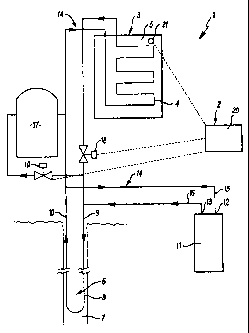
4 Referring initially to Figure 1, a schematic view of an
5 energy storage system 1 is presented, to illustrate an
6 embodiment of the present invention.
7
8 The system 1 comprises a control module 2, which governs
9 the storage and transfer of thermal energy between the'
10 constituent components of the system 1.
11
12 A solar water heating panel 3 is provided, which
13 comprises a tubing 4 containing water to be heated. The
14 tubing 4 is arranged within the panel 3 in a serpentine
fashion to increase the length and surface area of tubing
16 4, and hence amount of water, to be heated. Solar energy
17 impinges on the panel 3, which for exemplary purposes
18 further comprises a blackened plate 5 in thermal contact
19 with the tubing 4. The plate 5 heats up under the
impinging solar energy, and in turn the heat is
21 transferred to the water within the tubing 4.
22
23 When deployed in this way, heating of the water in the
24 solar water heating panel 3 is effected by the thermal
energy collected from sunlight. The sunlight heats up
26 the panel 3 and as a result, thermal energy is
27 transferred from the plate 5 to the water. The heated
28 water can be pumped away and the thermal energy will be
29 replaced by continued thermal energy received from the
sun which will reheat the panel 3. As the water may be
31 circulated, the thermal energy may be carried away from
32 the solar panel to other parts of the system 1.
33
CA 02613231 2007-12-21
WO 2006/136860 _ PCT/GB2006/002349
11
1 A ground loop 6 is provided, in the form of a bore hole 7
2 with an inserted hose package 8 of an appropriate length.
3 The hose package 8 extends to the bottom of the bore hole
4 7 where it loops to extend back up to the surface. It is
envisaged that if necessary a larger length of hose could
6 be accommodated by adopting a coiled, serpentine or
7 helical hose in a shortened borehole. The borehole 7
8 will typically extend to between 60 and 100m in depth.
9 This acts as a thermal energy storage device as the
water, heated as described above, may be pumped to the
11 ground loop 6 where it can reside underground. The
12 ground loop 6 similarly comprises a ground loop input
13 port 9 and a ground loop outlet port 10 formed at either
14 end of the hose package 8.
16 A heat pump 11 is also provided, the heat pump 11
17 comprising a heat pump input port 12 and a heat pump
18 output port 13. The heat pump input port 12 and output
19 port 13 receive the heated water disposed from the solar
panel 3 or from the borehole 7, and is connected to a
21 hose system 14 between them both by means of an input
22 hose 15 and an output hose 16. The hose system 14 joins
23 the solar panel 3 and the ground loop 6 in the borehole
24 7, to which the input 15 and output hoses 16 of the heat
pump 11 are connected. The thermal energy storing water
26 can therefore be circulated amongst the components of the
27 system 1.
28
29 The heat pump 11 is used to provide a heat exchanging
mechanism whereby a house to which the system 1 is
31 deployed may benefit from the thermal energy collected by
32 the water in the system 1. The water within the system 1
33 has been warmed by solar thermal energy in the solar
CA 02613231 2007-12-21
WO 2006/136860 PCT/GB2006/002349
12
1 panel 3, or by thermal energy transferred to or retained
2 by the liquid in the borehole 7.
3
4 The heat exchange mechanism is well known. The warm
liquid is used to heat up a refrigerant within the heat
6 pump 11, which in turn evaporates. The heat pump 11 then
7 compresses the refrigerant which results in an increase
8 in the temperature of the refrigerant. This temperature
9 increase is used to heat up water which is then
transferred to the cylinder 17 or back into the borehole
11 7. In heating the water, the refrigerant condenses and
12 is pumped back to be heated again by incoming water, thus
13 completing the cycle. By way of example only, the heat
14 pump 11 may generate three units of heat for each single
unit of electricity powering the heat pump.
16
17 A first 18 and a second solenoid valve 19 are employed to
18 control the flow of water within the system 1, to control
19 whether the water flows into the borehole 7 or into the
cylinder 17, for example. A "solar controller" 20 is
21 provided which controls the operation of the valves 18,19
22 in response to the temperature of the solar water heating
23 panel 3, as measured by the temperature sensor 21. A
24 number of predetermined conditions, i.e. threshold
temperature values, are set from which the "solar
26 controller" 20 determines the optimum flow of water to
27 optimise energy efficiency.
28
29 The cylinder 17 is analogous to a hot water tank within a
conventional domestic environment, wherein water is
31 heated and then stored in the cylinder 17, ready for use.
32 The cylinder 17 is adapted to receive hot water from the
33 heat pump 11, axid also from the solar water heating panel
CA 02613231 2007-12-21
WO 2006/136860 PCT/GB2006/002349
13
1 3 dependent on the position of the valves 18,19, and
2 store each in a first and a second reservoir
3 respectively.
4
In accordance with safety rules and regulations, a number
6 of safety features (not shown) are also incorporated. A
7 pressure relief valve, typically designed to relieve
8 pressures in excess of 1.5 bar, is provided to prevent
9 excess pressure build up in the hose system.
Furthermore, a temperature relief valve, typically
11 designed to relieve temperatures in excess of 100 C, is
12 provided to prevent overheating of the system, and also
13 prevents water of excessive temperatures being supplied
14 through, for example, the plumbing system of a house.
16 An exemplary mode of operation will now be described in
17 relation to the block diagram illustrated in Figure 2,
18 and with further reference to Figure 1.
19
The values in the following description of operation are
21 for indicative and relative purposes only and are not
22 intended to be limiting.
23
24 The temperature of the solar water heating panel is
constantly monitored 22 by the temperature sensor. The
26 temperature of the water within may be directly
27 determined from the temperature of the solar water
28 heating panel.
29
When the temperature of the solar water heating panel is
31 below 16 C 23, the solar water heating panel produces
CA 02613231 2007-12-21
WO 2006/136860 PCT/GB2006/002349
14
1 water at below 8 C, which will typically not increase the
2 temperature of water stored in the ground loop and
3 therefore the system does nothing 24.
4
When the temperature exceeds 16 C 23, but is below a
6 second threshold value 25 of, say, 48 C, the solar water
7 heating panel produces hot water up to a temperature of
8 30 C 26. This water is pumped directly into the ground
9 loop 27.
11 It is worth noting that typically the temperature will
12 have to remain above any threshold value for, say, 30
13 seconds before any action is performed as a result.
14
If the temperature exceeds 48 C 25, hot water is produced
16 at temperatures of 42 C and above 28. This water is
17 pumped directly to the cylinder 29.
18
19 In the meantime, domestic demand on the water cylinder
may require hot water to be provided 30 in excess of the
21 hot water currently produced directly by the solar water
22 heating panel in which case the water from the ground
23 loop is pumped to the heat pump 31. The heat pump
24 generates hotter water which is then pumped to the
cylinder 32, as long as demand continues.
26
27 Any means, preferably reliant on renewable sources, may
28 be employed to extract energy from the surroundings.
29 Furthermore, any means may be employed to store the
energy.
31
32 Figure 3 illustrates a further embodiment of the present
33 invention which employs a rotary turbine 34 as an
CA 02613231 2007-12-21
WO 2006/136860 PCT/GB2006/002349
1 alternative to the solar heating panel discussed in
2 relation to Figure 1 above. The rotary turbine 34 is
3 used to heat a fluid 35 within a tank 36 by means of
4 three 1kW immersion heating elements 37,38,39. The
5 temperature of the fluid 35 within the tank is measured
6 by a thermostat 40.
7
8 The size of the tank 36 will ideally be matched to the
9 desired output of the heating elements. It is envisaged
10 that the tank would be sized at around two thousand
11 litres per kilowatt output of the heating elements
12 37,38,39.
13
14 The fluid 35 within the tank 36 is heated in a staged
15 process. For example, when the rotary turbine 34 is
16 being driven by a light wind, only the first heating
17 element 37 is powered. As the wind increases in speed,
18 the remaining heating elements, 38 then 39, are driven
19 according to the electrical energy being provided by the
rotary turbine 34. A de-stratification,,pump 41 is
21 attached to the tank 36 in order to redistribute thermal
22 energy in the fluid 35 and prevent stratified layers of
23 temperature. This maximises the energy usage in the tank
24 36.
26 A tank hose 42 is arranged within the tank 36 in a
27 serpentine fashion, and is used to extract thermal energy
28 from the tank 36. A fluid within the tank hose 42, for
29 example glycol, is circulated by a circulation pump 43
and thus moves thermal energy from the tank 36 (as
31 generated and stored by means of fluid 35) to other parts
32 of the system 33.
33
CA 02613231 2007-12-21
WO 2006/136860 PCT/GB2006/002349
16
1 Glycol is selected in this example as it has a low
2 freezing point (preventing freezing in the winter) and a
3 high boiling point (meaning it can work with high
4 temperatures), has favourable thermal conductivity (can
transfer heat with its surroundings) and good specific
6 heat capacity (can store thermal energy). However any
7 suitable fluid with similarly advantageous properties may
8 be used.
9
Two ground loops 44,45 are provided, consisting of bore
11 holes 46,47 each with a respective hose package 48,49 of
12 appropriate length inserted. As above, the ground loops
13 44,45 act as thermal energy storage devices, and will (to
14 continue the example above) be filled with glycol.
A heat pump 50 is also provided, and receives heated
16 glycol from either the tank hose 42 or from the boreholes
17 46,47. As described above, the thermal energy provided
18 to the heat pump in this way allows the heat pump to
19 generated heated water for an external system (not shown)
such as an underfloor heating installation.
21
22 An arrangement of hoses join the heat pump 50, bore holes
23 46,47 and the tank in order to facilitate the movement of
24 thermal energy (by means of the glycol within) amongst
the parts of the system as required. Three motorised
26 valves 51,52,53 (and a by-pass valve 54) determine the
27 flow of thermal energy, and are controlled by a control
28 module 55. The control module 55 also receives
29 temperature information via the thermostat 40 in order to
determine how the thermal energy in the system should be
31 routed.
32
CA 02613231 2007-12-21
WO 2006/136860 PCT/GB2006/002349
17
1 In a particular example, the control module 55 monitors
2 the temperature of the fluid 35 within the tank 36 to
3 determine the most efficient way of using the thermal
4 energy available to generate heated water to the external
system.
6
7 When the temperature of the fluid 35 in the tank 36 is
8 below, say, 102C, the heat pump 50 will operate normally
9 and take thermal energy from the fluid in the ground
loops 44,45 in order to generate hot water in accordance
11 with the heat exchange mechanism described above.
12
13 When the temperature of the fluid 35 in the tank 36 is at
14 a temperature of between, say, 102C and 202C, the heat
pump 50 will use the thermal energy from the fluid 35 in
16 the tank 36 via the glycol circulating in the tank hose
17 42 to generate hot water. Above 202C the thermal energy
18 from the tank will be transferred to the ground loops
19 44,45.
21 It is also envisaged that the system 33 could be adapted
22 to operate without the need for the ground loops 44,45.
23 In fact, it is possible to operate the system 33 without
24 these, instead using the fluid 35 within the tank 36 as
the means of storing thermal energy (as well as
26 generating that energy). In this way the heat pump 50
27 could be connected solely to the tank hose 42 and still
28 generate hot water for an external system.
29
An alternative to the ground loop in the borehole
31 comprises a buried hose, for example a hose buried in the
32 garden of a house in which the energy storage system is
33 to be d-ployed. This hose is typically buried at a depth
CA 02613231 2007-12-21
WO 2006/136860 PCT/GB2006/002349
18
1 of approximately 1 m. The hose has two ends, which serve
2 as an input port and an output port. Water is stored
3 within the hose, which may be circulated. The solar
4 energy stored in the ground may also be used to heat the
water, in which case this type of ground loop may in
6 fact, as an alternative, replace the solar panel.
7
8 It has been shown that the present invention provides a
9 system and a relevant method for more efficient use of
energy, in particular thermal energy used as a renewable
11 energy source. In an exemplary embodiment, the system
12 will heat water in a solar water heating plate to
13 transfer to a hot water cylinder, but below a threshold
14 temperature the heated water will be pumped into the
ground loop. When required, the water from the ground
16 loop can be pumped to the heat pump to generate heat
17 which is transferred to a hot water cylinder.
18
19 The foregoing description of the invention has been
presented for purposes of illustration and description
21 and is not intended to be exhaustive or to limit the
22 invention to the precise form disclosed. The described
23 embodiments were chosen and described in order to best
24 explain the principles of the invention and its practical
application to thereby enable others skilled in the art
26 to best utilise the invention in various embodiments and
27 with various modifications as are suited to the
28 particular use contemplated. Therefore, further
29 modifications or improvements may be incorporated without
departing from the scope of the invention as defined by
31 the appended claims.