Note: Descriptions are shown in the official language in which they were submitted.
CA 02613424 2013-03-25
- 1 -
TOROIDAL RAM ACTUATOR
The present invention relates to a ram actuator that
operates under fluid pressure to produce rotary motion.
Background of the Invention
In fields of engineering rotary motion of an actuator or
mechanism is obtained by the use of a linear acting
lo hydraulic or pneumatic ram acting on a linkage or
mechanical arm about a pivoting axis.
Several problems exist with this means of obtaining rotary
motion. Firstly, the space required to package the open-
close movement of a linear acting ram is often large and
undesirable.
Secondly, the mechanical linkages involved
limit the output rotation angle about the pivoting axis.
Thirdly, the corresponding output torque about the
pivoting axis varies dramatically depending upon the
perpendicular component of force applied by the linear ram
acting about the pivoting axis. And
fourthly there are
undesirable force vectors acting on the pivoting axis and
surrounding components, requiring additional strengthening
of such surrounding components.
The present invention provides a means of producing useful
rotary motion in a compact manner and with a consistent
and potentially high output torque.
Summary of Invention
According to the present invention there is provided a
toroidal ram actuator comprising two part toroidal shaped
cylinders mounted to a first member and a part toroidal
piston reciprocally movable within each cylinder, a free
end of each piston being mounted to a second member, the
first and second members being attached along a toroidal
CA 02613424 2013-03-25
- 2 -
axis so to be relatively pivotable to each other, the
relative movement between the cylinders and pistons
producing rotary motion of the first or second member about
the toroidal axis, wherein the cylinders are axially offset
relative to the toroidal axis and are opposed such that the
pistons bear on opposite sides of the second member.
Brief Description of the Drawings
An embodiment, incorporating all aspects of the invention,
will now be described by way of example only with
reference to the accompanying drawings in which:
Figure la is an isometric view of a toroidal ram actuator
ls in accordance with an embodiment of the present invention,
illustrating a first ram in a fully extended position;
Figure lb is the same view as Figure la but illustrating
the first ram and a second ram at intermediate positions;
Figure lc is the same view as Figure la but illustrating
the second ram in a fully extended position;
Figure 2a is a side elevation of the toroidal ram
actuator;
Figure 2b is a plan view of the toroidal ram actuator
illustrated in Figure 2a;
Figure 2c is a front elevation of the toroidal ram
actuator illustrated in Figure 2a;
Figure 3 is a side sectional view taken at section A-A of
Figure 2b;
Figure 4 is a side sectional view taken at section B-B of
Figure 2b;
CA 02613424 2007-12-24
WO 2007/003000 PCT/AU2006/000931
- 3 -
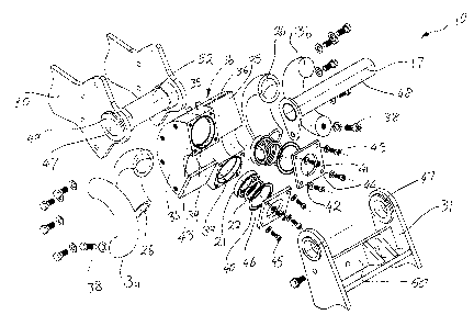
Figure 5 is an exploded isometric view of the toroidal ram
actuator; and
Figure 6 is an exploded isometric view of a second
embodiment of the toroidal ram actuator.
Detailed Description of Preferred Embodiment
In the preferred embodiment of the invention shown in the
drawing, a toroidal ram actuator 10 consists of two
opposing single acting toroidal rams 11. It is understood
however that the principle of the actuator may operate
with a double acting toroidal ram.
In this specification the definition of toroidal is
'geometry of, or resembling a torus' and the definition of
torus is 'a surface or solid formed by rotating a closed
curve, especially a circle, about a line which lies in the
same plane but does not intersect it', for example, a ring
doughnut.
The device consists of two identical, but axially offset
toroidal rams 11 which are inverted, namely rotated by
180 , relative to each other such that a first ram appears
`upside down' to a second ram. The toroidal rams 11 each
comprise a toroidal cylinder 12 and a toroidal piston, or
rod, 13 moveable within the cylinder 12. The cylinders
have an enclosed, internal toroidal surface 15 that is
circular in cross-section.
The cylinders are
approximately semi toroidal, namely approximately half a
revolution in length. A toroidal axis 17 is defined by
the common central axis of the toroidal cylinders. The
toroidal cylinders are rigidly attached to one another
forming a single body referred to as a toroidal cylinder
housing 16.
Each toroidal cylinder is closed at one end, the tail end
CA 02613424 2007-12-24
WO 2007/003000 PCT/AU2006/000931
-4-
19, and the rod 13 is adapted to extend from the other end
which is open and referred to as the open head end 18. An
internal chamber 20 between the head end and tail end is
adapted to hold fluid for actuating the rod hydraulically
or pneumatically. The
fluid used may, for example, be
hydraulic oil or compressed air.
The head end 18 of each cylinder 12 is provided with seal
gland(s) 21 for supporting pressure seal(s) 22. The tail
end 19 of each cylinder is closed off by means of an end
cap 25 attached by welding or otherwise. The housing 16
which houses both cylinders 12 is rigidly attached to a
static member, or fixed link 30. The opening of the head
end 18 of each cylinder 12 allows the insertion of the
toroidal rod 13 which reciprocally extends and retracts
within the cylinder.
In the preferred embodiment of the actuator 10, each
cylinder 12 contains a wear sleeve 26 which acts as a
wearing and guiding surface for each rod inside the
cylinder. The wear sleeve 26 is adapted to evenly guide
and fully support the rod as it extends and retracts to
thereby prevent the rod from rocking or distorting under a
load. The sleeve is made of a wearable material, such as
a composite material, for example nickel filled
polytetrafluoroethylene or similar, to allow the rod to
move smoothly inside the cylinder.
The geometry of the sleeve 26 is similar to that of the
cylinder in which it is housed such that the sleeve 26 can
be inserted into its corresponding cylinder 12 through the
open head end 18. The sleeve 26 is also circular in cross
section. A
clearance between the sleeve and internal
surface of the cylinder 12 compensates for any
misalignments of the rod supported inside the sleeve or if
the rod does not follow a true toroidal path.
The
clearance also facilitates sleeve insertion into the
CA 02613424 2007-12-24
WO 2007/003000 PCT/AU2006/000931
- 5 -
cylinder.
Each rod 13 is a solid member made of steel or other
suitable metal, is a semi-torus in shape and has a
circular cross section. The
rods may be heat
treated/hardened and/or chromed for greater durability and
wear characteristics. The rod 13 is guided and can move
freely within its corresponding cylinder 12. Accordingly,
the rod has one degree of freedom, that being the circular
path the rod partly subscribes about the toroidal axis 17.
A leading end 28 of the rod protrudes from the head end 18
of the cylinder 12 when the rod is fully retracted in the
cylinder. The leading end 28 of each rod is attached to
and acts against a dynamic member, namely a dynamic link
31, which is movable relative to the fixed link 30. The
dynamic link 31 is attached to and rotates about fixed
link 30.
The dynamic link 31 also has one degree of
freedom, that being the same as the rod, namely a part
circular path about the toroidal axis 17.
As the two cylinders 12 are in line but axially offset to
the toroidal axis 17, and inverted relative to each other
so that the head end 18 of the cylinders are diametrically
opposed, the rods 13 act in opposition to each other on
the dynamic link 31.
Each rod 13 is rigidly attached to the dynamic link 31 by
using a bolt 38 or other similar fastener to fasten the
leading end 28 of the rod to a reaction surface 50 on the
dynamic link 31. The first and second rods 13a, 13b are
attached to opposite sides of reaction surface 50.
Reaction surface 50 is machined to allow an accurate
relationship between its opposite surfaces on which the
rods 13a, 13b bear against and the toroidal axis 17 about
which the rods 13 and dynamic link 31 rotate.
CA 02613424 2007-12-24
WO 2007/003000 PCT/AU2006/000931
- 6 -
Accordingly, actuation of a first ram 11a extends a first
rod 13a in a clockwise direction about the toroidal axis
thereby also moving dynamic link 31 in the clockwise
direction, whereas actuation of a second ram 11b extends
the second rod 13b, and hence the dynamic link, in an
anti-clockwise direction.
Ram actuation is alternated
between the first and second rams.
Actuation of the toroidal rams illustrated in the drawings
is carried out by a single acting cylinder in the rams
such that fluid is introduced into the cylinder through
inlet/outlet ports 33a, 33b, to force the rod 13 to move
outwardly of the cylinder under the pressure of increasing
fluid.
During retraction fluid is forced out of the
cylinder through the same inlet/outlet port under the
pressure of the rod being pushed back into the housing by
the force of the opposing rod.
The inlet/outlet ports 33a, 33b are a through hole from
the outside of each cylinder to the inside chamber 20.
Each inlet/outlet port may have welded to it on the
outside, a suitable hydraulic or pneumatic fitting to
allow a corresponding hydraulic or pneumatic hose or
fitting to be attached.
In operation, hydraulic or pneumatic fluid is fed into the
first cylinder 12a via its corresponding inlet/outlet port
33a.
The first cylinder 12a becomes pressurized.
Simultaneously, hydraulic or pneumatic pressure is
relieved from the second cylinder 12b by fluid discharging
from the second cylinder's inlet/outlet port 33b.
Hydraulic or pneumatic fluid is prevented from leaking
beyond the pressure seals 22, which form a positive seal
between each cylinder and its corresponding rod, and 0-
rings provided at the head end.
CA 02613424 2007-12-24
WO 2007/003000 PCT/AU2006/000931
- 7 -
Pressurizing first cylinder 12a forces first rod 13a to
fully extend from cylinder 12a. This step is illustrated
in Figures la, 2a, 2b, 2c, 3 and 4.
Force is then
transferred to the dynamic link 31 to which the leading
end 28 of rod 13a is attached. This in turn produces a
torque about the toroidal axis 17 and causes the dynamic
link 31 to rotate about the toroidal axis in a first
direction. Simultaneously, and in direct proportion, as
rod 13a extends from cylinder 12a, second rod 13b retracts
into cylinder 12b under the force imparted by the first
rod and transferred through dynamic link 31, to which the
second rod is also attached on an opposing side thereof to
the first rod.
Figure 4, which shows section B-B of
Figure 2b, illustrates second rod 13b fully retracted
inside cylinder 12b.
Hydraulic pressure is then relieved from the first
cylinder 12a and pressure is applied to the second
cylinder 12b, which actuates second rod 13b to extend.
Force is transferred to the attached dynamic link in the
opposite direction to that of first rod 13a, and an
opposite torque is created about the toroidal axis 17,
resulting in rotation of the dynamic link 31 in the
opposite direction. Figure lb illustrates dynamic link 31
partially rotated where rods 13a and 13b are partially
extended at an intermediate position.
Figure lc
illustrates link 31 rotated, with first rod 13a fully
retracted and second rod 13b fully extended.
This process is repeated to alternate actuation of the
first and second rams 11a, 11b, to thereby reciprocally
move dynamic link 31 along an arcuate path centred at
toroidal axis 17.
A removable cover may be provided over the toroidal ram
actuator 10 to cover the moving rods 13 and prohibit these
from being damaged.
CA 02613424 2007-12-24
WO 2007/003000 PCT/AU2006/000931
- 8 -
The cylinder housing llb in this embodiment is constructed
from a number of separately machined and fabricated
components which define the two opposing cylinders 12a,
12b. The housing parts comprise a central part 35, two
outer parts 36, one to either side of central part 35, and
two cylinder end caps 25 which close off the tail end 19
of the cylinders 12. The end cap 25 consists of a flat
metal plate welded to the tail end of each cylinder.
The central part 35 is approximately half a revolution of
a solid metal ring of rectangular section, that is
machined on each side to form a semi toroidal shaped
channel that is semi circular in cross section.
The
central part forms half of the internal surface of each
cylinder.
The outer parts are formed from machining mating
components to complete the cylinder formation on either
side of the central part. The outer parts 36 are aligned
and welded concentrically to each side of the said central
part 35 to form a complete pair of axially offset and
inverted cylinders. Aligning grooves may be machined into
the mating surfaces to assist in alignment.
Another alternative method of constructing each said
toroidal cylinder housing is to machine the internal
toroidal surface from a solid metal disc using a special
boring tool and boring machine.
The boring tool and
machine would be set up so that the tool rotates about the
said common toroidal axis and cuts the internal toroidal
surface in which the said composite channel and said
toroidal rod is housed.
Machined into the head end 18 of each cylinder 12 is a
cylindrical recess 39 of diameter greater than that of the
internal cross-sectional diameter of the cylinder and
CA 02613424 2007-12-24
WO 2007/003000 PCT/AU2006/000931
- 9 -
facing inwardly of the cylinder. This recess 39 forms the
recess in which the seal gland 21 is housed, which in turn
supports the pressure seal 22. The external end face of
the head end 18 is also machined to form a groove to
receive a face seal such as an 0-ring 40 or similar. The
0-ring 40 seals a gland cover 41 against the cylinder 12.
A second 0-ring 46 sits in a groove in the seal gland to
seal the gland against the end cover. Drilled and tapped
holes 43 machined into the end face of the cylinder's head
end 18 allow for fixing of the gland cover 41 to the head
end 18 by way of fasteners 45.
The seal gland 21 is a cylindrical ring made of metal
and/or composite material that sits, or floats', in the
cylindrical recess 39 between the rod and the cylinder. A
clearance between seal gland 21 and cylinder 12 serves a
similar function to the clearance between the wear sleeve
26 and cylinder 12 in that the clearance allows for
misalignment during movement of the rod. The depth of the
cylindrical ring is equal to that of the said cylindrical
recess 39 such that the seal gland sits flush with the
external end face of the head end 18. The seal gland 21
extends into the chamber so that the pressure seal 22
contacts the rod.
The seal gland may optionally be made of a composite
material similar to that of the composite sleeve 26 with
material properties that give the gland better wear
characteristics.
Such composite materials have low
porosity which provides good sealing properties.
The seal gland cover 41 illustrated in the figures is a
machined flat metal plate with a cylindrical opening 42 in
the centre through which rod 13 extends.
Around the
periphery of the plate are holes 44 which align with the
drilled and tapped holes 43 on the face of the head end 18
of each cylinder. Fasteners such as cap screws are used
CA 02613424 2007-12-24
WO 2007/003000 PCT/AU2006/000931
- 10 -
to attach the seal gland cover 41 to the head end 18 of
each cylinder 12. The gland cover seals against the 0-
rings 40 and 46 preventing hydraulic or pneumatic fluid
escaping from the cylinder chamber 20. A wiper seal (not
shown) could be attached or housed on the outside of the
seal gland cover and concentric with the opening 42 and
would bear against the rod 13 to prevent dirt/debris from
entering the seal gland 21.
The pressure seals 22 and wiper seals may be standard
linear ram seals, have a geometry that adapts to the
arcuate surface of the toroidal shaped rods, or may be
custom made seals having an arcuate sealing surface to
match the arcuate surface of the rods. One example of a
suitable pressure seal is U-seal having a depth that will
not compromise seal performance and durability in sealing
against a toroidal shaped rod.
The pressure and wiper
seals may be made from a polyurethane/rubber based
material or a similar material/s to that used in standard
hydraulic or pneumatic rod seals.
A number of drilled and tapped holes in the side of
housing 16 are used to attach the cylinder housing to the
fixed link 30 using fasteners 45 such as bolts or cap
screws.
In the first embodiment of the actuator illustrated in
Figures 1-5 the fixed link 30 includes through holes 47
that align with the toroidal axis 17 to support a pivoting
pin 48 used to attach the fixed link 30 to dynamic link
31. Pivoting pin 48 extends through similar holes 47 in
dynamic link 31. Bearings 49 and/or bushes 52 mounted in
the through holes 47 allow dynamic link 31 to rotate
relative to fixed link 30.
A pivoting pin plate 53 attached to the end of pin 48 and
fixed, in Figures la-lc, to the dynamic link 31, rigidly
CA 02613424 2007-12-24
WO 2007/003000 PCT/AU2006/000931
- 11 -
fixes the pin to the dynamic link or the fixed link, as
desired, to prevent undesired rotation of the pin 48.
The abovedescribed embodiment which is illustrated in
Figures 1-5 is used to drive a member, such as the dynamic
link 31. Figure 6 illustrates a second embodiment which
is a variation on the actuator of the first embodiment in
that it is used to produce rotary output motion of the
pivoting pin 48 to harness the reciprocating shaft rotary
motion of the pin 48. The
pivoting pin 48 in this
embodiment takes the role of an output shaft 58 and the
dynamic link 31 takes on the role of a torque arm 51.
This variation may only be suitable for lower torque
output applications such as pneumatic applications due to
limitations in the torque transmitting capabilities of the
output shaft.
Figure 6 shows that cylinder housing 16 comprises an
integrated solid plate 54 on each side thereof. The fixed
link in the second embodiment is not illustrated in Figure
6. A through hole 47 concentric with the toroidal axis 17
supports output shaft 58, bearing 49 and bushes 52.
The torque arm 51 is similar in design to the dynamic link
31, but has no protruding length beyond the point of
attachment of the rods 17 because there is no need for the
torque arm to drive a member but instead functions to
transmit the torque to the said output shaft.
The design of the bushes 49 located in holes 47 is such
that the output shaft which passes through the bushes 49
is mechanically linked to the torque arm 51 such that when
the torque arm is rotated, the output shaft also rotates.
The mechanical link may be in the form of a mechanical
attachment such as bushes with two internal flats on the
side and corresponding flats machined on the output shaft
as illustrated in Figure 6, or may involve more complex
CA 02613424 2007-12-24
WO 2007/003000 PCT/AU2006/000931
- 12 -
geometry such as an internal spline on the bushes and a
corresponding external spline on the said output shaft.
Any other form of matching geometry to mechanically link
the said torque arm to the said output shaft may be used.
As discussed above, the toroidal ram actuator may use
double acting toroidal ram/s in replacement of the two
opposing single acting toroidal rams. The single acting
toroidal ram only forces the rod outwardly of the cylinder
and relies on an external force to push the rod to
retract. One double acting ram actuator could be used to
actuate both the extension of the rod and its retraction.
Hence, only a single, double acting toroidal ram would be
required to produce rotation of the output shaft or
dynamic link in both directions, replacing two single
acting rams.
Accordingly, the actuator 10 may consist of two single
acting toroidal rams, or a combination of any number of
single or double acting rams axially aligned, offset
and/or inverted. Single acting toroidal rams are
preferably grouped in opposing pairs.
The proposed actuator 10 defines each said toroidal
cylinder and corresponding said toroidal rod as being
circular in cross section. However the toroidal surface
of both the cylinder 12 and the rod 13 may be of a cross
section that resembles something other than a circle. For
example, an elliptical toroidal surface may be used as
well as custom elliptical pressure and wiper seals.
The above metal components of the toroidal ram actuator 10
have been described as being formed by machining. It is
understood, however, that the components may be casted in
accurate cast mouldings and then machined as required.
Alternatively, it may be suitable in some lighter
CA 02613424 2013-03-25
- 13 -
applications, such as in a pneumatic actuator which may
only requires small output torques and hence small loads,
to replace the metal components with a suitable plastic
material. The plastic
parts may be moulded or machined
from raw materials. The overall relative geometry of the
toroidal ram actuator in plastic would be similar to that
of the above described machined and welded embodiments.
The size of the toroidal ram actuator varies according to
the application in which it is used. For example, a large
actuator would be required in applications such as
actuating the arms of excavators, cranes and other heavy
earth moving equipment, mining equipment or agricultural
equipment. Smaller
versions of the actuator may be used
in manufacturing processes where pneumatic production
equipment is used or the like.
Essentially, the present
toroidal ram actuator can replace linear ram actuators
currently used in any application where rotary motion is
to be produced.