Note: Descriptions are shown in the official language in which they were submitted.
CA 02613801 2012-09-13
74040-22
SPIRAL GAS SEPARATOR
FIELD OF THE INVENTION
This invention relates to an arrangement for
separating gas from liquids. In particular, though not
exclusively, the invention relates to a gas separator intended
for use in separating gas from oil in a downhole formation.
BACKGROUND OF THE INVENTION
The terms "sub-surface formation" and "downhole
formation" typically refer to the rock formation around a bore
which has been drilled into the ground. The borehole provides
a path for hydrocarbons, such as oil and gas, in the rock
formation to be brought to the surface. Sub-surface formations
from which hydrocarbons are produced, typically contain a fluid
which includes liquid and gas mixed together. The liquid from
the downhole formation will normally require pumping to bring
it from the downhole formation to the surface. Pumps used for
pumping the fluid from the downhole formation to the surface,
such as progressing cavity pumps, piston pumps or electric
submersible pumps, operate more efficiently if there is no gas
in the fluid being pumped. Also, the presence of gas in the
fluid being pumped can damage the pump, through heat
generation, cavitation or gas absorption.
There are various devices known for separating gas
from liquid in a downhole application. See, for example,
U.S. Patent No. 5,902,378 to Obrejanu.
Typically, the more gas which can be eliminated from
the fluid, the better the operation of the pump.
1
CA 02613801 2007-12-07
74040-22
SUMMARY OF THE INVENTION
In a broad aspect, the invention provides an
apparatus for separating components of a fluid containing
liquid and gas, the apparatus comprising: a housing
comprising therein at least one elongate channel; the at
least one elongate channel comprising an inlet end, an
outlet end and rounded walls enabling the fluid flowing
through the channel to flow substantially free of turbulent
flow; the at least one elongate channel defining a spiral
path through the housing and acting to separate the fluid
flowing through the channel into a gas-depleted outer
portion and a liquid-depleted inner portion; and a liquid
outlet port for the gas-depleted outer portion and a gas
outlet port for the liquid-depleted inner portion.
In some embodiments, the at least one channel has
a substantially round cross-section.
In some embodiments, the at least one channel
comprises two channels.
In some embodiments, the at least one channel has
a length that is approximately 3 x II times the mean diameter
of the spiral passage.
In some embodiments, the housing further comprises
a mixing chamber in fluid communication with the inlet end
of the channel.
In some embodiments, the mixing chamber has a
chamber inlet directed toward an impact surface to
facilitate breaking up of clumps and further mixing of the
fluid.
In some embodiments, the direction of the chamber
inlet is not aligned with the inlet end of the channel.
2
CA 02613801 2007-12-07
=
74040-22
In some embodiments, the direction of the chamber
inlet is angled at approximately 90 to a direction of the
channel at the inlet end.
In some embodiments, the chamber inlet is in an
axial end of the housing.
In some embodiments, the apparatus further
comprises a chamber at the outlet end of the channel, the
chamber comprising the liquid and gas outlet ports and
configured to direct the gas-depleted outer portion to the
liquid outlet port and the liquid-depleted inner portion to
the gas outlet port; wherein the chamber further comprises a
guide member extending into the chamber adjacent to the
outlet end of the at least one channel to direct the liquid
depleted inner portion to the gas outlet port; and wherein
the gas outlet port is closer to the guide member than the
liquid outlet port.
In some embodiments, the gas outlet port comprises
a tube projecting into the chamber and axially aligned with
a free end of the guide member.
In some embodiments, the gas outlet port is spaced
approximately 1 inch from the free end of the guide member.
In another broad aspect, the invention provides a
method for separation of components of a mixture containing
liquid and gas, the method comprising: drawing a flow of the
mixture into a separator; advancing the flow in the
separator in a rounded wall spiral path with sufficient
angular momentum to effect ordering of the flow and at least
partial separation of the flow into an inner liquid-depleted
gaseous portion and a outer gas-depleted liquid portion;
directing the inner liquid-depleted gaseous portion to a gas
3
CA 02613801 2007-12-07
=
74040-22
outlet port; and directing the outer gas-depleted liquid
portion to a liquid outlet port.
In some embodiments, the drawing of the flow of
the mixture into the separator includes directing the flow
against an impact surface for breaking clumps and further
mixing the mixture.
In some embodiments, the method further comprises
passing the mixture from the spiral path into a chamber and
drawing off the inner liquid-depleted gaseous portion before
drawing off the outer gas-depleted liquid portion; passing
the mixture from the spiral path into an exhaust chamber at
reduced turbulence to maintain the separation of the
portions; and drawing off the liquid portion.
In another broad aspect, the invention provides an
apparatus for separating components of a fluid containing
liquid and gas, the apparatus comprising: a housing
comprising therein at least one elongate channel; the at
least one elongate channel comprising an inlet end, an
outlet end; a mixing chamber in fluid communication with the
inlet end of the channel, the mixing chamber having a
chamber inlet directed toward a impact surface to facilitate
breaking up of clumps and further mixing of the fluid; the
at least one elongate channel defining a spiral path through
the housing and acting to separate the fluid flowing through
the channel into a gas-depleted outer portion and a liquid-
depleted inner portion; and a liquid outlet port for the
gas-depleted outer portion and a gas outlet port for the
liquid-depleted inner portion.
In another broad aspect, the invention provides an
apparatus for separating components of a fluid containing
liquid and gas, the apparatus comprising: a housing
4
CA 02613801 2012-09-13
74040-22
comprising therein at least one elongate channel; the at least
one elongate channel comprising an inlet end, an outlet end;
the at least one elongate channel defining a spiral path
through the housing and acting to separate the fluid flowing
through the channel into a gas-depleted outer portion and a
liquid-depleted inner portion; a chamber at the outlet end of
the channel, the chamber comprising a liquid outlet port for
the gas-depleted outer portion and a gas outlet port for the
liquid-depleted inner portion; the chamber further comprises a
guide member extending into the chamber adjacent to the outlet
end of the at least one channel to direct the liquid depleted
inner portion to the gas outlet port wherein the gas outlet
port is closer to the channel outlet end than the liquid outlet
port.
In a further broad aspect, the invention provides an
apparatus for separating components of a fluid containing
liquid and gas, the apparatus comprising: a housing comprising
therein at least one elongate channel; the at least one
elongate channel comprising an inlet end, an outlet end and a
cross-section of smoothly rounded walls and corners enabling
the fluid flowing through the channel to flow substantially
free of turbulent flow; the at least one elongate channel
defining a spiral path through the housing and acting to
separate the fluid flowing through the at least one elongate
channel into a gas-depleted outer portion and a liquid-depleted
inner portion; and a liquid outlet port for the gas-depleted
outer portion and a gas outlet port for the liquid-depleted
inner portion.
In still a further broad aspect, the invention
provides a method for separation of components of a mixture
5
CA 02613801 2012-09-13
74040-22
containing liquid and gas, the method comprising: drawing a
flow of the mixture into a separator; advancing the flow in the
separator in a spiral path, having a cross-section of smoothly
rounded walls and corners, with sufficient angular momentum to
effect ordering of the flow and at least partial separation of
the flow into an inner liquid-depleted gaseous portion and a
outer gas-depleted liquid portion; directing the inner liquid-
depleted gaseous portion to a gas outlet port; and directing
the outer gas-depleted liquid portion to a liquid outlet port.
In another broad aspect, the invention provides an
apparatus for separating components of a fluid containing
liquid and gas, the apparatus comprising: a housing comprising
therein at least one elongate channel; the at least one
elongate channel comprising an inlet end, an outlet end; a
mixing chamber in fluid communication with the inlet end of the
at least one elongate channel, the mixing chamber having a
mixing chamber inlet directed toward an impact surface wherein
fluid entering the mixing chamber is directed to impact on the
impact surface to facilitate breaking up of clumps and further
mixing of the fluid; the at least one elongate channel defining
a spiral path through the housing and acting to separate the
fluid flowing through the at least one elongate channel into a
gas-depleted outer portion and a liquid-depleted inner portion;
and a liquid outlet port for the gas-depleted outer portion and
a gas outlet port for the liquid-depleted inner portion.
In yet another broad aspect, the invention provides
an apparatus for separating components of a fluid containing
liquid and gas, the apparatus comprising: a housing comprising
therein at least one elongate channel; the at least one
elongate channel comprising an inlet end, an outlet end; the at
5a
CA 02613801 2012-09-13
74040-22
least one elongate channel defining a spiral path through the
housing and acting to separate the fluid flowing through the at
least one elongate channel into a gas-depleted outer portion
and a liquid-depleted inner portion; an exhaust chamber at the
outlet end of the at least one elongate channel, the exhaust
chamber comprising a liquid outlet port for the gas-depleted
outer portion and a gas outlet port for the liquid-depleted
inner portion; the exhaust chamber further comprises a guide
member extending into the exhaust chamber from a direction of
and adjacent to the outlet end of the at least one elongate
channel, the guide member having an outer surface tapering to
direct the liquid depleted inner portion to the gas outlet port
wherein the gas outlet port is spaced from a free end of the
guide member and is closer to the at least one elongate.
In some embodiments, the guide member is cone shaped.
BREIF DESCRIPTION OF THE DRAWINGS
Figure 1 is a downhole end view of a gas separator
according to an embodiment of the invention;
Figure 2 is sectional view of the gas separator of
Figure 1 taken along line AA but with the main sub not shown as
sectioned;
Figure 3 is a sectional view of the gas separator of
Figure 1 taken along line AA with the main sub shown as
sectioned;
Figure 4 is a sectional view of the gas separator of
Figure 2 taken along line CC;
Figure 5 is a sectional view of the gas separator of
Figure 2 taken along line DD;
5b
CA 02613801 2007-12-07
74040-22
Figure 6 is a hidden line view of the gas
separator of Figure 1;
Figure 7 is a perspective view of the main sub of
the gas separator of Figure 1 with a spiral passage
depicted; and
Figure 8 is flow velocity profile for a second
embodiment of the invention which has two spiral passages.
DETAILED DESCRIPTION OF THE PREFERRED EMBODIMENT
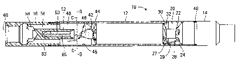
A separator 10 is shown in Figures 1 to 5. The
separator 10 includes a housing 12. A channel 34 extends
through the housing 12. The channel 34 defines a spiral path
through the housing which separates the fluid flowing
through the channel into a gas-depleted outer portion and a
liquid-depleted inner portion. The separator also includes
a liquid outlet port for the gas-depleted outer portion and
a gas outlet port for the liquid-depleted inner portion.
The channel 34 may have rounded walls enabling the fluid
flowing through the channel 34 to flow substantially free of
turbulent flow. The separator may also include a mixing
chamber 20 in fluid communication with the inlet end of the
channel.
The separator 10 may also include a chamber 46 at
the outlet end of the channel 34. The chamber 46 can
include the liquid and gas outlet ports and a guide member
for guiding the liquid-depleted inner portion. The gas
outlet port can be closer to the guide member than the
liquid outlet port.
Turning to the drawings in detail, the main
components of the separator 10 in the embodiment of Figures
1 to 5 include the tubular housing 12, a main sub 14 and a
6
CA 02613801 2007-12-07
74040-22
top sub 16. These components will be described in turn from
the normally downhole end upward.
The main sub 14 is depicted in cross-section in
Figure 3. The normally downhole end of the main sub 14 has
a separator inlet 18. The separator inlet 18, in this
example, is a tubular channel. In this embodiment, the
separator inlet 18 is in an axial longitudinal end of the
separator 10, rather than, for example, extending through
the tubular sides of the main sub 14. The separator inlet
18 may define the bottom of a production string or other
components may be attached below the separator inlet.
Next in line, in this example, from the downhole
end of the main sub 14 is the mixing chamber 20. In this
embodiment, the mixing chamber 20 is a ring shaped chamber
formed between the housing 12 and a narrow portion of the
main sub 14. The mixing chamber 20 has a tubular outside
face 26 defined by an inside surface of the tubular housing
12. The mixing chamber also has axial end faces 24 and 30
which are angled towards the outside face 26.
The separator inlet 18, is connected to the mixing
chamber 20 through angled inlet ports 22. The inlet ports
22 connect to the mixing chamber 20 through the face 24.
The face 24 is angled and the inlet ports are directed so
that fluid exiting the inlet ports 22 is directed to impact
the face 26 of the housing 12. This impact helps to break
up clumps of heavy oil or solids and homogenize the mixture
of phases before the separation process starts. In this
embodiment, the inlet ports have a spiral direction which is
counter to the spiral direction of the channels 34, also to
increase mixing. The extreme turbulence induced by the
continuous inflow of fluids through the inlet ports and the
impact of the fluids with the inside of the housing 12 and
7
CA 02613801 2007-12-07
74040-22
the angled face 30, creates a shearing effect that helps
free the gas trapped in the heavy oil clumps. An exemplary
fluid path 29 is shown in Figure 2. It will be appreciated
that the specific angles shown in the figures are not
essential. For example, the face 24 may be straight if the
inlet ports 22 are directed towards the face 26. Any
configuration which causes the fluid exiting the inlet ports
22 to impact against a surface may be used or the feature of
using an impact surface may be eliminated.
Axially opposite the angled face 24 of the mixing
chamber 20 is the face 30. In this embodiment, the face 30
is angled in the opposite direction to the face 24. The
particular angle is not essential and may be eliminated. In
this embodiment, the angle is such that fluid deflected by
the face 26 is deflected by the face 26 towards the angled
face 30.
The next component is the channel 34. As
previously noted, the elongate channel 34 defines a spiral
or helix passage through the separator 10. The passage is
shown schematically in Figures 6 and 7. In the embodiments
depicted in the figures, the spiral channel 34 is shown as
having a circular cross-section. The circular cross-section
enables a smooth flow pattern for fluid flowing through the
channel 34. The cross-section, however, does not need to be
circular. Any smooth wall shape without sharp corners, such
as an oval or other shapes with smoothly rounded corners,
may be used. This is in contrast to having passages defined
by an auger in a housing as in U.S. Patent No. 5,902,378
referenced above.
In this embodiment, the portion of the gas
separator 10 through which the spiral channel 34 is defined
is part of the main sub 14. The housing 12 extends over
8
CA 02613801 2007-12-07
74040-22
this portion of the main sub 14 and is connected to the main
sub 14 at a connection 40. The connection 40 may, for
example, be a threaded or a press-fit connection.
It will be appreciated that these elements may be
formed in different ways. For example, the main sub 14 may
be comprised of several different parts and the portion of
the separator 10 through which the spiral channel 34 is
defined may not have a surrounding housing 12. The spiral
channel 34 may be machined through a single part as depicted
in the figures or may, for example, be machined on the
outside and inside of the axially mating parts which
together define the channel 34.
Inlets 32 to the spiral channels 34 are defined
through the face 30. Figures 1 to 7 depict a single spiral
channel 34. However, it will be appreciated that more than
one spiral channel may be present. For example, figure 8
depicts two spiral channels.
The orientation of the components of the separator
may be used to improve mixing. Figure 6 shows an angle 36
between the longitudinal axis of the separator 10 and the
direction of entry of the mixing chamber inlet ports 22 into
the mixing chamber 20. In this embodiment, the angle 36 is
35 degrees. Figure 6 further shows an angle 38 between the
direction of the inlet ports 22 and the direction of the
inlets 32 to the spiral channels 34. In this embodiment, an
angle of 90 degrees is depicted. These angles are not
essential. The differing directions of the inlet ports 22
and the inlets 32 allow for increased mixing in the mixing
chamber 20. The face 26 may also have a shoulder 27 upon
which fluid may impact.
9
CA 02613801 2007-12-07
74040-22
Maximising the mixing or agitation is helpful to
break up clumps of material. Breaking up the clumps of
solid particles helps to prevent the solids from disturbing
the organised flow through the spiral passages. Breaking up
of clumps or droplets of very viscous heavy oil will cause
the "trapped" or attached gas to be released and more easily
separated from the liquid. Otherwise, the gas trapped by
high surface tension of the very viscous heavy oil may be
washed through, with the liquid phase, reducing the
efficiency of the gas separation. The freeing of the gas is
also enhanced by the change in the fluid flow velocity in
going from the small inlet ports 22 to the larger mixing
chamber 20, by change in direction as the fluid impacts the
face 26, by the change in direction from oppositely angled
inlet ports 22 to the inlets 32, and by the change in
pressure in the larger volume of the mixing chamber 20
compared with the inlet ports 22. The mixing chamber
transforms the natural influx of gas, liquids and solids
into a homogenous mixture that will flow more easily through
the spiral passages and will be more easily organised in
separate layers by centrifugal forces. However, the mixing
chamber may be eliminated.
In this embodiment, the main sub 14 terminates as
a guide cone 48. The guide cone 48 is centered axially on
the end of the main sub 14 opposite the inlet 18. The
guide cone has initially straight sides which taper to a
cone with a rounded end. Other embodiments which eliminate
the cone or provide a cone or projection of other shapes may
be utilised.
The exhaust chamber 46 is the next component
following the channel 34. The exhaust chamber is defined by
the main sub 14 on one end, the inside surface of the
housing 12 defining an outside face 45, and the top sub 16
CA 02613801 2007-12-07
74040-22
at the other end. The top sub 16 and the housing 12 are
connected by a connection 50, for example, by a threaded
connection or other manner. The guide cone 48 projects into
the exhaust chamber 46. The top sub 16 includes a gas
exhaust nipple 52.
The spiral channel 34 has an outlet 42 into the
chamber 46. In this embodiment, the spiral channel 34 exits
the main sub 14 through a face 44. In this embodiment the
face 44 is angled toward an outside face 45 of the chamber
46. The face 44 need not be angled. For example, the face
44 may be perpendicular to the outside face 45 of the
chamber 46. The angling of the face 44 helps to maintain
the separation of the gas and liquid phases of a fluid
exiting the spiral channel 34, by reducing the potential
creation of turbulence in the liquid stream.
The face 44 in this embodiment is angled at GO
degrees to the face 30 but this relationship is not
necessary.
The gas exhaust nipple 52 extends into the chamber
46 and is aligned with the guide cone 48. In this
embodiment, the gas exhaust nipple 52 is cylindrical with a
cylindrical channel 53 defined therethrough. The channel 53
has a flared entrance from the chamber 46. The spacing
between the guide cone 48 and the gas exhaust nipple 52 is
chosen to allow a maximum amount of gas to flow from the
guide cone 48 into the gas exhaust nipple 52. In some
embodiments, the inlet of the gas exhaust nipple 52 has a
diameter of 1% inches, the spacing between the gas exhaust
nipple and the guide cone 48 is 1 inch and the main sub has
a diameter of 5% inches. The spacing between the guide cone
and the exhaust gas nipple may also, for example, be between
% inch and 1% inches.
11
CA 02613801 2007-12-07
74040-22
The channel 53 connects to a gas outlet 54. The
gas outlet 54 provides an exit through a side of the
separator 10 as best seen in figure 6.
Surrounding the gas exhaust nipple 52 are
relatively large diameter liquid exhaust passages or
channels 56. The liquid exhaust passages 56 may, for
example, be a series of channels or a single channel. The
liquid passage 56 terminates in liquid outlets 58 which
connect to the main liquid outlet 60. The liquid can
therefore exit the separator 10 in an axially longitudinal
direction. In contrast to the gas, which exits from the
side of the separator 10. Figure 2 depicts an exemplary
liquid path 63 and an exemplary gas path 65.
The positioning and shape of the nipple 52, the
cone 48, the passages 56 and the other elements of the
chamber 46 may be varied or eliminated within the scope of
the invention. Other configurations of the invention may
eliminate the chamber 46 and connect the channel 34 to the
respective gas and liquid outlets.
In an exemplary use, the separator 10 is connected
at the bottom of a downhole assembly with a pump, such as a
progressing cavity pump, installed above the separator 10.
The liquid outlet 60 is connected to the inlet of the pump.
Suction is then applied by the pump. The suction pulls
fluid from the downhole into the separator inlet 18. The
fluid will contain gas, liquid and possibly solids. The
suction further pulls the fluid through the mixing chamber
inlet ports 22. The mixing chamber 20 also acts as an
expansion chamber since it has a volume greater than that of
the inlet ports 22. The direction of the mixing chamber
inlet ports 22 causes the fluid to impact against the face
26 of the mixing chamber 20. The turbulence caused by the
12
CA 02613801 2007-12-07
74040-22
fluid flowing into the mixing chamber 20 and the impact of
the fluid on the inside face 26 creates a shearing effect
that causes clumps to be broken up and the fluid to be more
homogeneously mixed. The suction then pulls the fluid
through the inlets 32 into the spiral channel 34 (see the
exemplary liquid path 29).
Centrifugal forces created by the spiral path
cause the fluid to separate as it flows through the spiral
channel 34. The gas will flow along an inside face 35 of
the spiral channel 34 and the liquid, which is more dense
than the gas, will flow along an outside face 37, thus
creating a gas-depleted outer portion and a liquid-depleted
inner portion. The smoothly curved walls of the spiral
channel 34, means that the fluid flow is more organised.
This minimises turbulence, which would cause re-mixing, and
helps maximise the separation of the components of the fluid
into the gas component and the liquid component.
The fluid then exits the spiral channel 34, at the
outlet 42 into the exhaust chamber 46. The function of the
exhaust chamber 46 is to maintain the separate flow of the
liquid and gas phases until the gas phase is channelled into
the gas exhaust port, before it has a chance to get mixed
back into the liquid flow. The close (for example, 1 inch)
spacing between the end of the cone and the gas exhaust
nipple aids in channelling the gas phase. The positioning
of the gas exhaust port or nipple 52 closer to the outlet 42
than the liquid exhaust channels 56 also helps maintain the
separation. The gas follows the guide cone 48 and flows
into the channel 53 of the gas nipple 52, into the gas
outlet 54 and thus out through the side of the separator 10
(see the exemplary gas path 65). The liquid is pulled by
the suction to flow along the sides 45 of the chamber 46 and
out through the liquid exhaust passages 56 (see the
13
CA 02613801 2007-12-07
=
74040-22
exemplary liquid path 63), then through the liquid outlet
ports 58 and finally through the outlet 60 and into the pump
(not shown).
Turning to Figure 8, Figure 8 depicts a flow
simulation which shows how the gas and liquid phases of the
fluid are separated. The dark shaded gas portions 62
follows the guide cone 48 and exit through the channel 53 of
the gas exhaust nipple 52 and the outlet port 54. The light
shaded liquid portion 64 follows the outer surface of the
chamber 46 and exits through the liquid outlet 60.
The profile of the fluid 66 through the spiral
channel shows that in this embodiment, a homogenous mixture
enters the spiral passages and is quickly accelerated
(within the first turn, as seen in Figure 8) to a maximum
velocity. The length of the spiral passage is designed to
allow enough time for the separation of the phases and for
the layers of different densities to be organised, before
exiting the spiral passages into the exhaust chamber. The
length of the spiral passages may be approximately 3 x n
times the mean diameter of the spiral passage with the
minimum length being about 2 x 7r times the mean diameter of
the spiral gas passage. Figure 8 also shows the mixture 68
as mixed by the configuration of a mixing chamber.
In contrast to previous technologies, that used
"open channels" defined, for example, by an auger in a
tubular housing to guide the mixture through an elongated
angular separation chamber, in an angular path, the present
embodiment eliminates the turbulence caused by the sharp
edges of such a flow channel. The turbulent flow through
such open channels causes some of the free gas to be mixed
back into the liquid flow, reducing the efficiency of the
gas liquid separation. The flow of fluids through the
14
CA 02613801 2007-12-07
74040-22
smooth walled spiral passage of the present invention is
less turbulent and will allow for a more organised flow
pattern of the separated phases and ensures that the
separated phases flow in distinct layers in a smooth pattern
and will not be mixed again, thus increasing the separation
efficiency.
The relative position of the gas and liquid
outlets also can enable improved separation. The use of a
separate mixing and/or expansion chamber can also improve
separation.
Numerous modifications and variations of the
present invention are possible in light of the above
teachings. It is therefore to be understood that within the
scope of the appended claims, the invention may be practised
otherwise than as specifically described herein.