Language selection

Search

Patent 2614040 Summary

Third-party information liability

Some of the information on this Web page has been provided by external sources. The Government of Canada is not responsible for the accuracy, reliability or currency of the information supplied by external sources. Users wishing to rely upon this information should consult directly with the source of the information. Content provided by external sources is not subject to official languages, privacy and accessibility requirements.

Claims and Abstract availability

Any discrepancies in the text and image of the Claims and Abstract are due to differing posting times. Text of the Claims and Abstract are posted:

  • At the time the application is open to public inspection;
  • At the time of issue of the patent (grant).
(12) Patent: (11) CA 2614040
(54) English Title: CONVEYING DEVICE
(54) French Title: DISPOSITIF DE TRANSPORT
Status: Granted and Issued
Bibliographic Data
(51) International Patent Classification (IPC):
  • B65G 15/64 (2006.01)
  • B65G 39/16 (2006.01)
  • B65H 23/038 (2006.01)
(72) Inventors :
  • GRABAU, THOMAS (Germany)
(73) Owners :
  • NORDISCHER MASCHINENBAU RUD. BAADER GMBH + CO. KG
(71) Applicants :
  • NORDISCHER MASCHINENBAU RUD. BAADER GMBH + CO. KG (Germany)
(74) Agent: ROBIC AGENCE PI S.E.C./ROBIC IP AGENCY LP
(74) Associate agent:
(45) Issued: 2012-05-15
(86) PCT Filing Date: 2006-05-12
(87) Open to Public Inspection: 2007-01-18
Examination requested: 2008-04-11
Availability of licence: N/A
Dedicated to the Public: N/A
(25) Language of filing: English

Patent Cooperation Treaty (PCT): Yes
(86) PCT Filing Number: PCT/EP2006/004824
(87) International Publication Number: WO 2007006365
(85) National Entry: 2008-01-03

(30) Application Priority Data:
Application No. Country/Territory Date
10 2005 032 752.4 (Germany) 2005-07-09

Abstracts

English Abstract


The invention relates to a conveying device substantially comprising an
endless conveying element (11) which is guided across several deflecting
elements (12) and is provided with a conveying sector (16) and a redirecting
sector (17). The conveying sector (16) defines a conveying plane E. The
conveying device further comprises a drive unit (13) for the conveying element
(11) as well as elements (14) for centering the conveying element (11). The
inventive conveying device is characterized in that at least the deflecting
elements (12a, 12b) located at opposite ends of the conveying sector (16) are
embodied as elements (14) which have an inward-oriented shape and are used for
centering the conveying element (11) perpendicular to the direction of travel
T.


French Abstract

L'invention concerne un dispositif de transport qui comprend principalement un élément de transport sans fin (11) guidé par l'intermédiaire de plusieurs éléments de renvoi (12) et pourvu d'un secteur de transport (16) et d'un secteur de retour (17), ledit secteur de transport (16) définissant un plan de transport (E), un entraînement (13) pour ledit élément de transport (11) ainsi que des éléments (14) destinés à centrer l'élément de transport (11). Ce dispositif de transport se caractérise en ce qu'au moins les éléments de renvoi (12a, 12b) placés aux extrémités opposées du secteur de transport (16) sont conçus en tant qu'éléments (14) destinés à centrer l'élément de transport (11) perpendiculairement au sens de transport (T) et présentant une forme dirigée vers l'intérieur.

Claims

Note: Claims are shown in the official language in which they were submitted.

6
WHAT IS CLAIMED IS:
1. Conveying apparatus, including an endless conveying element (11) which is
guided over several deflecting elements (12) and comprises a conveying sector
(16)
and a return sector (17), the conveying sector (16) defining a conveying plane
E, a
drive (13) for the conveying element (11) and elements (14) for centering the
conveying element (11), characterised in that at least the deflecting elements
(12a,
12b) arranged at opposite ends of the conveying sector (16) are elements (14)
for
centering the conveying element (11) transversely to the direction of
transport T with
an inwardly directed shape.
2. Conveying apparatus according to claim 1, characterised in that the two
deflecting elements (12a, 12b) in the region of the conveying sector (16) are
concave.
3. Conveying apparatus according to claims 1 or 2, characterised in that the
two
deflecting elements (12a, 12b) in the region of the conveying sector (16) are
formed
from plastics.
4. Conveying apparatus according to any one of claims 1 to 3, characterised in
that the drive (13) is a compression drive.
5. Conveying apparatus according to any one of claims 1 to 4, characterised in
that the conveying element (11) is a conveyor belt (15) made of flexible
material.
6. Conveying apparatus according to any one of claims 1 to 5, characterised in
that the conveying element (11) in the region of deflection points or bends in
the
return sector (17) is guided round further deflecting elements (12) which are
rollers
or rods.

7
7. Conveying apparatus according to claim 6, characterised in that the
deflecting elements (12) in the region of the return sector (17) are
stationary or
movable.
8. Conveying apparatus according to claim 6 or 7, characterised in that in the
region of the return sector are provided at least one movable deflecting
element
(12c) and at least one stationary deflecting element (12d).
9. Conveying apparatus according to any one of claims 6 to 8, characterised in
that the movable deflecting element (12c) in the region of the return sector
(17) is a
rotatable deflecting roller, and the stationary deflecting element (12d) in
the region
of the return sector (17) is a deflecting rod.
10. Conveying apparatus according to any one of claims 1 to 9, characterised
in
that all stationary deflecting elements (12a, 12b, 12d) are concave and all
movable
deflecting elements (12c) are convex.
11. Conveying apparatus according to any one of claims 1 to 10, characterised
in
that all deflecting elements (12, 12a, 12b, 12c, 12d) are formed from
plastics.

Description

Note: Descriptions are shown in the official language in which they were submitted.


CA 02614040 2011-09-23
1
CONVEYING DEVICE
The invention concerns a conveying apparatus, essentially including an endless
conveying element which is guided over several deflecting elements and
comprises a
conveying sector and a return sector, the conveying sector defining a
conveying plane,
a drive for the conveying element and elements for centering the conveying
element.
Apparatuses of this kind are used in different industrial fields. In
particular in the
fish-processing industry, the generic conveying apparatuses are used for
example in
connection with skinning machines. In this case it is necessary to centre the
conveying elements, which frequently move rapidly round the deflecting
elements,
centrally in their travel in order to ensure uniform and continuous operation.
Apparatuses which are equipped with lateral guide plates, wedge strips or the
like
for centering the conveying element are known. However, it has been shown that
in
particular thin and flexible conveying elements, e.g. conveyor belts, which
move
rapidly over the deflecting elements cannot be guided sustainably and
reliably. On
the contrary, the conveying elements move, particularly in such cases,
laterally of
the deflecting elements if transverse forces arise, for example due to the
action of
processing tools. Other possible ways of centering, for example tilting of
rollers,
guides for the wedge strips or rolling deflecting elements, likewise have not
obtained
the desired effect.
It is therefore the object of the present invention to improve a conveying
apparatus
of the kind mentioned hereinbefore to the effect that reliable guiding or
centering of
the conveying element during operation is guaranteed.
This object is achieved by a conveying apparatus including an endless
conveying
element which is guided over several deflecting elements and comprises a
conveying sector and a return sector, the conveying sector defining a
conveying
plane E, a drive for the conveying element and elements for centering the
conveying
element, characterised in that at least the deflecting elements arranged at
opposite

CA 02614040 2011-09-23
1a
ends of the conveying sector are elements for centering the conveying element.
At
least the deflecting elements, constructed as stationary blade edges are
arranged at
opposite ends of the conveying sector and are elements for centering the
conveying
element transversely to

CA 02614040 2011-09-23
2
the direction of transport T with an inwardly directed shape. Due to this
design of the
deflecting elements according to the invention at least in the region of the
conveying
sector it is ensured that the conveying element remains reliably in the
desired track,
particularly at high speeds of travel as well. The depression which, starting
from the
edge of the deflecting elements, runs inwardly and which forms a kind of
channel
running in the direction of transport effectively prevents the conveying
element from
overriding the edge and jumping off. With the inwardly hollowed-out blade
edges,
self-centering of the conveying element is achieved in a particularly reliable
manner.
In a preferred embodiment of the invention, the two deflecting elements in the
region
of the conveying sector are of concave design. This shape has proved to be
particularly reliable in centering the conveying element and particularly easy
to
make.
Advantageously, the drive is designed as a so-called compression drive. Due to
the
fact that driving takes place by two rollers which are synchronised in speed,
the
tension of the conveying element is greatly reduced. At the output of the
compression drive the tension of the conveying element is almost zero. This in
turn
leads to the friction between conveying element and deflecting elements being
reduced. Furthermore, the above effect influences the durability of the
conveying
element by prolonging the service life of the conveying element. Also
different
materials, in particular plastics as well, can be used for the deflecting
elements due
to the lower friction.
In an advantageous embodiment of the invention the conveying element
particularly
in the region of deflection points or bends in the return sector can be guided
round
further deflecting elements which are designed as rollers and/or rods.
Preferably the
deflecting elements in the region of the return sector are optionally
stationary and/or
movable, all stationary deflecting elements being concave and all movable
deflecting elements being convex. With the distribution of further stationary
and/or
movable deflecting elements over the whole length of the conveying element,
centering of the conveying element is further assisted and improved.

CA 02614040 2011-09-23
3
Further preferred embodiments and advantageous features of the invention are
apparent from the subsidiary claims and the description. A particularly
preferred
embodiment is described in more detail with the aid of the attached drawings.
The
drawings show:
Fig. 1 a schematic side view of the conveying apparatus with a compression
drive,
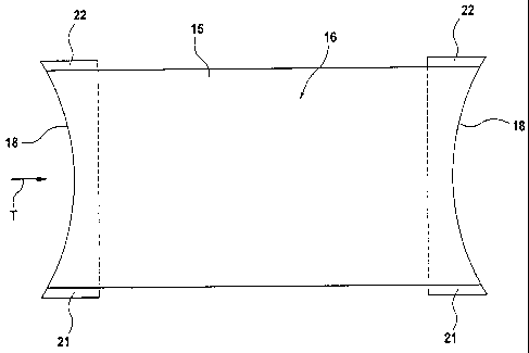
Fig. 2 a top view of the conveying apparatus as in Figure 1 with concave
blade edges, and
Fig. 3a to 3c different embodiments of the design of the deflecting elements
in the
region of the conveying sector.
The shown conveying apparatus serves as a so-called centre belt or guide belt
in a
skinning apparatus for fish. Naturally the conveying apparatus can also be
used
universally in other fields.
The conveying apparatus 10 according to Figure 1 essentially includes an
endless
conveying element 11 which is guided over several deflecting elements 12, a
drive
13 and elements 14 for centering the conveying element 11 for central travel
of the
conveying element 11 on the deflecting elements 12. The conveying element 11
is
formed as a thin and flexible conveyor belt 15, advantageously made of a
flexible
material, e.g. rubber, polyurethane or the like, and has a conveying sector 16
and a
return sector 17. However, the conveyor belt 15 can also be made of other
flexible
materials with or without fabric reinforcement. The conveying sector 16 is the
region
on which the products, in this case fish fillets, are conveyed. The conveying
sector
16 is preferably oriented horizontally and defines the actual conveying plane
E. The
return sector 17 usually runs beneath the conveying plane E.
As already mentioned above, the conveyor belt 15 is guided round several
deflecting elements 12. At least two of the deflecting elements 12, namely the
deflecting elements 12a and 12b, are arranged in the region of the conveying
sector

CA 02614040 2011-09-23
4
16, this being at opposite ends of the conveying sector 16. To be more
precise, the
above-mentioned deflecting elements 12a and 12b are located in the region of
the
input and output of the conveying apparatus 10. The deflecting elements 12a
and
12b in the region of the conveying sector 16 are designed so as to ensure
transfer
of the products conveyed in the direction of transport T without damage. The
deflecting elements 12a, 12b have a shape which is formed or directed inwardly
transversely to the direction of transport T. To put it another way, the
deflecting
elements 12a and 12b in each case drop down from the outside to the inside
along
their length, so that the deflecting elements 12a and 12b have the lowest
point along
the zone between the two outer edges 21, 22. As a result the deflecting
elements
12a and 12b serve as an element 14 for centering. To put it another way, the
elements 14 for centering form an integral part of the deflecting elements 12a
and
12b.
In the shown embodiment the deflecting elements 12a and 12b in the region of
the
conveying sector 16 are designed as blade edges 18. The blade edges 18 are
stationary bodies having a radius in the region of the transition from the
conveying
sector 16 to the 20 return sector 17, and vice versa. In a further embodiment,
not
shown, the deflecting elements 12a and 12b in the region of the conveying
sector 16
can also be other deflecting bodies or deflecting edges. These usually
stationary
deflecting bodies/deflecting edges have a maximum diameter of about 16 to 20
mm
in the edge region 21, 22. The two deflecting elements 12a and 12b, that is,
the
blade edges 18, deflecting bodies or corresponding elements are concave in the
region of the conveying sector 16, such that the curvature is directed
downwards in
a trough shape from the conveying plane E.
Figures 3a to 3c show different embodiments of the deflecting elements 12a and
12b, this involving only shapes by way of example. The deflecting elements
12a,
12b can be designed with a curvature or linear inclined surfaces. Apart from a
symmetrical design (Figures 3a and 3b), asymmetrical shapes (Figure 3c) can
also
be provided. Preferably, however, each deflecting element 12a, 12b has the
lowest
point centrally between the outer edges 21, 22.

CA 02614040 2011-09-23
The deflecting elements 12a and 12b can be made of different materials.
Construction from plastic is preferred. But other, optionally coated or
uncoated
and/or hardened materials can be used as well.
Driving of the conveyor belt 15 can take place by conventional belt drives
with a
single drive roller. In the embodiment described, the drive 13 is a
compression drive.
In the compression drive, driving takes place by two movable rollers 19, 20
which
are synchronised in speed, the conveyor belt 15 being guided between these
rollers
19, 20. At the output of the compression drive, the tension of the conveyor
belt 15 is
therefore almost zero. At least one of the rollers 19 is pushed or pulled
against the
other roller 20 under spring load with a corresponding spring 23, to produce
the
compression connection. Since this is a traditional compression drive, a
detailed
description is dispensed with.
In addition to the deflecting elements 12a and 12b, further deflecting
elements 12
are provided during further travel of the belt, that is, in particular in the
return sector
17. These deflecting elements 12 are preferably arranged in the region of
deflection
points or bends of the conveyor belt 15. In the embodiment shown in Figure 1,
two
additional deflecting elements 12 are provided. The number of deflecting
elements
12 is variable, however. Of the deflecting elements 12 shown, one deflecting
element 12c is movable, this being designed as a deflecting roller. The other
deflecting element 12d is a stationary deflecting rod. The movable deflecting
element 12c has a convex shape. Due to the capacity of the deflecting element
12c
for movement, the spherical shape leads to centering of the conveyor belt 15.
The
stationary deflecting element 12d is, like the deflecting elements 12a and 12b
and
all other possible stationary deflecting elements 12, concave. Like the
deflecting
elements 12a and 12b, all further deflecting elements 12c and 12d can
optionally be
formed from plastic or other materials.

Representative Drawing
A single figure which represents the drawing illustrating the invention.
Administrative Status

2024-08-01:As part of the Next Generation Patents (NGP) transition, the Canadian Patents Database (CPD) now contains a more detailed Event History, which replicates the Event Log of our new back-office solution.

Please note that "Inactive:" events refers to events no longer in use in our new back-office solution.

For a clearer understanding of the status of the application/patent presented on this page, the site Disclaimer , as well as the definitions for Patent , Event History , Maintenance Fee  and Payment History  should be consulted.

Event History

Description Date
Inactive: COVID 19 - Deadline extended 2020-04-28
Common Representative Appointed 2019-10-30
Change of Address or Method of Correspondence Request Received 2018-12-04
Grant by Issuance 2012-05-15
Inactive: Cover page published 2012-05-14
Pre-grant 2012-02-29
Inactive: Final fee received 2012-02-29
Notice of Allowance is Issued 2012-01-11
Letter Sent 2012-01-11
Notice of Allowance is Issued 2012-01-11
Inactive: Approved for allowance (AFA) 2012-01-09
Amendment Received - Voluntary Amendment 2011-09-23
Amendment Received - Voluntary Amendment 2011-07-08
Inactive: S.30(2) Rules - Examiner requisition 2011-01-19
Inactive: Correspondence - MF 2010-08-10
Inactive: IPC removed 2010-02-23
Inactive: First IPC assigned 2010-02-23
Letter Sent 2008-05-22
Request for Examination Received 2008-04-11
Request for Examination Requirements Determined Compliant 2008-04-11
All Requirements for Examination Determined Compliant 2008-04-11
Inactive: Cover page published 2008-03-27
Inactive: Notice - National entry - No RFE 2008-03-25
Letter Sent 2008-03-25
Inactive: Applicant deleted 2008-03-25
Inactive: First IPC assigned 2008-01-26
Application Received - PCT 2008-01-25
National Entry Requirements Determined Compliant 2008-01-03
Application Published (Open to Public Inspection) 2007-01-18

Abandonment History

There is no abandonment history.

Maintenance Fee

The last payment was received on 2012-02-23

Note : If the full payment has not been received on or before the date indicated, a further fee may be required which may be one of the following

  • the reinstatement fee;
  • the late payment fee; or
  • additional fee to reverse deemed expiry.

Please refer to the CIPO Patent Fees web page to see all current fee amounts.

Owners on Record

Note: Records showing the ownership history in alphabetical order.

Current Owners on Record
NORDISCHER MASCHINENBAU RUD. BAADER GMBH + CO. KG
Past Owners on Record
THOMAS GRABAU
Past Owners that do not appear in the "Owners on Record" listing will appear in other documentation within the application.
Documents

To view selected files, please enter reCAPTCHA code :


To view images, click a link in the Document Description column. To download the documents, select one or more checkboxes in the first column and then click the "Download Selected in PDF format (Zip Archive)" or the "Download Selected as Single PDF" button.

List of published and non-published patent-specific documents on the CPD .

If you have any difficulty accessing content, you can call the Client Service Centre at 1-866-997-1936 or send them an e-mail at CIPO Client Service Centre.


Document
Description 
Date
(yyyy-mm-dd) 
Number of pages   Size of Image (KB) 
Abstract 2008-01-03 2 81
Description 2008-01-03 5 227
Representative drawing 2008-01-03 1 5
Drawings 2008-01-03 3 25
Claims 2008-01-03 2 57
Cover Page 2008-03-27 2 40
Description 2011-07-08 6 240
Claims 2011-07-08 2 62
Claims 2011-09-23 2 62
Description 2011-09-23 6 260
Representative drawing 2012-04-24 1 4
Cover Page 2012-04-24 1 37
Maintenance fee payment 2024-04-29 12 467
Reminder of maintenance fee due 2008-03-25 1 113
Notice of National Entry 2008-03-25 1 195
Courtesy - Certificate of registration (related document(s)) 2008-03-25 1 105
Acknowledgement of Request for Examination 2008-05-22 1 190
Commissioner's Notice - Application Found Allowable 2012-01-11 1 163
PCT 2008-01-03 2 69
Fees 2008-04-04 1 44
Fees 2009-04-03 1 104
Fees 2010-04-06 1 49
Correspondence 2010-08-10 1 44
Fees 2011-03-02 1 50
Correspondence 2012-01-11 1 87
Correspondence 2012-02-29 2 58
Fees 2012-02-23 1 54