Language selection

Search

Patent 2614195 Summary

Third-party information liability

Some of the information on this Web page has been provided by external sources. The Government of Canada is not responsible for the accuracy, reliability or currency of the information supplied by external sources. Users wishing to rely upon this information should consult directly with the source of the information. Content provided by external sources is not subject to official languages, privacy and accessibility requirements.

Claims and Abstract availability

Any discrepancies in the text and image of the Claims and Abstract are due to differing posting times. Text of the Claims and Abstract are posted:

  • At the time the application is open to public inspection;
  • At the time of issue of the patent (grant).
(12) Patent: (11) CA 2614195
(54) English Title: CRYOGENIC TANK SYSTEM
(54) French Title: SYSTEME DE RESERVOIR CRYOGENIQUE
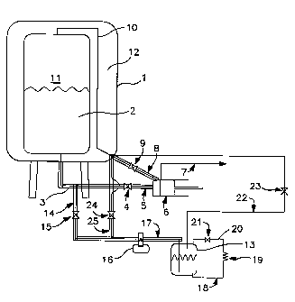
Status: Expired and beyond the Period of Reversal
Bibliographic Data
(51) International Patent Classification (IPC):
  • F17C 13/04 (2006.01)
(72) Inventors :
  • ZIA, JALAL HUNAIN (United States of America)
  • LYNCH, NANCY JEAN (United States of America)
  • ROYAL, JOHN H. (United States of America)
  • GORDON, THURMAN (United States of America)
  • JIBB, RICHARD JOHN (United States of America)
  • MINBIOLE, BARRY ALAN (United States of America)
(73) Owners :
  • PRAXAIR TECHNOLOGY, INC.
(71) Applicants :
  • PRAXAIR TECHNOLOGY, INC. (United States of America)
(74) Agent: MARKS & CLERK
(74) Associate agent:
(45) Issued: 2011-11-22
(86) PCT Filing Date: 2006-06-30
(87) Open to Public Inspection: 2007-01-18
Examination requested: 2008-01-03
Availability of licence: N/A
Dedicated to the Public: N/A
(25) Language of filing: English

Patent Cooperation Treaty (PCT): Yes
(86) PCT Filing Number: PCT/US2006/025552
(87) International Publication Number: WO 2007008453
(85) National Entry: 2008-01-03

(30) Application Priority Data:
Application No. Country/Territory Date
11/174,602 (United States of America) 2005-07-06

Abstracts

English Abstract


A cryogenic tank system wherein cryogenic liquid from a primary cryogenic
liquid storage tank (1) is subcooled by refrigeration generated by a
cryocooler (16), passed into an auxiliary tank (13), pressurized, and returned
to the primary storage tank (1), preferably by way of the cryocooler (16),
thus cooling the storage tank (1) contents and reducing the pressure within
and the vapor losses from the storage tank (1).


French Abstract

L'invention concerne un système de réservoir cryogénique dans lequel un liquide cryogénique provenant d'une cuve de stockage primaire de liquide cryogénique (1) est sous-refroidi par du froid généré par un cryoréfrigérateur (16), est transféré dans une cuve auxiliaire (13), est mis sous pression et est renvoyé dans la cuve de stockage primaire (1), en passant de préférence par le cryoréfrigérateur (16), refroidissant ainsi le contenu de la cuve de stockage (1) et réduisant la pression à l'intérieur de la cuve de stockage (1) et les pertes de vapeur dans cette dernière.

Claims

Note: Claims are shown in the official language in which they were submitted.

-8-
The embodiments of the invention in which an exclusive property or privilege
is claimed are defined as follows:
1. A cryogenic tank apparatus comprising:
(A) a primary tank, a cryocooler, and means for
passing liquid cryogen from the primary tank to the
cryocooler;
(B) an auxiliary tank and means for passing liquid
cryogen from the cryocooler into the auxiliary tank;
(C) means for pressurizing the liquid cryogen passed
into the auxiliary tank, said means for passing
pressurized liquid cryogen into the primary tank
including the cryocooler; and
(D) means for passing the resulting pressurized
liquid cryogen into the primary tank.
2. The apparatus of claim 1 wherein the means for passing
pressurized liquid cryogen into the primary tank
communicates with the lower portion of the primary tank.
3. The apparatus of claim 1 wherein the means for passing
pressurized liquid cryogen into the primary tank
communicates with the upper portion of the primary tank.
4. The apparatus of claim 1 further comprising means for
passing vapor from the auxiliary tank to the primary
tank.
5. The apparatus of claim 1 wherein the means for
pressurizing the liquid cryogen comprises a pressure
building coil.
6. The apparatus of claim 1 wherein the means for
pressurizing the liquid cryogen comprises a liquid pump.

-9-
7. The apparatus of claim 1 wherein the cryocooler is a
pulse tube refrigerator.
8. A method for operating a cryogenic tank system
comprising:
(A) withdrawing liquid cryogen from a primary tank
and subcooling the withdrawn liquid cryogen;
(B) passing the subcooled liquid cryogen into an
auxiliary tank;
(C) pressurizing the subcooled liquid cryogen; and
(D) passing the pressurized liquid cryogen into the
primary tank.
9. The method of claim 8 wherein the subcooled liquid
cryogen is pressurized while in the auxiliary tank.
10. The method of claim 8 wherein the pressurized liquid
cryogen is still subcooled when it is passed into the
primary tank.
11. The method of claim 8 wherein the pressurized liquid
cryogen is passed into the primary tank in the lower
portion of the primary tank.
12. The method of claim 8 wherein the pressurized liquid
cryogen is passed into the primary tank in the upper
portion of the primary tank.
13. The method of claim 8 wherein some of the subcooled
liquid cryogen passed into the auxiliary tank is
vaporized, and the resulting vapor is passed into the
primary tank.

Description

Note: Descriptions are shown in the official language in which they were submitted.


CA 02614195 2008-01-03
WO 2007/008453 PCT/US2006/025552
- 1 -
CRYOGENIC TANK SYSTEM
Technical Field
[0001] This invention relates generally to tank
systems for the containment and the dispensing of
cryogenic liquids.
Background Art
[0002] The storage or other containment of a
cryogenic liquid involves the use of an insulated
vessel or tank to reduce as much as possible the loss
of some of the cryogen due to heat leak into the
vessel. However, even with the use of the best
insulation systems available, a significant portion of
the contained cryogen will vaporize due to heat leak
and will be vented through control, vent or safety
valves. Considering the system operation while
dispensing, liquid cryogen may also be lost due to
vaporization from pump or line heat leak and from pump
priming losses or transfer and filling losses. This
loss of liquid cryogen results in a significant
economic loss.
Summary Of The Invention
[0003] One aspect of the invention is:
[00041 A cryogenic tank apparatus comprising:
(A) a primary tank, a cryocooler, and means
for passing liquid cryogen from the primary tank to the
cryocooler;
(B) an auxiliary tank and means for passing
liquid cryogen from the cryocooler into the auxiliary
tank;

CA 02614195 2008-01-03
WO 2007/008453 PCT/US2006/025552
- 2 -
(C) means for pressurizing the liquid cryogen
passed into the auxiliary tank; and
(D) means for passing the resulting pressurized
liquid cryogen into the primary tank.
[0005] Another aspect of the invention is:
[0006] A method for operating a cryogenic tank
system comprising:
(A) withdrawing liquid cryogen from a
primary tank and subcooling the withdrawn liquid
cryogen;
(B) passing the subcooled liquid cryogen
into an auxiliary tank;
(C) pressurizing the subcooled liquid
cryogen; and
(D) passing the pressurized liquid cryogen
into the primary tank.
[0007] As used herein the term "cryocooler" means a
refrigerator which can produce refrigeration below
240K.
[0008] As used herein the terms "cryogenic liquid"
and "liquid cryogen" mean a fluid which at atmospheric
pressure is a gas at a temperature of 240K.
[0009] As used herein the term "subcooling" means
cooling a liquid to be at a temperature lower than the
saturation temperature of that liquid for the existing
pressure.
[0010] As used herein the terms "upper portion" and
"lower portion" mean these sections of the primary tank
respectively above and below the mid point of the tank.

CA 02614195 2008-01-03
WO 2007/008453 PCT/US2006/025552
- 3 -
Brief Description Of The Drawing
[0011] The sole Figure is a schematic representation
of one preferred embodiment of the cryogenic tank
system of this invention.
Detailed Description
[0012] The invention will be described in detail
with reference to the Drawing. Referring now to the
Figure, insulated vessel or primary tank 1 comprises
storage space 11 and insulated space 12. Storage space
11 contains cryogenic liquid 2, typically at a pressure
generally within the range of from 0 to 600 pounds per
square inch gauge (psig). Among the cryogenic liquids
which can be processed with the use of this invention
one can name hydrogen, helium, neon, oxygen, nitrogen,
argon, carbon dioxide, methane and mixtures such as air
and natural gas.
[0013] Liquid cryogen is withdrawn from primary tank
1 in conduit 3 and passed through valve 4 and conduit
to pump 6. The liquid cryogen is pumped from pump 6
in line 7 to a liquid use point or to a vaporizer for
vaporization prior to being passed to a vapor use
point. Examples of use points include high pressure
cylinder filling, liquid cylinder filling, dewar
filling, gas sampling and analysis, and trailer
transfilling.
[00141 Due to the fact that the pump is generally
warmer than the cryogen, some of the liquid cryogen is
vaporized in the course of being processed through pump
6. This vaporized fluid is passed from pump 6 in line
8 through valve 9 and then in line 10 into the upper
portion of the storage space 11 which contains vapor.

CA 02614195 2008-01-03
WO 2007/008453 PCT/US2006/025552
- 4 -
Preferably, as illustrated in the Figure, vapor return
line 10 passes through insulted space or volume 12 from
the lower portion to the upper portion of tank 1 prior
to communicating with the upper portion of storage
space 11.
[0015] Auxiliary tank 13 is initially at a pressure
less than that of primary tank 1. Some liquid cryogen
is passed from primary tank 1 in line 14 through valve
15 to cryocooler 16 wherein it is subcooled by from 1K
to 100K relative to the pressure in primary tank 1.
[0016] Any suitable cryocooler may be used in the
practice of this invention. Among such cryocoolers one
can name Stirling cryocoolers, Gifford-McMahon
cryocoolers and pulse tube refrigerators. Other
cooling systems, such as a liquid nitrogen heat
exchanger, may also be used. A pulse tube refrigerator
is a closed refrigeration system that oscillates a
working gas in a closed cycle and in so doing transfers
a heat load from a cold section to a hot section. The
frequency and phasing of the oscillations is determined
by the configuration of the system. The driver or
pressure wave generator may be a piston or some other
mechanical compression device, or an acoustic or
thermoacoustic wave generation device, or any other
suitable device for providing a pulse or compression
wave to a working gas. That is, the pressure wave
generator delivers energy to the working gas within the
pulse tube causing pressure and velocity oscillations.
Helium is the preferred working gas; however any
effective working gas may be used in the pulse tube
refrigerator and among such one can name nitrogen,

CA 02614195 2008-01-03
WO 2007/008453 PCT/US2006/025552
- 5 -
oxygen, argon, xenon and neon or mixtures containing
one or more thereof such as air.
[0017] The oscillating working gas is preferably
cooled in an aftercooler and then in a regenerator as
it moves toward the cold end. The geometry and pulsing
configuration of the pulse tube refrigeration system is
such that the oscillating working gas in the cold head
expands for some fraction of the pulsing cycle and heat
is absorbed by the working gas by indirect heat
exchange which provides refrigeration to the liquid
cryogen for the subcooling. Preferably the pulse tube
refrigeration system employs an inertance tube and
reservoir to maintain the gas displacement and pressure
pulses in appropriate phases. The size of the
reservoir is sufficiently large so that essentially
very little pressure oscillation occurs in it during
the oscillating flow.
[0018] The subcooled liquid cryogen is passed from
cryocooler 16 in line 17 into auxiliary tank 13. This
subcooled liquid cryogen is then pressurized to be at a
pressure greater than that of primary tank 1 and
generally to be at a pressure within the range of from
20 to 620 psig. Preferably this pressurization takes
place within auxiliary tank 13. The Figure
illustrates one preferred means for carrying out this
pressurization using a pressure building circuit
wherein subcooled liquid cryogen is passed in line 18
to pressure building coil 19 wherein it is heated and
vaporized. The vaporized cryogen is then passed in
line 20 through valve 21 and back into auxiliary tank
13 wherein the volume expansion resulting from the
vaporization serves to increase the pressure within

CA 02614195 2008-01-03
WO 2007/008453 PCT/US2006/025552
- 6 -
auxiliary tank 13. Another means for increasing the
pressure of the subcooled cryogenic liquid is by use of
a liquid pump, such as a submersible liquid pump
positioned within auxiliary tank 13, or by pump 6 using
a piping and valving arrangement which is not shown.
Other means for increasing the pressure of the
subcooled cryogenic liquid in the auxiliary tank
include introducing compatible vapors into the tank at
appropriate pressures from external sources.
[0019] As the pressure of the subcooled liquid
cryogen increases to be above the pressure within the
primary tank, liquid flow is reversed from auxiliary
tank 13 in line 17 through cryocooler 16 and valve 15
and in lines 14 and 3 into the lower portion of primary
tank 1 which contains liquid. This liquid cryogen flow
reversal serves to keep the contents of primary tank
colder than they would otherwise be, thus keeping the
pressure lower and resulting in lesser vapor loss from
primary tank 1. The liquid flow reversal through the
cryocooler also serves to cool down the liquid further,
thus enhancing the efficiencies of the system.
Optionally the subcooled liquid cryogen may flow from
auxiliary tank 13 to the lower portion of primary tank
1 while bypassing the cryocooler 16. Vapor from
auxiliary tank 13 is passed out from tank 13 in line 22
through valve 23 and then into vapor return line 10 for
passage into the upper portion of primary tank 1. When
the outflow of fluids from auxiliary tank 13 causes the
pressure within the auxiliary tank to fall below that
at the bottom of the primary tank, the cryogenic liquid
flow is again reversed and the cryogenic liquid flows

CA 02614195 2008-01-03
WO 2007/008453 PCT/US2006/025552
- 7 -
from primary tank 1 into auxiliary tank 13 as was
previously described.
[0020] The embodiment of the invention illustrated
in the Figure is a particularly preferred embodiment
wherein pressurized subcooled liquid cryogen may be
passed into the upper portion of the primary tank which
contains vapor. In this mode valve 24 is opened and
some pressurized subcooled liquid cryogen is passed
from auxiliary tank 13 in line 17 through cryocooler
16, and then in line 25 through valve 24 to return line
10. The pressurized subcooled liquid cryogen is then
passed in line 10 to and into the upper portion of
primary tank 1. The introduction of the subcooled
liquid cryogen into the upper portion of the primary
tank serves to condense some of the vapor in this
space. This results in a pressure reduction within the
storage space of the primary tank which further lowers
the potential for vapor loss from the primary tank.
[0021] Although the invention has been described in
detail with reference to a particularly preferred
embodiment, those skilled in the art will understand
that there are other embodiments of the invention
within the spirit and the scope of the claims. For
example, the invention may be practiced with more than
one primary tank and/or more than one auxiliary tank.

Representative Drawing
A single figure which represents the drawing illustrating the invention.
Administrative Status

2024-08-01:As part of the Next Generation Patents (NGP) transition, the Canadian Patents Database (CPD) now contains a more detailed Event History, which replicates the Event Log of our new back-office solution.

Please note that "Inactive:" events refers to events no longer in use in our new back-office solution.

For a clearer understanding of the status of the application/patent presented on this page, the site Disclaimer , as well as the definitions for Patent , Event History , Maintenance Fee  and Payment History  should be consulted.

Event History

Description Date
Time Limit for Reversal Expired 2014-07-02
Letter Sent 2013-07-02
Grant by Issuance 2011-11-22
Inactive: Cover page published 2011-11-21
Inactive: Final fee received 2011-09-02
Pre-grant 2011-09-02
Notice of Allowance is Issued 2011-03-15
Letter Sent 2011-03-15
Notice of Allowance is Issued 2011-03-15
Inactive: Approved for allowance (AFA) 2011-03-03
Amendment Received - Voluntary Amendment 2011-01-19
Inactive: S.30(2) Rules - Examiner requisition 2010-07-19
Amendment Received - Voluntary Amendment 2010-06-07
Inactive: S.30(2) Rules - Examiner requisition 2009-12-07
Inactive: Cover page published 2008-03-27
Letter Sent 2008-03-25
Inactive: Acknowledgment of national entry - RFE 2008-03-25
Inactive: First IPC assigned 2008-01-29
Application Received - PCT 2008-01-28
National Entry Requirements Determined Compliant 2008-01-03
Request for Examination Requirements Determined Compliant 2008-01-03
All Requirements for Examination Determined Compliant 2008-01-03
Application Published (Open to Public Inspection) 2007-01-18

Abandonment History

There is no abandonment history.

Maintenance Fee

The last payment was received on 2011-06-13

Note : If the full payment has not been received on or before the date indicated, a further fee may be required which may be one of the following

  • the reinstatement fee;
  • the late payment fee; or
  • additional fee to reverse deemed expiry.

Please refer to the CIPO Patent Fees web page to see all current fee amounts.

Fee History

Fee Type Anniversary Year Due Date Paid Date
Request for examination - standard 2008-01-03
MF (application, 2nd anniv.) - standard 02 2008-06-30 2008-01-03
Basic national fee - standard 2008-01-03
MF (application, 3rd anniv.) - standard 03 2009-06-30 2009-06-10
MF (application, 4th anniv.) - standard 04 2010-06-30 2010-06-21
MF (application, 5th anniv.) - standard 05 2011-06-30 2011-06-13
Final fee - standard 2011-09-02
MF (patent, 6th anniv.) - standard 2012-07-03 2012-05-30
Owners on Record

Note: Records showing the ownership history in alphabetical order.

Current Owners on Record
PRAXAIR TECHNOLOGY, INC.
Past Owners on Record
BARRY ALAN MINBIOLE
JALAL HUNAIN ZIA
JOHN H. ROYAL
NANCY JEAN LYNCH
RICHARD JOHN JIBB
THURMAN GORDON
Past Owners that do not appear in the "Owners on Record" listing will appear in other documentation within the application.
Documents

To view selected files, please enter reCAPTCHA code :


To view images, click a link in the Document Description column. To download the documents, select one or more checkboxes in the first column and then click the "Download Selected in PDF format (Zip Archive)" or the "Download Selected as Single PDF" button.

List of published and non-published patent-specific documents on the CPD .

If you have any difficulty accessing content, you can call the Client Service Centre at 1-866-997-1936 or send them an e-mail at CIPO Client Service Centre.


Document
Description 
Date
(yyyy-mm-dd) 
Number of pages   Size of Image (KB) 
Description 2008-01-03 7 292
Drawings 2008-01-03 1 11
Representative drawing 2008-01-03 1 10
Claims 2008-01-03 3 73
Abstract 2008-01-03 2 69
Cover Page 2008-03-27 2 40
Claims 2011-01-19 2 63
Representative drawing 2011-10-19 1 8
Cover Page 2011-10-19 1 37
Acknowledgement of Request for Examination 2008-03-25 1 177
Notice of National Entry 2008-03-25 1 204
Commissioner's Notice - Application Found Allowable 2011-03-15 1 163
Maintenance Fee Notice 2013-08-13 1 171
PCT 2008-01-03 9 525
Correspondence 2011-09-02 1 64