Language selection

Search

Patent 2614460 Summary

Third-party information liability

Some of the information on this Web page has been provided by external sources. The Government of Canada is not responsible for the accuracy, reliability or currency of the information supplied by external sources. Users wishing to rely upon this information should consult directly with the source of the information. Content provided by external sources is not subject to official languages, privacy and accessibility requirements.

Claims and Abstract availability

Any discrepancies in the text and image of the Claims and Abstract are due to differing posting times. Text of the Claims and Abstract are posted:

  • At the time the application is open to public inspection;
  • At the time of issue of the patent (grant).
(12) Patent Application: (11) CA 2614460
(54) English Title: TOOL-LESS BLADE CHANGE SHOE FOR A SKINNING MACHINE
(54) French Title: SABOT DE CHANGEMENT DE LAME SANS OUTIL POUR DECOUENNEUSE
Status: Deemed Abandoned and Beyond the Period of Reinstatement - Pending Response to Notice of Disregarded Communication
Bibliographic Data
(51) International Patent Classification (IPC):
  • A22C 17/12 (2006.01)
(72) Inventors :
  • BERGMAN, MATTHEW A. (United States of America)
  • LEBSACK, KENNETH L. (United States of America)
  • MYERS, JAMES L. (United States of America)
  • SAWHILL, MATTHEW P. (United States of America)
  • VELDKAMP, BRENT M. (United States of America)
(73) Owners :
  • STORK TOWNSEND INC.
(71) Applicants :
  • STORK TOWNSEND INC. (United States of America)
(74) Agent: RICHES, MCKENZIE & HERBERT LLP
(74) Associate agent:
(45) Issued:
(86) PCT Filing Date: 2006-07-07
(87) Open to Public Inspection: 2007-01-18
Examination requested: 2008-01-07
Availability of licence: N/A
Dedicated to the Public: N/A
(25) Language of filing: English

Patent Cooperation Treaty (PCT): Yes
(86) PCT Filing Number: PCT/US2006/026646
(87) International Publication Number: US2006026646
(85) National Entry: 2008-01-07

(30) Application Priority Data:
Application No. Country/Territory Date
11/160,756 (United States of America) 2005-07-07

Abstracts

English Abstract


A skinning machine having a skinning blade mounted between a clamp and a shoe.
The shoe has a bore that extends therethrough and a cam arm mounted to a
bottom surface. The clamp has a recess with an aperture disposed therethrough.
A pin extends through the aperture of the clamp and the bore of the shoe and
is retained by the clamp arm.


French Abstract

L'invention concerne une découenneuse pourvue d'une lame de découennage montée entre un élément de serrage et un sabot. Le sabot présente un trou traversant et un levier à came monté sur une surface inférieure. L'élément de serrage présente un évidement à travers lequel est disposée une ouverture. Une tige s'étend à travers l'ouverture de l'élément de serrage et le trou du sabot, cette tige étant retenue par le levier à came.

Claims

Note: Claims are shown in the official language in which they were submitted.

What is claimed is:
1. A skinning machine, comprising: a skinning blade mounted between a
clamp and a shoe, the shoe having at least one bore that extends through the
shoe and at least one cam arm mounted to a bottom surface of the shoe; the
clamp having at least one aperture generally in alignment with the bore of the
shoe; and at least one pin that extends through the aperture and the bore and
is
retained by the cam arm to provide clamping pressure to hold the blade between
the clamp and the shoe.
2. The machine of claim 1 wherein the pin is adjustable.
3. The machine of claim 2 wherein the pin has a first portion and a second
portion threadably received within the first portion.
4. The machine of claim 3 wherein the first portion has a base with a
diameter greater than a diameter of the aperture of the clamp.
5. The machine of claim 3 wherein the second portion has a retaining
head.
6. The machine of claim 3 wherein the second portion has a ridge having a
diameter greater than that of a diameter of the aperture of the clamp.
7. A shoe for use with a skinning machine, comprising: an elongated
member having at least one bore that extends through the member; and at least
one cam arm mounted to a surface of the member.

Description

Note: Descriptions are shown in the official language in which they were submitted.


CA 02614460 2008-01-07
WO 2007/008739 PCT/US2006/026646
TITLE: TOOL-LESS BLADE CHANGE SHOE FOR A
SKINNING MACHINE
BACKGROUND OF THE INVENTION
This invention is directed toward a meat skinning machine and more
particularly a meat skinning machine having a blade holder that does not
require
tools to change the blade and an adjustable pin for clamping a blade between a
shoe and a clamp.
Meat skinning machines are well known in the art and generally have a
tooth roll that pulls meat toward a cutting blade held in place between a
clamp
and a shoe to remove the skin or membrane of the meat. The blade, which is
made of stainless steel, becomes dull over time and must be replaced. To
replace
the blade the skinning machine must be disassembled which requires special
tools to remove the clamp. Disassembly of the machine is cumbersome and time
consuming
Some attempts have been made to solve this problem. For example, U.S.
Patent No. 5,494,478 teaches a machine where the clamp slides backwards and
hooks on a plurality of mushroom-shaped protrusions. This process, however, is
not very hygienic. Another machine, disclosed in U.S. Patent No. 5,211,097
teaches the use of bolts that are fulcrums which hold the blade tightly
between
the clamp and shoe. The top part of the clamp is pushed forward to release the
fulcrum and remove the blade. This, and other machines, however, are not
easily
loosened to allow the clamp to be removed and the machine cleaned. Nor do
these machines maintain the desired clamping pressure when the clamp is
replaced or allow for adjustment as the bolts stretch or wear though use.
Accordingly, there is a need in the art for an improved skinning machine.
Therefore, a primary objective of the present invention is to provide a
skinning machine that is easier to assemble and disassemble.
Another objective of the present invention is to provide a skinning machine
that is easier to clean.
1

CA 02614460 2008-01-07
WO 2007/008739 PCT/US2006/026646
A still further objective of the present invention is to provide a skinning
machine where it is easy to adjust the clamping pressure.
These and other objectives will be apparent to those skilled in the art from
the following claims and written description.
SUMMARY OF THE INVENTION
A skinning machine having a skinning blade mounted between a clamp
and a shoe. The shoe has a bore that extends therethrough and a cam arm
mounted to a bottom surface. The clamp has a recess with an aperture disposed
therethrough. A pin extends through the aperture of the clamp and the bore of
the shoe and is retained by a cam arm. In one embodiment the pin is adjustable
having a first portion that is threadably connected to a second portion.
BRIEF DESCRIPTION OF THE DRAWINGS AND PHOTOS
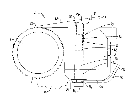
Fig. 1 is a side view of a skinning machine;
Fig. 2 is an exploded perspective view of a portion of a skinning machine;
Fig. 3 is a sectional side view of an adjustable clamping pin; and
Fig. 4 is a bottom plan view of a shoe of a skinning machine.
DETAILED DESCRIPTION OF THE PREFERRED EMBODIMENT
With reference to the Figures, a skinning machine 10 has a frame 12 and
an elongated gripper or tooth roll 14. The tooth roll is rotatably mounted on
the
frame 12. A shoe 16 partially embraces the tooth roll 14. A clamp 18 is
secured
to the shoe 16 with a plurality of adjustable pins 20 to clamp an elongated
cutting
blade 22 between the clamp 18 and the shoe 16 closely adjacent the peripheral
outer surface of the tooth roll 14.
The clamp 18 has a plurality of recesses 24 with each recess having a
centrally located aperture 26. The shoe 16 has a plurality of bores 28 that
extend
through the shoe 16, the bores 28 being in alignment with the apertures 26 of
the
clamp 18. Mounted on a bottom surface 30 of the shoe 16 are a plurality of cam
2

CA 02614460 2008-01-07
WO 2007/008739 PCT/US2006/026646
arms 32 that pivot about a pin 34. The cam arms 32 have a gripping portion 36
at one end and a cam slot 38 at the opposite end.
The adjustable pins 20 extend through aperture 26 of clamp 18 and bore 28
of the shoe and are retained within the cam slot 38 of the cam arm 32 to exert
clamping force upon blade 22. The pins 20 have a first or upper body portion
40
and a second or lower body portion 42. The first portion 40 has a downwardly
extending hollow member 46. The first portion 40 is attached in any
conventional
manner to a base 48. The base 48 has a diameter that is greater than the
diameter of the aperture 26 of the clamp 18. The base 48 preferably is of a
triangular shape such that a top surface 50 of the base lies flush with the
top
surface 52 of the clamp when the pin is installed. The hollow member 46 has a
diameter less than the diameter of aperture 26 and bore 28. The hollow member
46 also has threads 54 on its internal surface. In one embodiment the hollow
member 46 is also engaged by a sea155 that is disposed through the lower body
portion 42.
The second portion 42 preferably has a retaining head 56, a first section
58, a second section 60, and a third section 62. The retaining head 56 extends
out
of the bore 28 of the shoe 16 and has a width greater than the cam slot 38.
The
first section 58 extends outwardly from the retaining head 56 and has a
diameter
that is less than the diameter of the retaining head 56 to form a first
retaining
shoulder 64. The first section 58 has a width less than the width of cam slot
38.
The first section 58 terminates in the second section 60 which has a diameter
greater than the first section 58 to create a second retaining shoulder 66.
The
second section 60 has a squared portion 68 and a cylindrical ridge 70. The
squared portion has a diameter less than the diameter of bore 28 and aperture
26
while the ridge 70 has a diameter less than the bore 28, but greater than the
aperture 26 of the clamp 18.
The second section 60 terminates in a third section 62 that extends
outwardly and has a diameter less than the second section 60. The third
section
62 also has a diameter less than the hollow member 46 and has external threads
72 that threadably mate with internal threads 54 of the hollow member 46. One
3

CA 02614460 2008-01-07
WO 2007/008739 PCT/US2006/026646
skilled in the art will appreciate that the internal and external threads may
be
reversed such that the first portion 40 is received within a hollow section of
the
second portion 42.
In operation, to clamp the blade into place, first portion 40 of pin 20 is
inserted through aperture 26 of clamp 18 and is threadably mated to the second
portion 42 of pin 20 that extends through bore 28 of shoe 16 such that
retaining
head 56 and at least a portion of first section 58 extend beyond the bottom
surface 30 of the shoe 16. The cam arms 32 are then rotated about pins 34 by
applying force to the gripping portion 36 such that the first section 58 is
received
within cam slot 38. The cam arm 32 acting upon the first shoulder 64 of the
retaining head 56 provides the clamping force to hold blade 22 in place
between
the shoe 16 and the clamp 18.
To disassemble the machine 10, the cam arm 32 is rotated in the opposite
direction such that first section 58 is no longer received within cam slot 38.
At
this point the clamp 18 can be removed from the machine 10 for cleaning or
adjustment of the pins. Because both the base 48 and the ridge 70 have a
diameter greater than the diameter of aperture 26, the pins are retained by
the
clamp so they do not fall out and become lost. If the pins 20 are not
adjusted, the
clamp 18 is reassembled and the clamping force is maintained.
To adjust the pins 20 either because of application of use or wear, the first
portion 40 is threadably rotated toward or away from the second portion 42.
The
base 48 and the squared portion 68 provide gripping areas to facilitate
adjustment of the pins.
A skinning machine that is easy to assemble, clean, and adjust the
clamping pressure has been shown and thus all the stated objectives have been
met.
4

Representative Drawing
A single figure which represents the drawing illustrating the invention.
Administrative Status

2024-08-01:As part of the Next Generation Patents (NGP) transition, the Canadian Patents Database (CPD) now contains a more detailed Event History, which replicates the Event Log of our new back-office solution.

Please note that "Inactive:" events refers to events no longer in use in our new back-office solution.

For a clearer understanding of the status of the application/patent presented on this page, the site Disclaimer , as well as the definitions for Patent , Event History , Maintenance Fee  and Payment History  should be consulted.

Event History

Description Date
Application Not Reinstated by Deadline 2010-07-07
Time Limit for Reversal Expired 2010-07-07
Deemed Abandoned - Conditions for Grant Determined Not Compliant 2009-09-04
Deemed Abandoned - Failure to Respond to Maintenance Fee Notice 2009-07-07
Notice of Allowance is Issued 2009-03-04
Letter Sent 2009-03-04
Notice of Allowance is Issued 2009-03-04
Inactive: Approved for allowance (AFA) 2009-02-26
Amendment Received - Voluntary Amendment 2009-01-06
Inactive: S.30(2) Rules - Examiner requisition 2008-09-23
Amendment Received - Voluntary Amendment 2008-07-08
Inactive: Cover page published 2008-03-31
Letter Sent 2008-03-27
Inactive: Acknowledgment of national entry - RFE 2008-03-27
Inactive: First IPC assigned 2008-01-30
Application Received - PCT 2008-01-29
National Entry Requirements Determined Compliant 2008-01-07
Request for Examination Requirements Determined Compliant 2008-01-07
All Requirements for Examination Determined Compliant 2008-01-07
Application Published (Open to Public Inspection) 2007-01-18

Abandonment History

Abandonment Date Reason Reinstatement Date
2009-09-04
2009-07-07

Maintenance Fee

The last payment was received on 2008-06-17

Note : If the full payment has not been received on or before the date indicated, a further fee may be required which may be one of the following

  • the reinstatement fee;
  • the late payment fee; or
  • additional fee to reverse deemed expiry.

Patent fees are adjusted on the 1st of January every year. The amounts above are the current amounts if received by December 31 of the current year.
Please refer to the CIPO Patent Fees web page to see all current fee amounts.

Fee History

Fee Type Anniversary Year Due Date Paid Date
Basic national fee - standard 2008-01-07
Request for examination - standard 2008-01-07
Registration of a document 2008-01-07
MF (application, 2nd anniv.) - standard 02 2008-07-07 2008-06-17
Owners on Record

Note: Records showing the ownership history in alphabetical order.

Current Owners on Record
STORK TOWNSEND INC.
Past Owners on Record
BRENT M. VELDKAMP
JAMES L. MYERS
KENNETH L. LEBSACK
MATTHEW A. BERGMAN
MATTHEW P. SAWHILL
Past Owners that do not appear in the "Owners on Record" listing will appear in other documentation within the application.
Documents

To view selected files, please enter reCAPTCHA code :


To view images, click a link in the Document Description column (Temporarily unavailable). To download the documents, select one or more checkboxes in the first column and then click the "Download Selected in PDF format (Zip Archive)" or the "Download Selected as Single PDF" button.

List of published and non-published patent-specific documents on the CPD .

If you have any difficulty accessing content, you can call the Client Service Centre at 1-866-997-1936 or send them an e-mail at CIPO Client Service Centre.

({010=All Documents, 020=As Filed, 030=As Open to Public Inspection, 040=At Issuance, 050=Examination, 060=Incoming Correspondence, 070=Miscellaneous, 080=Outgoing Correspondence, 090=Payment})


Document
Description 
Date
(yyyy-mm-dd) 
Number of pages   Size of Image (KB) 
Description 2008-01-06 4 219
Abstract 2008-01-06 2 68
Drawings 2008-01-06 4 55
Claims 2008-01-06 1 35
Representative drawing 2008-01-06 1 12
Claims 2009-01-05 1 30
Acknowledgement of Request for Examination 2008-03-26 1 177
Reminder of maintenance fee due 2008-03-26 1 113
Notice of National Entry 2008-03-26 1 204
Courtesy - Certificate of registration (related document(s)) 2008-03-26 1 105
Commissioner's Notice - Application Found Allowable 2009-03-03 1 162
Courtesy - Abandonment Letter (Maintenance Fee) 2009-08-31 1 172
Courtesy - Abandonment Letter (NOA) 2009-11-29 1 164
PCT 2008-01-07 5 196
PCT 2008-01-06 8 264