Note: Descriptions are shown in the official language in which they were submitted.
CA 02614705 2008-01-09
PCT/DE2006/001157 - 1
2005P06469WOUS
Lamp
Technical field
The invention relates to a lamp with at least one light source
and at least one alternative luminous means in accordance with
the precharacterizing clause of patent claim 1.
Prior art
Such a lamp is known, for example, from DE 201 16 719 Ui as a
nightlight lamp. The lamp is in the form of a discharge lamp
with two discharge vessels for producing a main illumination
and an LED for producing an alternative illumination. The main
illumination and the alternative illumination are switched on
alternately via a wall switch and an electrical resistor, which
is connected in parallel with the wall switch, the lamp being
operated in the main illumination mode when the wall switch is
switched on and in the alternative illumination mode when the
wall switch is switched off. In order to prevent the lamp from
switching to the alternative illumination mode given sufficient
brightness when the wall switch is switched off, a photoelement
is provided. One disadvantage of this solution is that it is
not possible to intentionally choose between the main
illumination and the alternative illumination, but that the
lamp automatically changes to the alternative illumination mode
when the wall switch is switched off and in the case of reduced
brightness.
A lamp with a discharge vessel and an LED in which the LED,
i.e. the alternative illumination, can be switched on or off
intentionally is disclosed in WO 02/062106 Al. This lamp
provides control electronics, which are connected to power
supply lines of the discharge vessel and the LED in such a way
CA 02614705 2008-01-09
PCT/DE2006/001157 - 2 -
2005P06469WOUS
that the lamp can be operated in the main illumination mode, in
the alternative illumination mode or in both illumination modes
at the same time as a function of an actuation sequence of a
wall switch. One disadvantage with this solution is that
complex control electronics and a complicated actuation
sequence of the wall switch are required for intentionally
switching on the alternative illumination.
Description of the invention
The invention is based on the object of providing a lamp with
at least one light source and an alternative luminous means,
which lamp makes it possible to manually switch over between
individual operating or illumination modes given minimum
complexity in terms of apparatus.
This object is achieved as regards the lamp by the combination
of features of patent claim 1. Particularly advantageous
embodiments of the invention are described in the dependent
claims.
The lamp according to the invention provides at least one light
source, in particular a low-pressure discharge lamp, for
producing a main illumination and at least one alternative
luminous means, in particular a light-emitting diode
arrangement with at least one LED, for producing an alternative
illumination. The light source and the alternative luminous
means are arranged on a base, in which corresponding
electronics are accommodated. In order to operate the lamp in
the main illumination mode, alternative illumination mode or in
both illumination modes at the same time, a manually actuable
switching arrangement is provided in accordance with the
invention in the base.
CA 02614705 2008-01-09
PCT/DE2006/001157 - 3
2005P06469WOUS
The manually actuable switching arrangement in the lamp base
has the advantage that it is possible to dispense with complex
control electronics and a complicated actuation sequence of a
wall switch as described, for example, in the document
WO 02/062106 Al mentioned at the outset in order to be able to
change between the illumination modes.
In a preferred embodiment, the manually actuable switching
arrangement has a slide, which produces an electrical
connection between an electrical line of the electronics and an
electrical contact element of a power supply line of the light
source or the alternative luminous means. Of course the
electrical connection can also be produced via the slide at the
same time with the two contact elements. Preferably, the
electrical line is fixed on the slide in such a way that it has
a line section extending in the sliding direction for the
purpose of making contact with at least one of the contact
elements.
In order to actuate the slide, it can have two projections,
which extend from its opposite narrow sides through two
recesses, which are preferably arranged diametrically with
respect to one another in the base cover.
In one embodiment, a switching position or a displacement of
the slide is defined by end faces of the slide running onto
inner circumferential sections of the base cover in the region
of the recesses.
The contact element of the power supply line of the light
source and the contact element of the power supply line of the
alternative luminous means can be arranged on an extension of a
dome bearing the LED, which extension extends through the base
cover. Advantageously, the extension has two opposite cutouts
CA 02614705 2008-01-09
PCT/DE2006/001157 - 4
2005P06469WOUS
for passing through the slide, the contact elements each being
arranged in a corner region of the cutouts.
The luminous means preferably has a discharge vessel.
Brief description of the drawings
The invention will be explained in more detail below with
reference to a preferred exemplary embodiment. In the drawings:
Figure 1 shows a schematic side view of a preferred embodiment
of the lamp according to the invention;
Figure 2 shows an exploded illustration of a base cover with a
discharge vessel and an LED and a slide from figure 1;
Figure 3 shows a view from below of the base cover from figure 2,
and
Figure 4 shows a perspective plan view of the slide from
figure 2.
Preferred embodiment of the invention
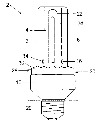
Figure 1 shows a side view of a preferred embodiment of a lamp
2 according to the invention. The lamp 2 is preferably in the
form of a compact fluorescent lamp with a low-pressure
discharge lamp as the light source for producing a main
illumination. The light source has a discharge vessel with
three U-shaped discharge tubes 4, 6, 8, which are arranged on a
base cover 10 of a base 12. The discharge tube 4 is connected
to the discharge tube 6 and the discharge tube 8 via in each
case one connecting web 14, 16, so that a common discharge
space is formed. In order to accommodate the lamp 2 in a
lampholder (not illustrated), a thread section 20 is formed on
the base 12.
CA 02614705 2008-01-09
PCT/DE2006/001157 - 5
2005P06469WOUS
Furthermore, the lamp 2 has an alternative luminous means 22
(indicated by dashed lines), preferably a light-emitting diode
arrangement, for producing an alternative illumination. In the
exemplary embodiment shown, the light-emitting diode
arrangement comprises a light-emitting diode or LED. In order
not to subject the LED 22 to excessively high thermal loading
by means of the main illumination, it is arranged on a dome or
extender 24, which extends from the base cover 10 between the
discharge tubes 4, 6, 8 up to discharge tube regions, the so-
called "cold spots", which are horizontal in the illustration
in the figure, so that the LED 22 is positioned in a region
which is subjected to a low thermal load.
In order to operate the lamp 2 in the main illumination mode,
in the alternative illumination mode or in both illumination
modes at the same time, a manually actuable switching
arrangement is provided in the base 12, of which switching
arrangement two projections 28, 30 of a slide for actuating the
latter are shown in figure 1. The switching arrangement as
shown in the following figures substantially comprises the
slide 32, contact elements 34, 36, which are connected to power
supply lines of the light source 4, 6, 8 and the LED 22, and a
line section 38 of an electrical line 40 of electronics
accommodated in the base 12.
As shown in figures 2 and 3, the base cover 10 has an interior
42, which is delimited by a peripheral circumferential wall 44.
In order to connect the base cover 10 to the base 12, the
circumferential wall 44 has a radially set-back outer
circumferential face 26, so that a set-back body region to be
accommodated in the base 12 and an annular shoulder face 18 for
bearing against a corresponding annular end face of the base 12
are formed. The connection between the base cover 10 and the
base 12 preferably takes place via a snap-action connection,
but adhesive bonding or welding joints are also feasible, for
CA 02614705 2008-01-09
PCT/DE2006/001157 - 6
2005P06469WOUS
example. The slide 32 passes diagonally through the interior
42, two recesses 46, 48, which are arranged diametrically with
respect to one another, for passing through its projections 28,
30 being formed in the circumferential wall 44.
The dome 24 is arranged centrally on the base cover 10 and
extends with an extension 50 into the interior 42. The dome 24
or the extension 50 has a cavity 52, which is delimited by
walls 54, 56, 58, which are arranged substantially in
triangular form with respect to one another. In addition, the
base cover 10 is reinforced by the dome 24 extending into the
interior 42. In order to pass through the slide 32, the walls
54, 56, which are opposite the recesses 46, 48, of the dome 24
each have a cutout 60, 62, in whose corner regions 64, 66 the
contact elements 34, 36 are arranged. In order to better fix
the contact elements 34, 36, they are in the form of hooks,
with them engaging around sections of the corner regions 64,
66.
As shown in figures 2 and 4, the slide 32 has a plate-like,
elongate design, the projections 28, 30 being formed on its
opposite narrow sides. The projections 28, 30 are graduated
symmetrically with respect to the slide longitudinal axis, so
that in each case two end faces 68a, 68b, 70a, 70b are formed
in the transverse direction of the slide on the narrow sides,
which end faces can define a switching position and therefore
an instantaneous illumination mode by means of running onto a
correspondingly opposite inner circumferential section 74a,
74b, 76a, 76b of the circumferential wall 44.
In the slide 32, two drilled holes 78, 80 close to the edge for
accommodating the electrical line 40 are formed in a central
body region 72. In this case, the electrical lines 40 is passed
downward, i.e. from a lower side 84 facing the electronics,
through the first drilled hole 78 and then upward, i.e. from a
CA 02614705 2008-01-09
PCT/DE2006/001157 - -4
2005P06469WOUS
side facing the base cover 10, through the second drilled hole
80. The drilled holes 78, 80 are arranged in the longitudinal
direction of the slide, with a line section 38, from which the
insulation has been stripped and which extends in the sliding
direction, of the electrical line 40 being formed between the
drilled holes 78, 80, which line section 38 can be brought into
contact with at least one of the contact elements 34, 36. In
the process, the line section 38 and the contact elements 34,
36 are arranged one above the other in the longitudinal
direction of the lamp, i.e. in the vertical direction in the
illustration in figure 1, so that the line section 38 and the
respective contact elements 34, 36 touch in a plane which runs
substantially orthogonally with respect to the longitudinal
direction of the lamp. In order to prevent the electrical line
40 from being separated from the slide 32 or the line section
38 from changing its relative position on the slide 32, a
clamping body, 82, for example a sleeve, is provided, which
engages around sections of the electrical line 40 and is fixed
in the region of the first drilled hole 78 on the facing lower
side 84 of the slide 32.
As shown in the illustrations in figures 3 and 4, in the event
of a displacement of the slide 32 to the left, the line section
38 is connected to the left-hand contact element 34, and, in
the event of a displacement to the right, to the right-hand
contact element 36, so that the lamp 2 is operated in the main
illumination mode or in the alternative illumination mode
depending on the assignment of the contact element 34, 36 to
the power supply lines. In a mid-position of the slide 32, the
line section 38 is connected to both contact elements 34, 36,
so that the lamp 2 is operated in the main illumination mode
and in the alternative illumination mode at the same time.
In addition to the switching arrangement described here in
figures 1 to 4 with a slide 32, it is likewise conceivable for
CA 02614705 2008-01-09
PCT/DE2006/001157 - 8
2005P06469WOUS
the switching arrangement to be designed to have, for example,
a manually actuable mechanical or electronic toggle switch or
pushbutton.
It is also conceivable for the dome 24 not to be passed through
the base cover 10 and instead for the base cover 10 to
otherwise be provided with a fixing section for the contact
elements 34, 36 in the region of the extension 50.
The invention discloses a lamp with at least one light source,
in particular a low-pressure discharge lamp, for producing a
main illumination and with at least one alternative luminous
means, in particular a light-emitting diode arrangement with at
least one LED, for producing an alternative illumination, which
are arranged on a base, and with electronics, a manually
actuable switching arrangement for operating the lamp in the
main illumination mode, alternative illumination mode or in
both illumination modes at the same time being provided in the
base.
List of reference symbols
2 Lamp
4 Discharge tube
6 Discharge tube
8 Discharge tube
Base cover
12 Base
14 Connecting web
16 Connecting web
18 Annular shoulder face
Thread section
22 LED
24 Dome
26 Outer circumferential face
CA 02614705 2008-01-09
PCT/DE2006/001157 - 9
2005P06469WOUS
28 Projection
30 Projection
32 Slide
34 Contact element
36 Contact element
38 Line section
40 Electrical line
42 Interior
44 Circumferential wall
46 Recess
48 Recess
50 Extension
52 Cavity
54 Wall
56 Wall
58 Wall
60 Cutout
62 Cutout
64 Corner region
66 Corner region
68a End face
68b End face
70a End face
70b End face
72 Body region
74a Inner circumferential section
74b Inner circumferential section
76a Inner circumferential section
76b Inner circumferential section
78 Drilled hole
80 Drilled hole
82 Clamping body
84 Lower side